
Abstract
Friction stir incremental forming is a dieless forming process achieved through the severe plastic deformation of sheet metals by localized heat through tool friction with sheet metal. Tool rotation contributes significantly to determining the local heat generation and deformation of the sheets. In this study, a novel attempt was made to improve the desired surface quality with minimum tool wear using three different tool coatings. To identify the optimal parameters, process factors such as spindle speed, step size, and table feed were considered with two response parameters forming force and surface roughness. A total of 27 experiments based on a full factorial design were performed. During this optimization using TOPSIS, parameters are selected based on which FSIF parts should attain the minimum forming force and surface roughness. Based on the results obtained, the titanium nitride coating in the tool enhanced the surface roughness and increased the maximum formability. This study provides an optimal parameter setting for AA8011 and an understanding of the friction stir effect during the incremental forming process.
Introduction
Aluminum AA8011 is used in aviation industries, transportation lines, transportation containers, sheet metal works, wires, and rivets. Single-point incremental forming (SPIF) is a promising process for producing a desired complex shape in sheet metals without die expertise.1,2 Nevertheless, it has remarkable processability and is difficult to apply to hard-to-form materials. Therefore, potential modification of the SPIF process is essential to increase the formability. The friction stir incremental forming (FSIF) process is an aggregate of friction stir welding and incremental sheet steel forming.3,4 The FSIF is attained by generating heat (localized temperature) through friction between the tool rotation and workpiece without any external heat applications. The formability of the sheet metal was achieved by attaining the desired shape during dynamic recrystallization. A considerable tool speed increases the temperature in the sheet metal owing to the friction generated between the rotating tool and deformation sheet, which can facilitate the advancement of the formability of sheet metals with poor ductility.
During the FSIF of AA6061, the maximum depth formation and quality of the surface components were influenced by the vertical slope and type of lubricant used when the experiments were performed at the external application temperature. 5 The mechanical characteristics of AA2024 sheets were studied under warm incremental forming. It is identified that the local heating supports the formability and reduces the tool wear. 6 To analyze the behavior of the AA1200 H14 aluminum alloy during the FSIF process, a varied wall-angle conical frustum profile was used to assess formability. To identify the appropriate properties of the Taguchi technique, analysis of variance was employed to identify the optimized sheet thickness as 1.2 mm for low-volume batch production.7–9 The formability of AA 7075, along with its forming forces, was analyzed at different temperatures. An in situ force monitoring system was used to keep track of the forming force, and it was found that increasing the temperature of the sheet metal increases the maximum formability before failure. 10
The thickness distribution and mechanical properties were improved via process optimization. From the literatures, the maximum thinning rate was lower with higher step reductions and larger tools. Furthermore, strain hardening significantly increased the hardness, tensile strength, and yield strength of the sheet segregated from the initial sheet, 11 and was used to develop a low-weight ultrathin fin on an A5083 aluminum plate. As a result, the low profile of 0.5 mm and less than fins with 0.5 mm is produced with a 3 mm thick A5083 aluminum plate. Thicker fins were found to influence the deformable material, 12 and the influence of the AA7075 process parameters was verified using pyramid frustum and a truncated funnel. Mechanical properties, such as tensile strength, surface quality, and microhardness, were tested. It is observed from the study that increases in the tool rotational speed maximize material formability through local heat and plastic deformation. 13 The thickness distribution of aluminum AA6061-T6 thin sheets was studied. The forming force generated was analyzed with respect to tool diameter and sheet thickness. It was found that an increase in the tool diameter increased the excess heat generation, and a reduction in the tool diameter resulted in tool wear and high forming force generation. The optimized tool diameter is essential for the appropriate thin sheet to attain maximum formability. 14 The optimization of process parameters was performed for AA5052-H34 thin sheets and observed the formability raised due to the heat effect and the dynamic recrystallization occurs when the tool rotational speed is higher than 7000 rpm. 15
Li et al. 16 investigated microstructure formed on combined FSIF with synchronous bonding method and mechanical properties are increased by synergetic process. Zhan et al.17,18 investigated a two stage novel FSIF process to obtain the uniform microstructure on the aluminum alloys. Devanathan and Babu19,20 done a research to improve the machining parameters in friction stir welding process by applied the coating on tool.
The friction between the tool and the sheet metal limits the surface quality of the SPIF process by peeling off the microchips from the sheet layer. This reduced sheet thickness, which tended to fail faster than was predicted. The forming force increased significantly due to the formation of microchips on the surface of workpiece. Furthermore, the sheet metal surface quality also reduced. To overcome this issue, tool coating technique is chosen as solution. The effect of coating to improve the formability and surface quality is discussed in detail in this study. In addition, TOPSIS was used to rank the influencing the input parameters. Meanwhile, ANOVA was to determine the ideal parameter combination for tool coating, step size, spindle speed, and table feed to obtain the optimum results.
Materials and methods
Materials
The effects of different tools and formability parameters are investigated in this study. The subsequent sections discuss material properties, tooling, parameter optimization, confirmation experiments, and numerical simulations. AA8011-H19 was selected as the candidate for the present work because it is effectively employed in heat exchangers, fuel lines, and liquefied natural gas tankers owing to its high strength and corrosion resistance. 21 The chemical composition of AA8011-H19 are presented in Table 1. The incremental formation of AA8011 sheets can facilitate the manufacturing of high-strength components. Grid circle printing was performed to measure the strain levels of the aluminum alloy sheets.
Chemical composition.

In the FSIF process, the frictional warmness caused by the tool rotation at the interface with the workpiece causes an increase in the surface temperature and improves the formability of the sheet metal. FSIF was used to form hard-to-form steel sheets without an external heat source. Excessive friction between the device and the steel sheet can result in poor floor quality on deformed surfaces. 22 To overcome the excessive heat generation, different tool coatings, such as tools without coating (WC), polytetrafluoroethylene (PTFE) coating, and titanium nitride (TiN) coating, are employed, as shown in Figure 1(b) to (d). Physical vapor deposition (PVD) technique was employed both PTFE and TiN coating. Tool was coated between 3 and 5 μm range. This tool study empowered the process with less tool wear and an improved surface finish.

(a) FSIF tool 2D sketch. (b) FSIF tool without coating. (c) FSIF tool with PTFE coating. (d) FSIF tool with TiN coating.
Experimental method
Friction stir incremental forming is a combination of friction stir welding and incremental sheet-metal forming. A non-consumable tool was used in the friction stir welding (FSW) process to unite two facing workpieces without melting the material. As a result of the heat created by the friction between the rotating tool and the workpiece material, a softened area develops close to the FSW tool. FSIF is not friction heating but friction stirring because in this process, as the tool rotation rate increases, formability increases when the tool rotation rate exceeds the maximum value by dynamic recrystallization. In friction stir incremental forming, the frictional heat generated by high tool rotation on the interface between the tool and the workpiece causes an increase in the local temperature of the sheet and enhances the formability of the material. The FSIF is used to form hard-to-work metal sheets without heating by an external heat source such as an electric furnace or electric heater. However, excessive friction between the tool and the sheet metal may result in deformed pieces with poor surface quality.
In this study, FSIF was conducted using a vertical milling machine (VMC 850). To produce these shapes, a hardened hemispherical tool manufactured from HSS with a diameter of 10 mm was employed. To measure the forming force dynamometer setup (Kistler 9129AA type dynamometer) was attached with equipment. TR210 mobile surface roughness meter (resolution = 0.01 µm, driving length = 6 mm, sensor angle = 90°) was employed to measure the roughness. The specimen size of the AA8011 alloy sheets was 300 × 300 × 1.2 mm. The factors considered for the FSIF processing of the cone shape and triangular pyramid shape on AA8011 sheets include the tool type, step size, spindle speed, and table feed. The design and development of the fixture were performed using VMC 850. The influencing process parameters, such as the tool type, step size, spindle speed, and table feed, were studied using design of experiments (DOE) and selected for optimization using TOPSIS to attain appreciable surface roughness. A mathematical model defining the importance of the process parameters was defined. A numerical simulation was performed using the ABAQUS software to calculate the stress, reaction force, displacement, and strain levels of the formed components. Trials are planned to assess the shape accuracy of the component made using SPIF as well as the fracture strains of AA8011.
Design of experiments
The major factors that induce the FSIF process include tool type, step size, spindle speed, and table feed. TOPSIS method was deliberated for the study of optimizing the response parameters such as forming force and surface roughness. TOPSIS is a multi-criteria decision-making approach, as shown in Figure 2, that discovers the optimum option from a group of alternatives by minimizing the distance between the ideal and least desirable solutions and maximizing the distance between them.23,24

Decision-making model of the SPIF process.
TOPSIS logic was used to define the positive and negative ideal solutions. The positive ideal solution maximizes the performance while minimizing constraints, whereas the negative ideal solution maximizes the constraints while minimizing the performance. The optimal alternative is the one that is most similar to the positive ideal solution while being the most dissimilar to the negative ideal solution. TOPSIS ranks options according to their “relative resemblance to the ideal solution,” avoiding situations when both positive and negative ideal solutions have the same similarity.
In the response analysis, two parameters were considered: the forming force and surface roughness. There are L27 orthogonal array was selected and there are a total of 27 experiments to be conducted containing three levels four factors in a matrix format as shown in Table 2. 25
Parameters and its levels for forming process.

TOPSIS aims to determine the most reliable solution for the current situation. This method includes attribute selection for attaining the best solution and analysis under all exciting conditions. This method provided the most comprehensive solution. The key benefit of the TOPSIS system is its ability to perform in today’s working environment as well as its ease of computation. The following steps must be considered:
(a) TOPSIS is the best standing tool because it has to choose other possibilities that exclude the elements of all parameters, resulting in a normalized score. The normalized output matrix (rij) obtained using the following equation is presented in Table 3.

L27 orthogonal array and output response values.

xij is the regularized significance of the term “i” investigational run related to the output reaction term “j.”
(b) The creation of the normalized significance and the weighted ideals yielded the subjective normalized matrix (
(c) Each reaction was identified as a perfect substitute for both the greatest substitute act (S+) and poorest substitute act (S−).
If suppose the criteria “j” consumes a suitable act, then

(d) The greatest substitute value (D+ ij ) from S+ act and the poorest substitute value (Dij) from S-act were used to assess the accuracy of the criteria. The selected values of D+ ij and Dij were calculated using the following equations:


Where i = 1, 2, 3, …, 27.
(e) Values of the closeness coefficient (Ci) for each substitution were calculated using the following equation:
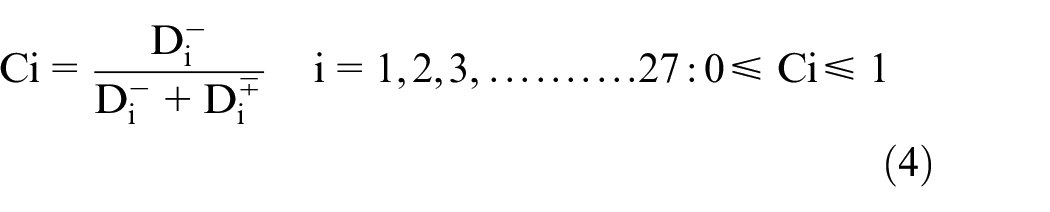
The finest possibility is selected based on the preference rating, which is similar to the optimal solution when ordered by the Ci value.
The optimal degree of the shaping parameters for using the TOPSIS method was determined. Various combinations of process parameters and output response values, such as the forming force and surface roughness values, are mentioned using the L27 orthogonal array in Table 3.
Results and discussion
FSIF experiments were performed using different tool coatings. FEM simulations were performed to analyze the stress. 26
Table 4, gives the result of the positive and negative ideal solutions for the 27 experiments. The values of the forming forces and surface roughness are listed in Table 4.
Positive and negative ideal solution for aluminum alloy.

The best option was chosen based on the preference rank, which was extremely close to the ideal answer when sorted by Ci value, as shown in Table 5. 27
The values of the Closeness coefficient and their position.

In experiment no. 21, the best optimal process parameters were found in SPIF at a TiNC tool type, step size of 0.5 mm, spindle shaft speed of 800 rpm, feed of 1400, and parallel closeness coefficient value of 1.000, is shown in Figure 3.

Closeness coefficient of each test.
Table 6 indicates the mean closeness coefficient for each step of the forming limits for SPIF Forming. Each level of the process factor exhibited the best forming process parameters. 28 The optimal level of the forming parameter combinations was expressed by the maximum mean closeness coefficient of each process factor, as shown in Figure 4. The standoff distance is perhaps the most significant factor, with a large small value that is greater than that of the other forming parameters. Because the forming tool rapidly penetrates the workpiece at a high feed rate, the forming quality increases at the maximum feed rate based on optimal process parameters.
Mean response for closeness coefficient values (AA8011).

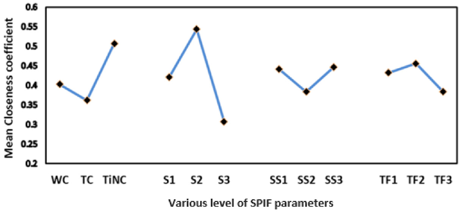
Mean closeness coefficient values of SPIF parameters.
Mathematical model
RSM is a statistical forming method for influencing the association among several process factors and reactions and preferred standards, and for defining the importance of these process parameters. 24
WC = −2.37467 + 3.62641* Step size + 0.431235* Sheet thickness + 0.001311* Spindle speed-0.001112* Step size* Spindle speed-0.000458* Sheet thickness* Spindle speed-1.94865* Step size 2 + 0.309699* Sheet thickness 2 .
PTFE = −2.03335 + 3.97583* Step size + 0.242521* Sheet thickness + 0.001174* Spindle speed-0.001112* Step size* Spindle speed-0.000458* Sheet thickness* Spindle speed-1.94865* Step size 2 + 0.309699* Sheet thickness 2 .
TiN = −2.37539 + 3.54311* Step size + 0.472988* Sheet thickness + 0.001353* Spindle speed-0.001112* Step size* Spindle speed-0.000458* Sheet thickness* Spindle speed-1.94865* Step size 2 + 0.309699* Sheet thickness 2 .
An analysis of variance (ANOVA) test was performed at a confidence level of 95%, and the results are reported in Table 7. It was carried out to determine the influencing level of each input process parameter that influences the SPIF Forming’s multi-response features 29 the SPIF’s subdivisions of the ANOVA test considered the forming input and interaction parameters. According to the results of the ANOVA test, sheet thickness had the highest contribution of 34%. 30 The model validation was performed using normal plots. The graphs based on the central limit theorem are known as normal probability plots, and Figure 5 shows typical plots of the responses. Furthermore, the residuals lack structure and contain no discernible pattern. Thus, the model was determined to be adequate. Furthermore, as shown in Figure 6, the residual versus predicted plots are normally distributed, and there appears to be no violation of variance equality. The inclined line (Figure 7) is close to the actual versus projected values, indicating good significance.
Results of ANOVA for SPIF process.

SS: sum of square; DOF: degree of freedom; MSS: mean square × significant factor.

Normal probability plot of residuals.

Residual versus predicted plot.

Actual versus predicted plot.
Based on the plot, three-dimensional surface plots for tools without coating (WC tool), polytetrafluoroethylene coating (PTFE tool), and titanium nitride coating (TiN tool) with respect to the TOPSIS grade are displayed in Figure 8(a) to (c).
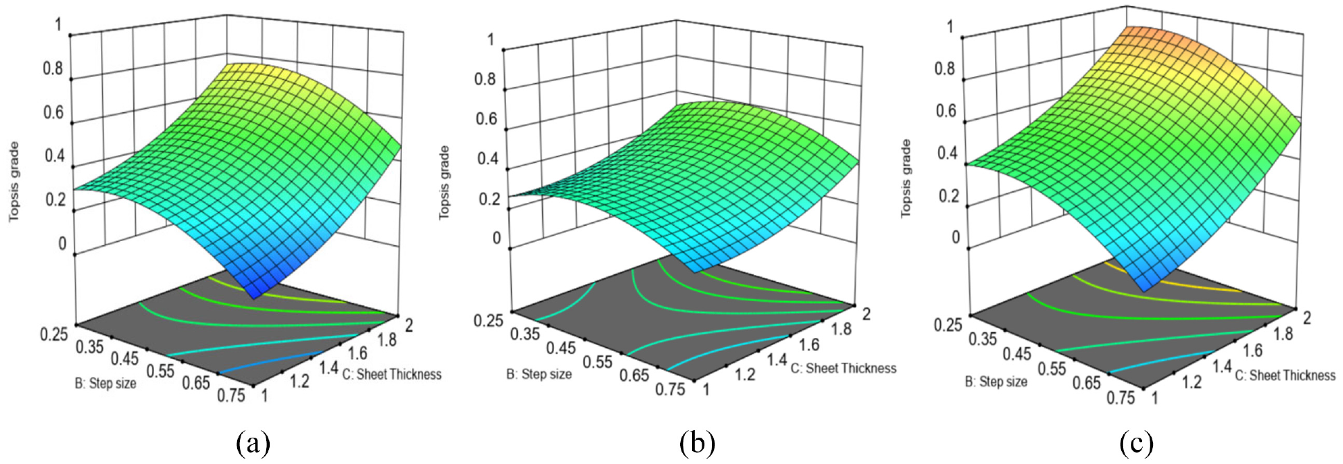
(a) 3D plot for WC tool. (b) 3D plot for PTFE tool. (c) 3D plot for TiN tool.
Results of the optimal forming parameters
Table 8 presents the optimal forming parameters for the TOPSIS method. The best output response parameters achieved by SPIF at a tool type of TiNC, step size of 0.5 mm, spindle speed of 800 rpm, and table feed of 1400 are forming force of 702 N and surface roughness of 0.361 m. Because the improved forming process parameter settings in Table 8 are similar to the optimal conditions, no confirmation test was performed. The components formed by the FSI using the three coated tools are shown in Figure 9. The difference and smoothness can also be observed in Figure 9, and the fish-scale formation during the FSIF in both profiles is displayed in Figure 10. The fish-scale-like formation was due to the plastic deformation of the material as a result of heat generation caused by the speed of tool rotation.
Comparison of optimal Forming parameters and experiments.


(a) FSIF experiments cone (WC). (b) FSIF experiments pyramid (WC). (c) FSIF experiments cone (PTFE). (d) FSIF experiments pyramid (PTFE). (e) FSIF experiments cone (TiN). (f) FSIF experiments pyramid (TiN).

(a) Fish scale track formation under the SPIF process (cone). (b) Fish scale track formation under the SPIF process (pyramid).
Measurement of major and minor strain
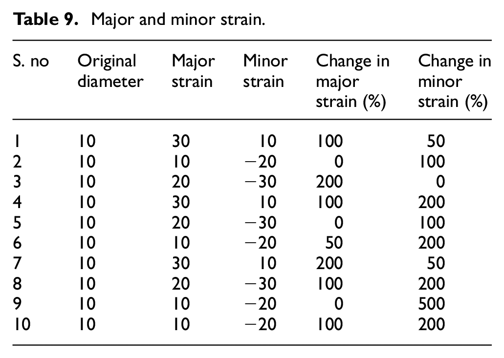
The preliminary sheet was marked using uniform circular grids with a diameter of 10 mm. After the metallic sheet was fashioned, the marked circles were deformed into ellipses of various sizes. The duration of the main axis of the ellipse corresponds to the main stress and the duration of the minor axis corresponds to the minor stress, as shown in Figure 11. The durations of the main and minor axes were measured using digital calipers, as shown in Table 9. Both traces were calculated using the following formula:

Forming limit diagram.
Major and minor strain.
Numerical modeling of the spif process
The formability and forming force of aluminum sheets in incremental sheet forming were examined at various temperatures. ABAQUS software was used to analyze the forming parameters. The deformation levels of cone and triangular pyramid shapes were investigated using ABAQUS FEM analysis in our experimental work. The effects of the forming forces on the formed sheets are required for this investigation.
Figures 12(a) and 13(a) shows the contours of the von Mises stresses and strains acting on the cone shape and forming. The simulations revealed that the stress level increased as the depth of the portion increased. During deformation, the highest stresses arise in the contact zone between the forming tool and sheet. The load level was applied at maximum 708.2 N ranges in the FEM model, and the sheet was able to sustain the formation of a cone shape. Figures 12(b) and 13(b) shows the contours of the von Mises stresses and strains acting on the triangular pyramid shape forming. 31 To maximize formability, step-over values should be as small as possible. Nevertheless, selecting very small step-over values increases the processing time, which has an impact on productivity. As a result, the ideal compromise between step-over and process time was carefully considered.

(a) Stress analysis (cone shape). (b) Stress analysis (pyramid shape).

(a) Reaction force analysis (cone shape). (b) Reaction force analysis (pyramid shape).
The displacement and stress acting on the cone-shaped and triangular pyramid-shaped sheets were analyzed using FEM analysis. Figure 14(a) and (b) shows a comparison of the displacement levels of the two formed sheets. It was stated that the stresses acting on the cone and triangular pyramid shapes influence the forming force parameter. Figure 15 shows a comparison of the strain energy and time attained in the sheet. At the series level, the forming time and energy of the sheet vary at several time intervals. 32 Using a plane-strain deformation model and forming-limit diagram, the strain distributions and forming loads of the shell were proposed and tested. Second, an FEM based on shell theory is used to calculate the bulging height, strain, and stress distributions and to explain plane-strain deformation in incremental forming, which is a rare event. The shell of the cone of the triangular pyramid predicted by the approximate deformation and FEM analyses was reasonably close to the experimental values for the annealed aluminum sheet.
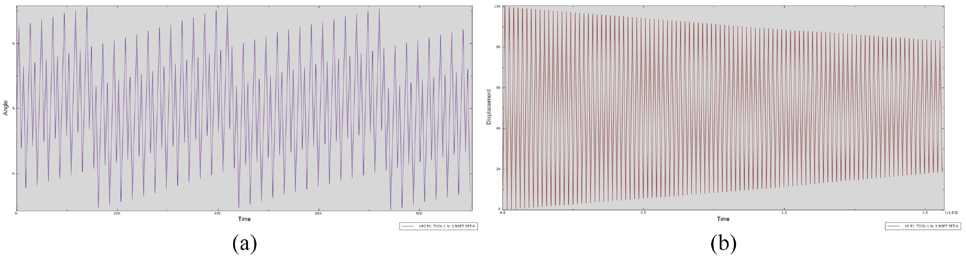
(a) Displacement analysis (cone shape). (b) Displacement analysis (pyramid shape).

Strain level analysis comparison (cone and pyramid shape).
Conclusions
The FSIF process of AA8011 sheet metal was performed, and the FSIF was optimized using TOPSIS to identify the optimized parameters. FEM analyses were performed to predict the stress induced during the process and formability. The results are as follows.
Tool coating had a positive influence on the forming height and surface quality. The TiN-coated tool produced increased formability compared to the other two tool materials and minimized surface roughness.
It was found that the Forming force of 702 N and surface roughness of 0.361 µm is the best output response parameters, which are produced by friction stir incremental forming process at a Step size of 0.5 mm, Spindle speed of 800 rpm, and Table feed of 1400 mm/min.
It was found that a smaller step size results in improved formability and higher localized deformation.
FEM analysis was conducted to analyze the various stresses acting on the sheets during the forming process. A comparison between the force and time was performed to study the impact of the process parameters.
Footnotes
Handling Editor: Chenhui Liang
Declaration of conflicting interests
The author(s) declared no potential conflicts of interest with respect to the research, authorship, and/or publication of this article.
Funding
The author(s) received no financial support for the research, authorship, and/or publication of this article.
Data availability
The data used to support the findings of this study have been included in this article.