
Abstract
In this paper, based on the development of the non-pyrotechnic low impact connection and separation device for heavy load connection of large space vehicles, the design method of connection and separation device is studied. The traditional heavy load connection separation device has a strong loading capacity, but the release of system energy will cause a huge impact during separation. This paper considers the transfer of impact energy in the mechanism design process, reduces separation impact based on energy flow analysis. Based on the analysis of the DOF (Degree of Freedom) constraint function of the separation system and the working requirements of the separation mechanism, the movability model of separation system was established. According to the research on DOF constraints and release, the key of force constraints in DOF constraints of the separation mechanism is obtained, and the separation mechanism that can implement the force constraints and release is analyzed. Furthermore, based on the energy flow analysis of the separation mechanism, the design method of the low impact separation mechanism is proposed, obtained a non-self-locking thread pair connection separation mechanism. The effectiveness of the design method was verified by the energy conversion analysis of the separation mechanism.
Introduction
The space connection separation mechanism is the core component of the spacecraft system to achieve locking, releasing and separating functions during the launch and orbit state. It is widely used in rocket stage separation, satellite and arrow separation, solar wing deployment, payload release, in-orbit docking, and maintenance, etc. Its function and performance directly affect the success or failure of spacecraft launch and in-orbit work. The traditional connection and separation mechanism realizes the connection through the structural loading capacity, and uses the pyrotechnic operation to implement the structural failure and separation after entering orbit. This disposable technology has many problems, such as high separation impact, explosive pollution and non-reusable, which severely limits its application in various new spacecraft, payloads and space missions. With the development of manned spaceflight, earth observation, deep space exploration and on-orbit operation, the demand for on-orbit non-pyrotechnical low impact separation for high-precision payloads, optical systems, micro-nano satellites, and other structures is becoming more and more urgent.
Based on the principle of reducing the impact of non-pyrotechnic devices, Yue 1 classified the existing research from the perspective of driving technology and system design method, and summarized the common mechanism types of non-pyrotechnic low impact connection separation devices according to the design concept of vibration reduction in the system design method. Li 2 introduced the materials, structures and working principles of shape memory polymers and their composites in the aerospace field. Hwang 3 presented a compact non-explosive actuator device activated by a thermal cutting method using nickel chrome wire, which has the characteristics of low impact and lightweight. Ding 4 proposed a compact non-explosive actuator device activated by a thermal cutting method using nickel chrome wire, which has the characteristics of low impact and lightweight. To improve the reliability of the small satellite separation device, Choi5,6 proposed a design, manufacturing and testing method of a wire cutting-based non-pyrotechnical drive device model for small satellites, developed a non-pyrotechnic separation device activated by the thermal cutting method of nickel-chromium wire, and analyzed the reliability of the developed separation device by fault tree analysis. Zhang 7 developed a design method of load transfer SMA (Shape Memory Alloys) actuator for separation device. Tomizuka8,9 proposed a design scheme of segmented nut release driven by shape memory alloy wire, and verified the good response performance and high reliability of the device through experiments. Wei 10 proposed an intelligent release device without fireworks, light weight and simple structure made of shape memory polymer composite material, and a tensile test was conducted to obtain the structural strength and release time of the device. Chen 11 analyzed the vibration characteristics and energy transfer of the box composite structure. Zhang 12 applied the dynamic stiffness method to study the free vibration and forced vibration characteristics of three-dimensional coupled thin plate structure considering bending vibration and in-plane vibration. Based on the dynamic sensitivity technique, Yimin 13 proposed a sensitivity analysis method for path parameters of the vibration transfer path system. Navazi 14 proposed a new method to measure the energy density of plate high frequency vibration, and used the proposed method combined with the accelerometer to measure the kinetic energy and potential energy density. Song 15 used energy flow analysis to study the transfer of vibration energy through beam-plate connections. Garcia16,17 proposed an impact load analysis method using a finite element model under the comprehensive consideration of the uncertainty of mathematical treatment and load characteristics, and carried out a numerical analysis on the beam structure with this method, which verified the effectiveness of the proposed method. Wang18,19 proposed a design method for a reusable modular locking release device, and applied the principle of mechanical stability of plant root growth to the layout optimization of a satellite bottom locking device. Xiong 20 used finite element simulation and experiment to analyze the impact mechanism and characteristics in the process of unlocking the separation nut. It is concluded that adjusting the preload without changing the loading and structure of the separation device has no obvious impact on reducing the impact, but the impact of the separation device can be reduced by reducing the impact of the inner sleeve. Zhao 21 established a finite element model of pyrotechnical separation nut and simulated the whole separation process to study the effect of prestress on the separation shock wave and its two shock sources. Cui 22 presented a modeling and simulation method for the comprehensive prediction of satellite separation dynamic characteristics considering interface ring flexibility.
At present, a series of progress has been made in the design and application of non-pyrotechnic connection separation devices. Compared with traditional pyrotechnic devices, there are obvious improvements in reducing shock release levels, improving safety and reducing pollution, but there is a lack of systematic design methods for heavy load low impact connection separation devices. The research objects based on energy flow analysis are mostly limited to relatively simple components such as plates and rods. This paper considered the transfer of impact energy in the process of mechanism design, based on energy flow analysis to reduce the design requirements of separation impact combined with heavy load connection, and carried out an innovative design of separation mechanism.
Movability model and analysis of separation system
Kinematic modeling and movability analysis
The connection separation system is composed of the connected piece, the connection separation device and the foundation body. The connection separation device is responsible for the DOF constrained work between the connected piece and the foundation body. This section starts with the essence of the kinematics of the separation mechanism and analyzes the DOF of the connection and separation of the separation mechanism. The functions and characteristics of force constraint, shape constraint and force-shape combination constraint modes were analyzed according to the stiffness requirements of the separation mechanism in the connection state. The key constraints of the connection and separation states were obtained by constraint analysis, and the criterion of immobility in the connected state and movability in the separated state was derived. As the core mechanism for imposing and releasing force constraints, the separation mechanism can be divided into structural failure and structural non-failure according to whether a structural failure occurs during the separation process. According to low impact constraints, appropriate separation mechanism types should be selected as the focus of subsequent analysis, the analysis ideas are shown in Figure 1.
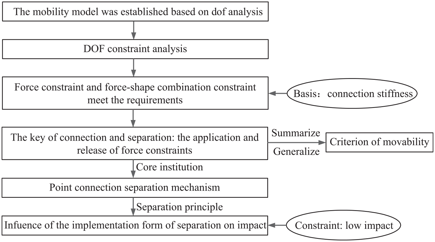
The kinematic analysis ideas of the connection separation system.
The working process of the separation mechanism in the actual connection separation task is as follows: Firstly, the connecting part and the foundation body are transformed from a separate state to connected state, and then the connected piece and the foundation body are transformed from the connected state to separate state. The separation state was defined as a movable state and the connection state as an unmovable state. The functional characteristics of the separation mechanism were studied by analyzing the movability of the separation system.
In the separation state, the kinematic pair may exist between the connected piece and the foundation body, which can be discussed in two cases: (1) If there is a kinematic pair between the connected piece and the foundation body, generally there is only one kinematic pair, then the movable DOF of the connected piece is equal to the DOF of the kinematic pair; (2) If there is no kinematic pair between the connected piece and the foundation body, the movable freedom of the connected piece is 6. In the connected state, the connection between the connected piece and the foundation body is completely constrained, and the DOF of the connected piece is 0.
From separated state to connected state is the process of applying DOF constraints, and from the connected state to separated state is the process of releasing DOF constraints. This section studies the characteristics of DOF constraints and release from the perspective of applying freedom constraints from separating movable states to connecting immovable states, and establishes the movability model of the connected separation system, as shown in Figure 2.

Schematic diagram of the movability model of connection and separation system (Cpt is the kinematic pair constraint between the connected piece and the foundation body, CF is the force constraint provided by the separation mechanism, Cct is the shape constraint generated by the contact of the separation surface, FP is the preload of the connected separation mechanism, and FN is the reaction force of FP).
The DOF constraint includes force constraint and shape constraint. In the separated state, the joint constraint Cpt (0 ≤ Cpt ≤ 5) between the connected piece and the foundation body is a shape constraint, and the DOF of the connected piece are:

In the connected state, the separation mechanism can provide CF, and the contact of the separation surface can generate Cct, which together with the kinematic pair shape constraint Cpt constitute a system DOF constraint C = 6, and the system DOF are:

Movability criterion based on DOF constraint analysis
The DOF constraint is the core of the separation mechanism to realize the connection function. How to realize the DOF constraint is an important research content in the design of the separation mechanism. The DOF can be divided into translational DOF and rotational DOF. The two DOF can be constrained in the same way. Therefore, by analyzing the constraint mode of one DOF, the constraint law of two DOF can be obtained, and then the constraint law of six DOF in space can be obtained.
Taking the foundation body and the connected piece form a translation pair with one DOF in the separated state as an example, only the constraints of the translation DOF in the x-direction of the connected pieces are analyzed, and the shape constraints of the existing translation pairs in the directions of other DOF are not within the scope of research, as shown in Figure 3.
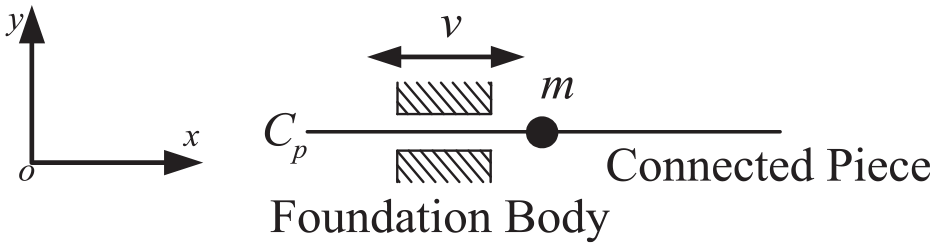
Schematic diagram of the separation state of the translation pair.
The shape constraint Cpt of the translation pair includes
According to the different types of DOF constraints, three methods of force constraint, shape constraint and force-shape constraint can theoretically be selected, as shown in Figure 4. Force constraint is the constraint reaction force that prevents the movement of the connected piece from being applied in the direction of the DOF of the connected piece. The most representative force is static friction force Ff, as shown in Figure 4(a). The force constraint can adjust the size of the constraint force according to the size of the external force to achieve the DOF constraint effect. The shape constraint imposes positioning limit constraints on the positive and negative directions of the DOF of the connected piece, which can achieve the effect of DOF constraint, as shown in Figure 4(b). Force-shape combination constraint imposes both shape constraint and force constraint on the positive and negative directions of the DOF of the connected piece, which can also achieve the DOF constraint effect, as shown in Figure 4(c).

Schematic diagram of three constraint modes of the connection state of translation pair: (a) force constraint; (b) shape constraint; (c) force-shape combination constraint.
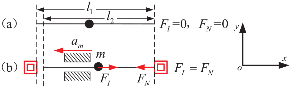
In the force constraint mode, if the connection separation system is not subjected to external forces, the constraining force Ff = 0. In the process of launching into orbit with the vehicle from the ground, the connected separation system needs to bear a severe vibration load. In the vibration environment, assuming that the maximum acceleration direction of the connected separation system is x negative, and the magnitude is am, then the inertia force subjected to the connected piece m is FI, and the force constraint will provide a friction force Ff in the opposite direction, as shown in Figure 5.

Schematic diagram of overload deformation in force constraint mode: (a) force constrain in state FI≤ Ffm and (b) force constrain in state FI > Ffm .
Assuming that the maximum static friction force of the connected piece is Ffm, when FI ≤ Ffm, CF can complete the DOF constraint function of the connected piece. When FI > Ffm, the connected piece is in a force imbalance state and moves in the direction of the DOF. The force constraint CF fails, and the connection function cannot be completed.
In the shape constraint mode, if the connected separation system is not subjected to external force, there is no interaction force between the shape constraint and the connected piece, and the length of the connected piece in the direction of freedom is l1, as shown in Figure 6(a). In the vibration environment, it is assumed that the maximum acceleration direction of the connected separation system is x negative, and the magnitude is am. Then, the inertia force subjected to the connected piece m is FI, and the shape constraint will provide a support reaction force FN =FI. Currently, the length of the connected piece in the direction of DOF is:

Schematic diagram of overload deformation in shape constraint mode: (a) shape constrain in state FI = 0 and (b) shape constrain in state FI > 0.
Where
When the position of the shape constraint is fixed, the length of the connected piece becomes shorter, and separation is formed between the connected piece and shape constraint, as shown in Figure 6(b). Shape constraint fails, that is the function of the separation mechanism fails, so the medium constraint cannot complete the connection function in the actual connection separation task.
In the force-shape combination constraint mode, the initial length of the connected piece in the DOF direction is l1, as shown in Figure 7(a). In the connected state, the connected piece is subjected to the preload in the direction of DOF, as shown in Figure 7(b), and the length is:


Schematic diagram of overload deformation in force-shape constraint mode: (a) force-shape constraint in state FI = 0, F P = 0, (b) force-shape constraint in state FI = 0, FP ≠ , 0, (c) force-shape constraint in state FI > 0, FI≤FP and (d) force-shape constraint in state FI > 0, FI≤FP .
In the vibration environment, it is assumed that the maximum acceleration direction of the connected separation system is x negative, and the magnitude is am. Then the inertial force received by the connecting piece m is FI. If FI ≤ Fp, then:

The connected piece is still in contact with the shape constraint to maintain the connection state, and the connected separation system can effectively resist vibration load, as shown in Figure 7(c).
If FI > Fp, then

The connected piece is separated from the shape constraint, the connected separation system cannot resist vibration load, and the separation mechanism fails, as shown in Figure 7(d).
In the force constraint mode, the maximum binding force, namely the maximum static friction force Ffm and the inertia force FI of the connected piece, should meet the condition Ffm ≥ FI to ensure a reliable connection, and the active positive pressure required is:
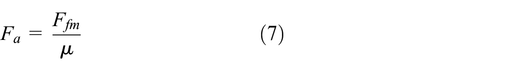
Where
In the force-shape combination constraint mode, the force constraint, namely the active preload Fp and the inertia force FI of the connected piece, should meet the condition: Fp ≥ FI to ensure a reliable connection.
Shape constraint can be divided into bidirectional and unidirectional shape constraints. In a certain DOF direction, if shape constraint can limit the positive and negative bidirectional movement of the DOF, then this shape constraint is bidirectional, and the kinematic pair shape constraint Cpt between the connected piece and the foundation body is bidirectional. If the shape constraint only limits the unidirectional movement of the DOF, and the piece can move in the reverse direction along with the constraint, the shape constraint is unidirectional, and Cct generated by the separation surface contact is a unidirectional constraint, and the combination of the unidirectional constraint and the force constraint can complete the complete constraint.
To sum up, each direction of DOF constraints in the connected separation system need force constraint or force-shape combination constraint, that is force constraints are required in all directions of the DOF constraints, so the separation mechanism in the connected state needs to provide force constraints in six DOF directions. The criterion for determining that the connection state is immovable is:

A point-type separation mechanism can only provide the active force constraint in one direction, and the active force constraint can generate derivative force constraints (such as frictional force constraint) based on the shape constraint. To improve the reliability of the connected separation system, the design principle of the separation mechanism is to use one active force constraint to generate five derivative force constraints (such as frictional force constraints) and provide force constraints in the direction of six DOF.

The point-type separation mechanism is the core component that provides force constraint, which can provide the active force constraint in one direction and produce the derivative force constraint. After applying the active force constraint, the connection function can be realized, and after removing the active force constraint, the separation function can be realized. Therefore, the point-type separation mechanism is the core of the connection separation system.
Comprehensive analysis of point-type separation configuration
The point-type heavy load separation mechanism generally adopts the metal rod with large axial loading capacity as the main force constraint carrier. Point-type separation mechanisms are divided into two categories according to whether structural damage occurs in the separation process. One is to produce structural damage; The other kind of separation mechanism moves relative to each other to achieve the purpose of releasing CF. The two types of point-type separation mechanism are summarized and analyzed, as shown in Table 1, laying a foundation for the design of the separation mechanism.
Schematic diagram of CF release types of typical force constraints of point-type separation mechanism.
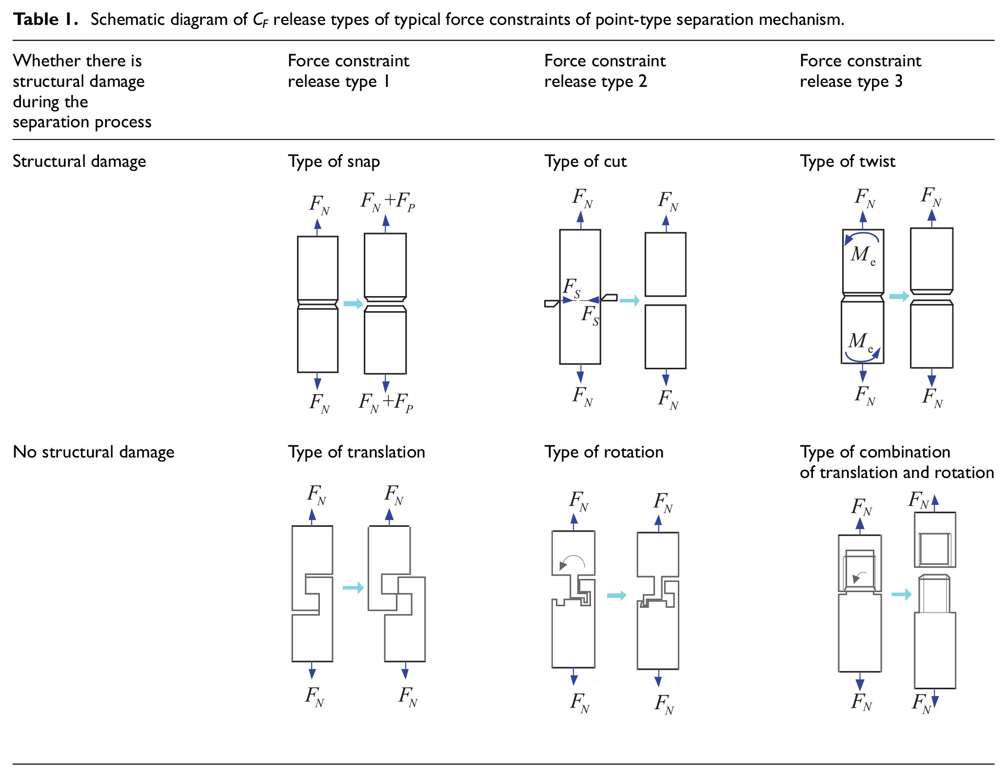
There are three typical ways to release CF by the structural damage of the separation mechanism, which are type of snap, type of cut and type of twist. As shown in Table 1, in the type of snap, additional tension Fp is applied to the separation mechanism in the direction of preload, so that the separation mechanism breaks at the weak spot to release CF. The type of cut, by applying the shear force Fs to the separation mechanism in the direction perpendicular to the preload, the separation mechanism breaks along the shear direction to release CF; The type of twist, by applying torque Me to the separation mechanism in the direction of the preload, the separation mechanism is twisted at the weak spot to remove CF.
The separation mechanism does not have structural damage, and there are three typical ways of releasing CF by the relative motion between the separation mechanism: type of translation, type of rotation, type of combination of translation, and rotation. As shown in Table 1, in the translation type, the separation mechanism releases CF through the relative movement of the translation pair; The type of rotation, the separation mechanism through the relative rotation of the rotation pair releases CF; Type of combination of translation and rotation, the separation mechanism releases CF through the relative motion of the translation pair and the rotation pair.
For the point-type separation mechanism with structural damage, a larger driving force is generally required to destroy the structure of the separation mechanism. There will be huge impact in this separation process, which is inconsistent with the low-impact separation design goal of this paper, so the separation mechanism with structural damage is not the focus of analysis. This paper mainly studies the design method of the low impact separation mechanism without structural damage.
Design of fast separation mechanism with low impact based on energy flow
Analysis of energy flow in separation processof separation mechanism
The connection separation mechanism is mainly composed of trigger mechanism and separation mechanism. The trigger mechanism is mainly responsible for the triggering function of separation action, and the separation mechanism is mainly responsible for the implementation of connection and separation action. The separation mechanism is generally divided into three parts: separation component, energy release component, and fixed component, as shown in Figure 8. During the separation process, the separation components will disengage from the connection separation device and collide with the foundation body. The energy release components absorb energy during separation and release energy in a non-impact or low impact manner. The fixed component is still connected to the foundation body after separation. Energy transfer, conversion and dissipation exist between components in the separation process, which is the source of impact. Based on the movability model of the connected separation system, the energy conservation equation of the separation mechanism was established by using the energy conservation principle and the function principle, and the mechanism design method of reducing the separation impact was explored based on the energy flow idea.
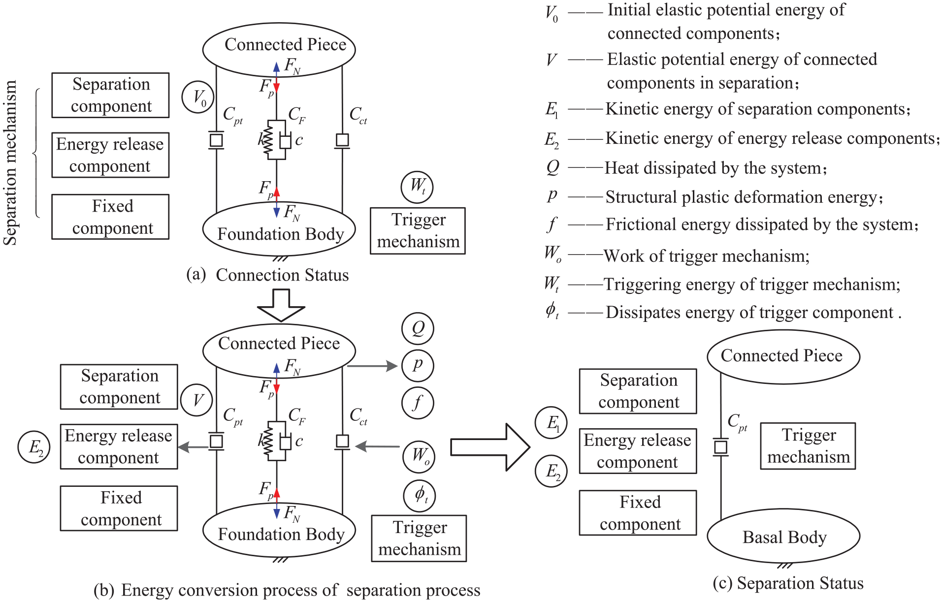
Schematic diagram of the energy flow in the separation process of the separation mechanism.
In the connected state, the separation mechanism presses the connected piece under the action of preload and is in a static state of energy storage. The system energy of the connection separation device is divided into two parts, one is the triggering energy Wt of the triggering mechanism, and the other is the mechanical energy W0 of the separation mechanism, as shown in Figure 8.
In the separation state, taking the trigger mechanism as the research object, part of Wt works on the separation mechanism, and the other part of the energy is dissipated in the process of triggering and driving:

Where Wt is triggering energy of triggering mechanism; We is the work done by the trigger mechanism on the separation mechanism;
In the separation state, taking the separation mechanism as the research object, the mechanical energy of the separation mechanism can be expressed as:

Where W0 is the mechanical energy of the separation mechanism, which is related to the loading capacity; V0 is the elastic potential energy of the separation mechanism; km is the elastic modulus of the separation mechanism; x0 is the elastic deformation of the separation mechanism in the connected state.
The elastic potential energy stored by the separation mechanism is converted into other forms of energy, according to the principle of energy conservation and functional principle, the sum of external force work and dissipation work is equal to the sum of changes in mechanical energy of the separation mechanism, and the obtained energy conservation equation is:

Where
The mechanical energy of the separation mechanism during the separation process can be represented by the elastic potential energy and the kinetic energy of the moving parts:

Where E is the kinetic energy of all moving parts of the separation mechanism during the separation process; V is the elastic potential energy of the separation mechanism during separation.
The energy dissipated by the separation mechanism during the separation process can be expressed as:

Where Q is the total heat energy dissipated by the separation mechanism during the separation process, including the heat energy dissipated by the separation mechanism in the process of forcing, friction and deformation; P is the plastic deformation energy of the separation mechanism structure during the separation process; f is the frictional energy dissipated by the separation mechanism structure during the separation process.
Combining formula s (12), (13), and (14), the energy conservation equation of the separation mechanism is obtained:

Except for W0 in formula (15), all other parameters are functions that change with time. The kinetic energy E of the moving component can be expressed as:

The kinetic energy E of the moving component will be converted into two parts of energy during the separation process, and one part will be converted into the kinetic energy E1 of the separation component, which generally collides with the structure to produce impact; The other part is converted into the kinetic energy E2 of the energy release component, which is generally lost through damping or friction without impact. Formula (16) can be rewritten as:

During the separation process, the energy in the separation mechanism is continuously transformed and dissipated, and the reasonable distribution of the converted and dissipated energy values is an important part of the design of the separation mechanism, it is also an effective means to explore the design method of the separation mechanism. According to formulas (10) and (17), the energy flow analysis of the separation process is carried out, and the energy that may produce the impact is summarized, it can be obtained that We, the separation kinetic energy E1 of the separation component, and the triggering energy Wt of the trigger mechanism can generate impact.
The external force does work We on the separation mechanism is the work done on the separation mechanism during the triggering process of the trigger mechanism. In the pyrotechnic separation mechanism, the pyrotechnic product relies on the chemical energy generated by We on the separation mechanism, causing structural damage to the separation mechanism and a huge impact. However, in the non-pyrotechnic separation process in which the structure of the separation mechanism is not damaged, the We work does not produce impact, or the impact is small. Therefore, it is not considered as a key analysis.
The separation kinetic energy E1 of the separation component is mainly converted from the elastic potential energy of the separation mechanism, and the energy is dissipated through the collision with the foundation structure. The separation shock is generated by the collision of the separation component with kinetic energy with the foundation structure. The smaller the separation kinetic energy E1 is, the smaller the impact is generated.
For the point-type connection and separation mechanism that does not cause structural damage to the separation mechanism, an electric trigger mechanism is generally used. The electric trigger energy Wt is smaller than the separation kinetic energy E1 of the separation component, so this chapter mainly studies the impact caused by the separation kinetic energy E1 of the separation component during the separation process, and the trigger impact is not analyzed.
To explain the relationship between energy and collision impact, the Newton coefficient of restitution method is used to establish the motion equations of the two objects before and after the collision. The collision process of the two objects is shown in Figure 9.


Schematic diagram of the collision.
Where v1n and v2n are the velocities (mm/s) of the foundation body and the separated component before the collision, respectively; V1n and V2n are the velocities (mm/s) of the foundation body and the separated component after the collision, respectively; e is the Newton collision restitution coefficient.
According to the law of conservation of momentum:

Where m1 is the mass of the foundation body (kg); m2 is the mass of separation component (kg).
Combining formulas (18) and (19), the impact impulse of the collision is obtained:

Where Pn is the impact impulse of the collision (Ns).
During the collision:

Where Fp is the collision force (N).
The impact of the separation process is generated by the collision force, and the impact on the foundation body can be expressed as:

Taking the foundation body as the reference target, the initial velocity v1n of the foundation body is 0 mm/s, and simultaneous formula s (22), (21), and (22) can be obtained:

It can be seen from formula (23) that under the condition of a certain separation time, the impact a1 in the separation process is proportional to the speed v2n of the separation component before the collision and is positively related to the separation kinetic energy E1 of the separation component. Therefore, the way to reduce the separation impact under the constraints of rapid separation is to reduce the separation kinetic energy E1 of the separation components, and the subsequent energy conversion method will reduce the separation kinetic energy of the separation components.
Energy conversion principle of low impact separation configuration
Through the analysis of the energy flow of the separation mechanism, it is found that the main cause of the separation shock is the separation kinetic energy E1 of the separation component. The separation mechanism design method based on energy flow analysis mainly aims at low impact separation, and designs low impact separation mechanism according to the energy conversion principle of mechanical system. In a mechanical system, each component unit has the function of storing energy and releasing energy. If there is a force interaction between the two component units in the direction of motion, the energy will flow. Taking the two interacting components as an example, the energy flow process of the mechanical system is described.
In a mechanical system, an interaction force is generally generated between two components through a kinematic pair, thereby transferring energy and motion. The two components are connected by a kinematic pair, as shown in Figure 10, with the same motion speed. When two components interact with each other, the interaction force is generated by contact of point, line or plane at the kinematic pair, and the contact surface can be replaced by a spring damping model.

Schematic diagram of two-components energy conversion: (a) spring compression stage and (b) spring tension stage.
In the spring compression stage, as shown in Figure 10(a), the moving directions of component A and B are both in the positive direction of the x-axis, and component B applies the elastic force FA in the negative direction of the x-axis to component A, the component A applies the elastic force FB in the positive direction of the x-axis to the component B. The direction of the speed vA of component A is opposite to the stress on component FA, the elastic force does negative work on component A, and the energy of component A flows out. The direction of the speed vB of component B is the same as the force FB, the elastic force does positive work on component B, and the energy of component B flows in. In this process, due to the interaction force between component A and component B in the direction of motion, energy flow occurs, and energy flows from component A into component B. In the spring stretching stage, as shown in Figure 10(b), component A and component B move along the positive x-axis direction. Component B applies a positive x-axis elastic force FA to component A, and component A applies a negative x-axis elastic force FB to component B. The direction of the speed vA of component A is the same as the force FA, the elastic force does positive work on component A, and the energy of component A flows in. The direction of the speed vB of component B is opposite to the force FB, the elastic force does negative work on component B, and the energy of component B flows out. In this process, due to the interaction force between component A and component B in the direction of motion, energy flow occurs, and energy flows from component B into component A.
The energy conversion process in the two-components energy conversion model can be extended to the general mechanical system. If there is an interaction force between two components, and there is displacement in the direction of the interaction force, then the two interaction forces must do work for the components. Since the mutual force is equal in magnitude and opposite in direction, and the displacement of the two components is equal, the mutual force does positive work to one component and negative work to the other component, and the positive work is equal to the absolute value of negative work. The energy out of one component is equal to the energy inflow of the other component. To sum up, in the case of no external force, there is the mutual force between the two components in the direction of motion, then the energy will flow from one component to the other, and the total energy of the two components is conserved without considering the damping loss.
In the connection separation task, the separation kinetic energy E1 of separation components is reduced by energy conversion to achieve the purpose of low impact separation. The idea of energy conversion is: if there is interaction force between two components in relative motion direction, then there is energy flow and conversion between the two components. In the separation process of the separation mechanism, the separation kinetic energy E1 of the separation component can be converted into the kinetic energy E2 of the energy releasing component, which can be dissipated by impact energy I, friction energy F or damping energy C, or converted into elastic potential energy V2 for storage. To sum up, the idea of energy release in the separation process of the separation mechanism using the energy conversion principle is that the kinetic energy E1 of the separation component is efficiently converted into the kinetic energy E2 of the release component.
The energy conversion principle of mechanical system and the design idea of the separation mechanism can be used to design the separation mechanism. The energy conversion law between two components is analyzed and judged from the Angle of kinematics and mechanics, which lays a foundation for innovative design of separation mechanism.
Separation configuration design based on energy conversion principle
According to the principle of energy conversion, the design idea of the separation mechanism was obtained, and the detailed design of the separation mechanism was carried out based on the modified design idea. According to the energy conversion law of two components, the contact force between the energy releasing component and the separated component is the basis to judge the energy conversion. The separation surface is defined as the contact surface between the separation component and the energy releasing component or the fixed component. According to the included Angle α between the direction of release surface and the direction of preload, there are three typical contact modes of release surface: vertical release surface, oblique release surface and horizontal release surface, as shown in Figure 11 (Tables 2 and 3).

Schematic diagram of three typical contact modes of separation surfaces: (a) vertical escape surface, (b) oblique escape surface, and (c) horizontal escape surface.
Analysis of three typical contact modes of separation surfaces.

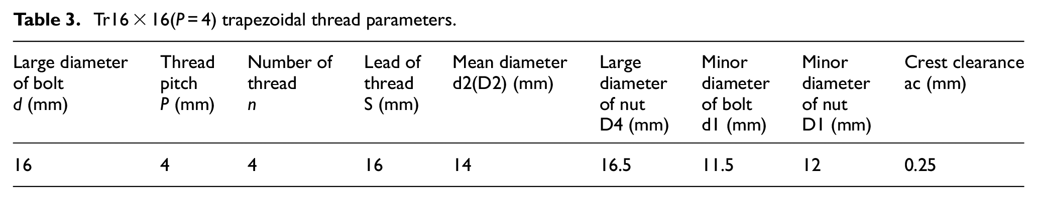
Tr16 × 16(P = 4) trapezoidal thread parameters.
When the heavy load separation mechanism is connected, the separation mechanism stores huge elastic potential energy, and the stored elastic potential energy is used as the input energy for separation of the separation mechanism. It is one of the principles of mechanism design to be able to complete autonomous separation. As shown in Figure 11(a), the direction of the preload force FP is parallel to the direction of the separation surfaces. When the y-direction translation constraint
From the analysis of the contact modes of the three typical separation surfaces in Figure 11, it can be obtained that only when the angle

Schematic diagram of the contact method of the thread separation surface: (a) linear motion of the energy release unit, (b) rotational motion of the energy release unit, (c) rotational motion of the combination, and (d) thread pair.
As shown in Figure 12(a), the energy release unit contacting the oblique separation surface can move along the x-axis guide rail to release the x-direction constraint
Heavy load connection and low impactfast separation device design
Working principle and device composition of non-self-locking thread separation mechanism
To meet the requirements of heavy load connection separation for large loads such as satellites, a connection separation device with a loading capacity of more than 100 KN and separation impact of less than 500 g was designed to realize millisecond separation, and a general design method based on energy flow was verified. 23 The mechanism can meet the future requirements of low impact separation for rocket stage separation, satellite and arrow separation, large cabin separation and so on. The working principle of the device is shown in Figure 13.

Working principal diagram of the separation device: (a) connection state and (b) separation state.
Based on the goal of efficient energy flow conversion, a thread pair separation mechanism with orthogonal energy conversion was obtained. The detailed mechanical design of core separation mechanism such as thread, bolt, nut, and shafting are completed for low impact and fast separation of heavy load connection. SMA wire trigger secondary swing arm as low impact trigger source, the flywheel nut which can efficiently absorb the kinetic energy of bolt storage and separation is used as an energy release component, formed a flywheel non-self-locking thread pair separation mechanism scheme, this scheme can meet the heavy load connection and low impact rapid separation task requirements.
Heavy load energy storage connection: The heavy load connection is realized by applying preload to the loading bolt of the separation mechanism, so that the loading bolt can generate elastic potential energy V0. The preload is transferred to the flywheel nut to generate rotational potential energy, and the locking load is further transferred to the SMA mechanism. According to the principle of torque balance, the locking load is gradually reduced to the range of SMA trigger ability. At this time, the SMA mechanism can maintain the rotational potential energy of the flywheel nut in the locked state. When in the mechanical environment of the launching section, the additional tensile load borne by the separation mechanism is also transmitted through this path and method.
Energy conversion and separation: When the SMA mechanism triggers the separation, lifting the limit of the release energy assembly flywheel nut, flywheel nut high-speed rotation to transfer its stored rotational potential energy into kinetic energy, and with the bolt movement and friction in the thread pair to consume kinetic energy, to achieve low impact separation goals.
Heavy load connection and low impact separation device is mainly composed of SMA trigger mechanism and separation mechanism. The mechanism and composition are shown in Figure 14.

Schematic diagram of the separation device.
The separation mechanism is the main part of the device to bear the connection constraint, which consists of the main bearing screw and flywheel nut. When the limit of the flywheel nut is lifted, the nut rotates to push the main bearing screw to move in a straight line in the direction of separation, to realize the separation of the connected piece. When the flywheel nut is separated, because the circumferential rotation constraint is released, the elastic potential energy will be dissipated by high speed rotation under the action of the driving torque generated by the elastic potential energy, thus reducing the separation kinetic energy of the screw, and finally achieving the goal of low impact separation. Thread pair is the core part of the separation mechanism, and its characteristics directly affect the performance of the separation mechanism. Under the constraint of heavy load connection, the principle of thread selection is large loading capacity, large radial separation force. The design of non-self-locking thread connection between main bearing screw and flywheel nut is the core of the whole mechanism design. To achieve the goal of conversion from linear motion to circumferential motion and efficient energy conversion, it is also necessary to meet the requirements of large axial load and transmission, so the trapezoidal non-self-locking thread mechanism is selected.
Based on the selected thread type, the thread pair is designed according to the separation performance index. The mechanism design follows the principle of non-self-locking, fast separation and small dynamic envelope, so large rise angle, large lead and multi-thread thread are selected. Under the premise of ensuring the strength of loading capacity, increase the angle of the thread as far as possible to ensure that the friction resistance between the main bearing rod and the main bearing nut can be successfully overcome. The other end is matched with the thin tooth thread of the loading nut to ensure sufficient connection strength and form a self-locking connection with the loading nut to achieve reliable loading and maintenance of preload force. The hexagonal section of the bearing rod is matched with the hexagonal slot of the limited mounting seat to limit the circumferential rotation of the bearing rod, avoiding the preload unloading of the screw and ensuring that the screw can only move in a straight line along the direction of separation without rotating with the nut.
Energy conversion analysis of separation mechanism
The separation mechanism of flywheel non-self-locking thread pair can efficiently transform the kinetic energy of the separation component into the kinetic energy of the release component, thus achieving the purpose of heavy load connection and low impact separation. The energy conversion efficiency from the separation component to the energy release component is an important index for evaluating the separation mechanism and a decisive factor for low impact separation. Therefore, the energy conversion efficiency of the flywheel non-self-locking thread pair separation mechanism is analyzed by combining calculation and simulation.
It is known that the elastic potential energy provided by the loading nut during the loading preload is:

Where
The friction resistance work of the non-self-locking thread pair is:
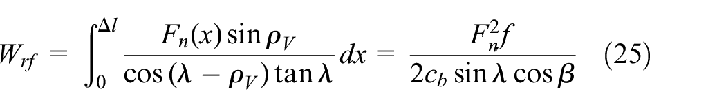
Where x is the separation length of the device (mm);
The frictional impedance work of thrust roller bearing can be expressed as:

Where
The energy equation of nut loading can be obtained:

Where
If the average angular velocity of flywheel nut during separation is, then the average axial velocity of screw is:
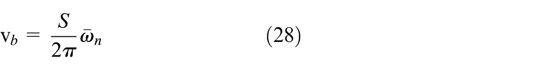
Then the separation time is:

Where L is the length of the screw (mm); S is the lead of non-self-locking thread (mm).
Table 4 shows the parameter values of the designed flywheel non-self-locking thread pair separation mechanism.
Parameters of separation mechanism.
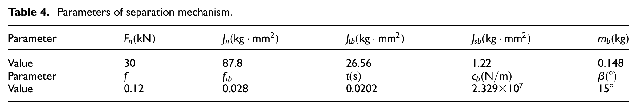
Substituting the above data into formulas (29), (30), and (31), it can be obtained that when the preload of the nut is 30 kN at room temperature of 20°C, the angular velocity of the nut

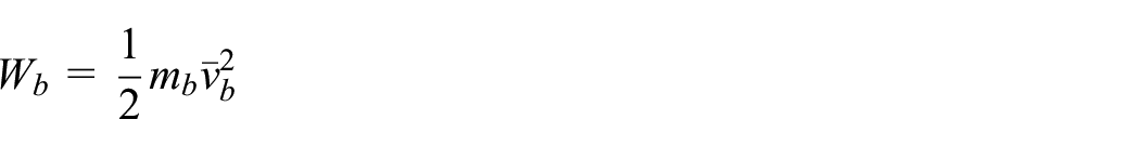
It can be concluded that the energy Wn of the nut of the energy-releasing assembly is 19.148 J, and the energy Wb of the screw of the separation assembly after energy conversion is 0.0895 J, so the energy conversion efficiency can be expressed as:

According to the energy conversion efficiency η of the separation mechanism, it can be concluded that the designed non-self-locking thread pair separation mechanism can effectively realize the energy conversion efficiency from the screw of the separation component to the flywheel nut of the energy release component in the separation process, and the conversion efficiency reaches 99.5%. The design method of low impact and fast separation mechanism based on energy flow was verified, and it was proved that the mechanism could realize low impact and fast separation under the condition of heavy load connection.
Conclusion
This paper proposed a separation mechanism design method based on energy flow and carried out the design and optimization of the separation mechanism from the perspective of energy transfer and conversion. The summary is as follows:
Established the movability model of the connection separation system and put forward the movability criterion of the connection separation. Aiming at applying and releasing force constraints, the separation principle of separation mechanism was analyzed.
The energy flow model in the separation process of the separation mechanism was established, and the guiding ideology of energy flow was proposed with low impact separation as the design goal. The energy conversion model of two components in mechanical system was established, the conditions of energy conversion of two components was analyzed, and a thread pair separation mechanism with efficient energy conversion was designed.
The separation mechanism and trigger mechanism were designed with the aim of fast separation, heavy load, and low impact. A flywheel non-self-locking thread pair separation mechanism was proposed, the energy conversion efficiency and low impact target were verified by energy conversion calculation.
Footnotes
Handling Editor: Chenhui Liang
Declaration of conflicting interests
The author(s) declared no potential conflicts of interest with respect to the research, authorship, and/or publication of this article.
Funding
The author(s) disclosed receipt of the following financial support for the research, authorship, and/or publication of this article: G. Wang would like to thank the financial support from the Natural Science Foundation of Hebei Province (Project No. E2021409025), the S&T Program of Hebei (Project No. 21375414D), Scientific Research Project of Higher Education Institutions of Hebei Province (Project No. QN2022123), The Central Guidance on Local Science and Technology Development Fund of Hebei Province (Project No. 226Z1803G), the Langfang Municipal Science and Technology Program Self-financing Project (Project No. 2021011068) and the PhD research startup foundation of North China Institute of Aerospace Engineering (Project No. BKY-2021-11). J. Wang acknowledges the financial support from the Hebei Province Graduate Innovation Funding Project (Project No. CXZZSS2022133) and the Postgraduate Innovation Funding Project of North China Institute of Aerospace Engineering (Project No. YKY-2021-23). Y Yao thanks the support of the Postgraduate Innovation Funding Project of North China Institute of Aerospace Engineering (Project No. YKY-2021-22).