
Abstract
The film stiffness of gas-lubricated hydrostatic bearings and seals are considered to be enhanced remarkably by proper design of a diaphragm-type restrictor. A fluid-structure coupling numerical model by coupling iteration of small deflection bending differential equation of circular thin plate and one-dimensional Reynolds equation was established, and the influence of different parameters, including pressure and geometrical parameters, on the flow output characteristics of a diaphragm-type restrictor was investigated numerically and experimentally. The results show that the correctness of established fluid-structure coupling numerical model is verified well by comparing calculated values of diaphragm deformation and output flow characteristics to the measured values. The optimum values of diaphragm thickness is 0.6–0.8 mm and initial throttle clearance is 20–35 μm for stable operation of diaphragm-type restrictor, while the optimum value of back pressure strongly depends on the diaphragm thickness.
Keywords
Introduction
Dry gas seal (DGS), as a typical kind of noncontacting mechanical seal, meets satisfactorily the requirements of low leakage rate, wear-free operation, and low power consumption for industrial centrifugal compressors, pumps, fans and other turbomachines with medium speed, which includes hydrodynamic and hydrostatic type.1–3 The gas film stiffness of DGS and thrust bearing is strongly dependent on the geometry of the supply system, that is, restrictor.4–6 However, it is difficult for the classical fixed orifice restrictor to adjust the geometrical structure according to the variation of external conditions, resulting in poor gas film stability. On this basis, variable restrictors, including diaphragm-type and spool-type restrictor,7–9 are proposed for making up this shortcoming and obtaining relatively large gas film stiffness.10,11
Many scholars have conducted a lot of research on diaphragm-type restrictor. Kang et al.9,12 analyzed the static stiffness of hydrostatic bearing with two typical variable throttle devices: diaphragm-type and spool-type restrictor, and discussed the influence rule of throttle structure parameters on its performance. In addition, by changing the outlet pressure of load-regulated throttle, Kang et al. 13 proposed a method to identify the restrictive and deformation parameters of diaphragm-type restrictor by replacing the measured values of inlet pressure, outlet pressure and flow with the combined equation. Ghodsiyeh et al.14,15 proposed a diaphragm-type restrictor with a customized control valve and proved that an appropriate initial value can make the diaphragm-type restrictor throttle have infinite stiffness by applying step force tests. Lai et al. 16 optimizes two important design parameters, including diaphragm stiffness and throttle ratio of bearing system, of a diaphragm-type restrictor for obtaining maximum static bearing stiffness. Chen et al. 17 performs the fluid-structure interaction analysis of the diaphragm to obtain pressure and stress field distribution, and the deformation of diaphragm in membrane restrictors by using COMSOL. Singh et al. 18 describes a theoretical study concerning the performance of an externally pressurized multi-recess hydrostatic/hybrid flexible journal bearing system by varying the geometric shape of recess and using the membrane flow valve restrictor as a compensating element. Gohare et al. 19 investigates the static characteristics of a water-lubricated hydrostatic thrust bearing using a membrane restrictor to achieve higher stiffness and lower power consumption at high speeds.
A thorough scan of the literature pertaining to the performance of diaphragm-type restrictor reveals that most of the literatures aim at studying design and parameter influence law, numerical analysis model and high-efficiency numerical algorithm, etc. However, there is little report on the effect of different parameters on the fluid-structure coupling performance of a diaphragm-type restrictor and the establishment of a fluid-structure coupling model for mutual verification of theory and experiment. Hence, the present work is aimed to study the influence of different geometrical and pressure parameters on the output characteristics of a diaphragm-type restrictor by establishing the fluid-structure coupling model, and verify the accuracy of the coupling model experimentally.
Fluid-structure coupling model of diaphragm-type restrictor
Geometrical structure and working principle
Figure 1 shows the geometric structure and key parameters of a typical diaphragm-type restrictor. The main structure of the diaphragm-type restrictor is a circular elastic diaphragm clamped between the back pressure chamber and the throttling chamber with a thickness of t. Above the diaphragm is a back pressure chamber filled of pressurized gas with pressure p3. An annular throttling channel with initial clearance h0 is formed between the lower part of the diaphragm and the end face of the throttling nozzle. The inner side of the annular throttling channel connects with the nozzle hole with radius r1, and the gas with pressure p1 flows out from the nozzle hole and flows into the throttling channel. The outside of the throttling channel connects with the throttling outlet with inner radius r2, outer radius r3 and pressure p2. Moreover, the throttle outlet connects with the hydrostatic seal or bearing clearance, so the pressure change in the bearing or seal clearance will feed back and affect the outlet pressure of the diaphragm-type restrictor. The elastic diaphragm will be elastically deformed under the joint action of the pressure differential between the two sides of the diaphragm. Since the elastic diaphragm is pressed tightly around, it can be regarded as a circular thin plate with fixed support around it, and the maximum deformation f is at the center of the diaphragm. The deformation of the diaphragm center can be measured by the displacement sensor fixed at the center of the upper back pressure cavity The value of diaphragm deformation is positive when it aways from the end face of the throttling nozzle, otherwise it is a negative one. The nozzle is fixed on the nozzle seat by thread, the nozzle seat can be also connected with the lower throttling cavity through thread, and thus the initial throttle clearance h0 can be adjusted by adjusting the axial displacement of the nozzle seat.
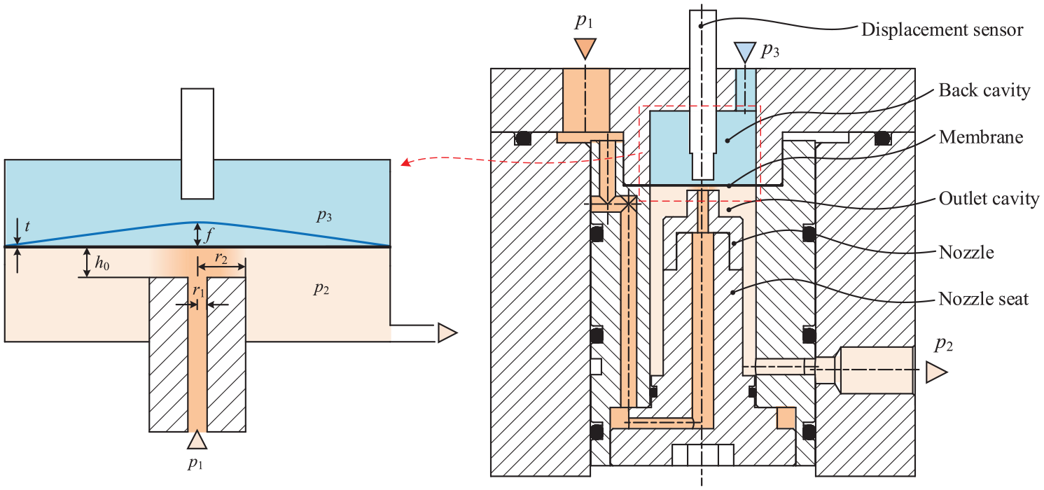
Structure diagram of a diaphragm-type restrictor and its key geometrical parameters.
The interaction between the fluid pressure and the elastic diaphragm deformation in the diaphragm-type restrictor is a typical two-way fluid-structure coupling problem. Figure 2 presents the schematic diagram of the fluid-structure coupling model of the diaphragm-type restrictor and its influence parameters. The throttle outlet pressure p2, diaphragm deformation f and throttle clearance h0 are the three basic elements of the fluid-structure coupling model, the coupling relationship of which is shown as: the change of the outlet pressure p2 leads to the diaphragm deformation and then change the shape of the throttle clearance, which furtherly change the flow resistance and pressure drop on the throttle channel, then feedback and affect the pressure and gas flow at the outlet of the throttle. The throttle clearance h is determined by the initial throttle clearance h0 and the diaphragm deformation f. The diaphragm deformation is not only affected by the inlet and outlet pressure, but also affected by the back pressure p3, diaphragm parameters (diaphragm thickness and Young’s modulus), and nozzle parameters (outer radius and inner radius). The pressure distribution of gas in throttling channel can be described by the one-dimensional compressible Reynolds equation. The gas flow rate qv at the outlet of the throttling channel, the product of gas velocity and outlet area, can be calculated according to the given inlet pressure, outlet pressure and the throttling clearance. The flow velocity in the whole throttling channel should be lower than the local acoustic velocity, in other words, Mach number should be smaller than 1, which is used to determine the minimum outlet pressure p2min.

Fluid-structure coupling model of the diaphragm-type restrictor and its influence parameters.
Numerical solution of elastic diaphragm deformation
For the elastic diaphragm is pressed tightly around, it can be regarded as a circular thin plate with fixed support around it. Considering that the adopted diaphragm thickness is generally sub millimeter (0.2–0.8 mm), and the deformation of diaphragm is generally about tens of microns. Hence, the deformation deflection of the diaphragm f can be calculated by the small deflection bending differential equation of the circular thin diaphragm under axisymmetric transverse load:

where Qr is the shear force per unit length, and D is the bending stiffness:
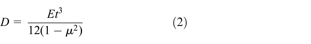
where E and μ are the Young’s modulus and Poisson’s ratio of the diaphragm, respectively.
For a circular elastic thin diaphragm with radius R, if it is only subjected to the uniformly distributed load p on the circular area with radius a, the unit length shear Qr in different radial areas can be expressed as:

Submitting equations (2) and (3) into equation (1), and considering the deflection and corner boundary conditions: both the deflection and angle are 0 when at the peripheral fixed support r = R, the inner and outer deflection, both the first derivative and second derivative of deflection are equal when at the local load boundary, and the corner angle is 0 when r = 0. The formula for calculating the deflection of diaphragm subjected to uniformly distributed load p within the radius r = a can be obtained as:
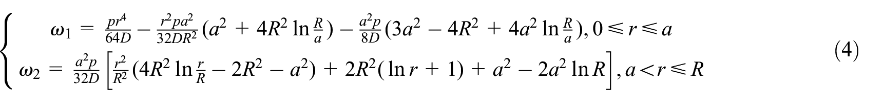
Figure 3 depicts a simplified diagram of the circular thin diaphragm under radial variable load. In fact, the pressure acts on the elastic diaphragm along the radial direction is not a uniformly distributed load, but a gradually decreasing load p(r) along the radial direction from the throttling inner chamber to the outer chamber, as shown in Figure 3(a). For the circular elastic diaphragm with uniformly distributed pressure p3 on the upper part and variable load p(r) on the lower part, the pressure can be simplified as no pressure on the upper part and variable load p(r)−p3 on the lower part, as presented in Figure 3(b). The pressure acts on the circular diaphragm can be divided into two parts: one is the uniformly distributed pressure load p2−p3 for the region with r > r2, and the other is the radial variable pressure load p(r) for the region with r1 < r < r2. Figure 3(c) provides a method of superposition of loads: dividing the nozzle end face along the radial direction to n parts with an equal spacing Δr, then the variable load p(r) on the nozzle end face can be transformed into the superposition of uniformly distributed pressure loads p(r)−p(r + Δr) at different radial positions. For the uniformly distributed pressure load of p2−p3 in region r > r2, the deflection of the diaphragm ω0 can be calculated according to equation (4). For the diaphragm deflection ω1 caused by the variable load in the region r1 < r<r2, the diaphragm deflection ωa= r under micro pressure load p(r)−p(r + Δr) is firstly calculated based on equation (4), the deflection of the diaphragm ω1 is then superimposed by the deflection of the diaphragm caused by the micro-pressure load at different radial positions, and the total deflection of diaphragm is ω = ω0+ω1, as shown in Figure 3(d).

Simplified diagram of force on circular sheet subjected to radial variable load : (a) load on elastic diaphragm, (b) equivalent load distribution, (c) load superposition method, and (d) diaphragm deflection superposition.
Solving pressure distribution based on one-dimensional Reynolds equation
For the circular annular throttle channel distributes uniformly along the circumferential direction, the flow law of pressurized gas can be described by one-dimensional compressible Reynolds equation based on laminar flow assumption:

where r and h are the radius and clearance of the throttle channel, respectively, and p is the gas pressure.
The Reynolds equation shown in equation (5) is discretized by the finite difference method, the gas pressure pi at any point ri on the nozzle end face can be calculated from the pressure pi−1 and pi+1 at adjacent points:
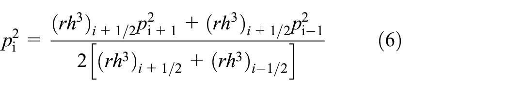
where

Mandatory pressure boundary condition exists at the inner radius r = r1 of nozzle end face, that is, gas film pressure p = p1. There is a blocking pressure boundary condition at the outside radius r = r2 of the nozzle end face, and the gas film pressure p = p2. However, p2 needs to be larger than the minimum blocking pressure p2min, the value of which can be determined by the maximum gas velocity which should not exceed the local sound velocity in throttle clearance.
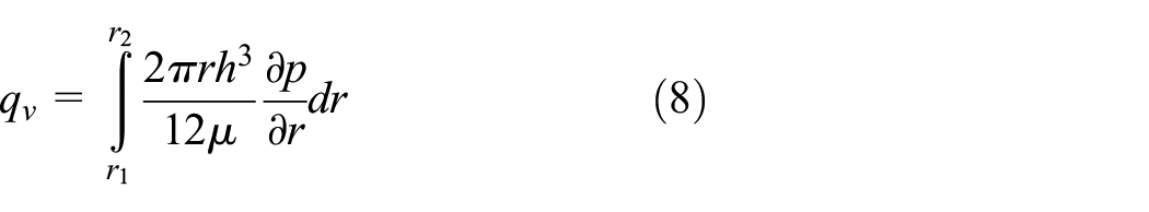
Combining the above-mentioned pressure boundary conditions, the gas pressure distribution p(r) and the gas radial velocity vr in the annular throttle clearance can be obtained, and the gas volumetric flow qv through the throttle channel can be further obtained:
Fluid-structure coupling calculation flow
The flow chart of the fluid-structure coupling calculation of a diaphragm-type restrictor is depicted in Figure 4. Setting outlet pressure p2 and pressure distribution of throttle clearance based on given pressure and structure parameters, diaphragm deformation can be obtained by solving equation (4) when it needs to be considered. The sum of the diaphragm deformation f(r) and the initial throttle clearance h0 is the actual throttle clearance h(r). However, it should be noted that the negative deformation of the diaphragm must not exceed the initial throttle clearance, if it does, increase the outlet pressure p2 and recalculate it. Actual throttle clearance h(r) = h0 if diaphragm deformation is out of considered. The gas pressure distribution p(r) and Mach number distribution Ma(r) in the throttling channel are obtained by solving the one-dimensional compressible Reynolds equation shown in equation (5), and judge whether the maximum Mach number is less than 1, if not, increase the outlet pressure p2 and recalculate the diaphragm deformation and pressure distribution. The fluid-structure coupling simulation process of the diaphragm-type restrictor would be end when both the diaphragm deformation and the maximum Mach number are satisfied, then the parameters such as diaphragm deformation, outlet pressure and volumetric flow can be output.

Flow chart of fluid-structure coupling calculation program of a diaphragm-type restrictor.
Test platform
Figure 5 demonstrates a test rig for the diaphragm-type restrictor. The test rig is an important tool for verifying the correctness of the fluid-structure coupling model and studying the diaphragm deformation and flow characteristics. The performance test platform for the diaphragm-type restrictor includes the thin diaphragm-type throttle body, three gas lines and parameter acquisition system, of which three gas lines are: inlet pressure gas line II, outlet pressure gas line III and diaphragm back pressure gas line I. Each gas line is equipped with a pressure regulating valve 1, a digital pressure gauge 2, a pressure transmitter 3, and a pneumatic connector 4. A gas flowmeter 5 is installed on the gas line III among them. There are pneumatic connectors II-4 for gas line II and I-4 for gas line I at the center and eccentric of the back pressure cavity body respectively, pneumatic connector III-4 for gas line III at the side of the throttle cavity body. Displacement sensor 6 at the side of the nozzle seat to monitor the axial displacement of the nozzle seat and to reflect the change of the initial throttle clearance indirectly. During the experiment, the output signals from pressure transmitters I-3, II-3, and III-3, gas flow meter III-5 and displacement sensor 6 are collected by data acquisition card and sent to computer for display and processing.
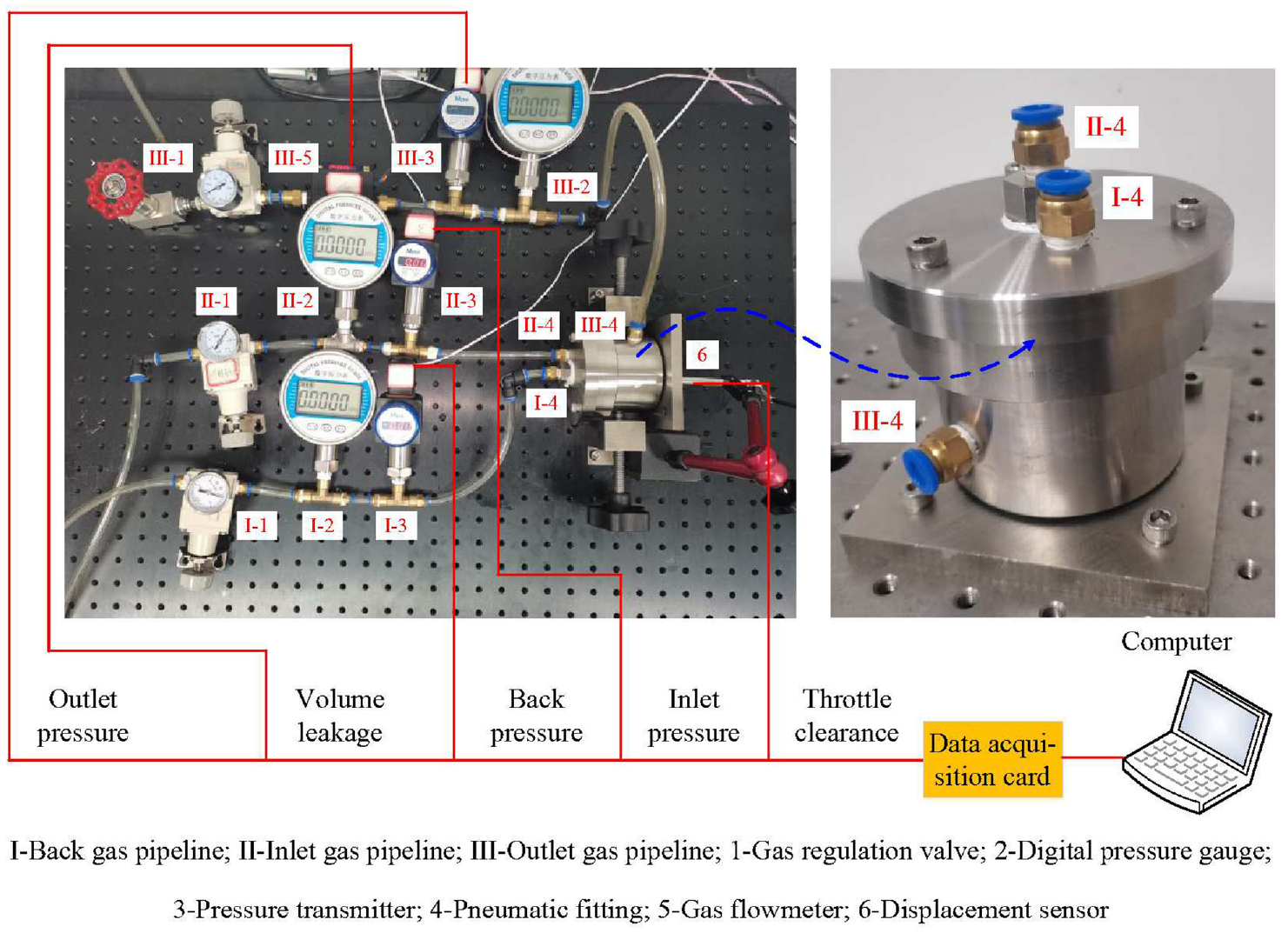
Physical map of the diaphragm-type restrictor test system.
The performance of a diaphragm-type restrictor is very sensitive to the change of initial throttle clearance, which is usually only tens of microns. The key to measuring performance of a diaphragm-type restrictor precisely is to achieve both precise adjustment and measurement of initial throttle clearance. Figure 6 presents the schematic diagram of the adjustment scheme of the initial throttle clearance in the fixed and variable throttle clearance state, respectively. As shown in Figure 6(a), replacing the elastic diaphragm with the matching ring threaded into the back pressure chamber as the counterpart to the end face of the nozzle when on the fixed throttle clearance state. When studying the flow state of gas through a fixed clearance without considering the diaphragm deformation, the throttle clearance can be regarded as 0 when the end face of matching ring and nozzle are in contact. The throttle clearance increases gradually by twisting the matching ring and moving it axially away from the end face of the nozzle. The throttle clearance can be measured by a displacement sensor in contact with the other end face of the pairing ring. As shown in Figure 6(b), displacement sensors are installed at the bottom of the nozzle seat and at the back pressure chamber side of the elastic diaphragm to monitor the axial displacement of the nozzle seat and the deformation of the elastic diaphragm, respectively, for the purpose of verifying and studying the fluid-structure coupling relationship between the elastic diaphragm and gas flow on the throttle clearance. Firstly, making the nozzle seat to move close to the diaphragm until the reading of the displacement sensor above the elastic diaphragm begins to change. At this time, it can be considered that the end face of the nozzle is just in contact with the elastic diaphragm. Then making the nozzle seat away from the diaphragm and the reading of displacement sensor at the bottom of the nozzle seat changes as the initial throttle clearance value.

Schematic diagram of initial throttling clearance adjustment scheme of the diaphragm-type restrictor: (a) adjusting counterpart and (b) adjusting nozzle mount.
An elastic diaphragm radial deformation test platform is designed to verify the accuracy of the diaphragm deformation test, as depicted in Figure 7. The displacement sensor is fixed on a displacement platform by a magnetic base and the probe of the displacement sensor contacts with the surface of the elastic diaphragm. Adjusting the displacement platform along the diaphragm radial direction to change the position of the displacement sensor probe, which enables measure the radial deformation of elastic diaphragm. Hence, it overcomes the shortcoming that fixed displacement sensor can only measure the center deformation of elastic diaphragm.

Schematic diagram of a test rig used for measuring radial deformation of the elastic diaphragm.
Results discussion and analysis
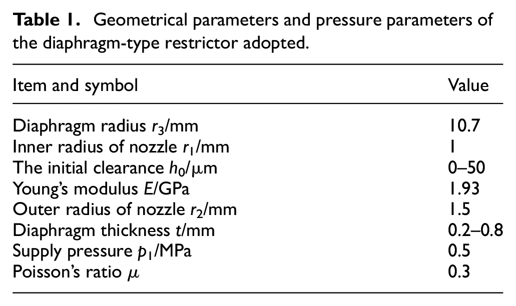
Gas flow characteristics and diaphragm deformation laws under parallel and variable throttle clearance were studied numerically and experimentally. Table 1 provides an illustration of the default values of the geometrical and pressure parameters used for diaphragm-type restrictor analysis, in which the inner radius r1 and the outer radius r2 of the nozzle end face are 1.0 and 1.5 mm, respectively. The diaphragm outer radius is r3 = 10.7 mm, the inlet pressure is p1 = 0.5 MPa, the diaphragm thickness t ranges from 0.2 to 0.8 mm, and the initial clearance h0 ranges from 0 to 50 μm. If not specified, the parameters involved below are selected according to the above parameters.
Geometrical parameters and pressure parameters of the diaphragm-type restrictor adopted.
The change law and verification of diaphragm deformation
Considering that the formula for calculating the deformation of elastic diaphragm in this paper is based on the theory of small deflection deformation of thin plate, the applicability of which needs to be verified when the deformation is close to or even more than 20% of the diaphragm thickness. Without considering the effect of gas throttling in the throttle clearance, the outlet pipeline on the throttle chamber is blocked, that is, the gas pressure on one side of the diaphragm is uniformly distributed to verify the correctness of the diaphragm deformation calculation formula. Figure 8 depicts the central and radial deformation of the elastic diaphragm under different inlet pressure. The diaphragm center deformation increases linearly with the increases of inlet pressure, while the diaphragm central deformation decreases gradually with the increases of diaphragm thickness. The largest value of diaphragm central deformation is fmax = 73 μm when t = 0.4 mm and p1 = 400 kPa. Under the given inlet pressure and diaphragm thickness, the numerical calculation results of diaphragm deformation agree well with the test values, which verifies the correctness of formula (4) in calculating diaphragm deformation. The diaphragm deformation gradually decreases from the center along the radial direction outwards under the inlet pressure p1. The simulated and experimental values of the diaphragm deformation are close to each other near the diaphragm center, while the measured values of the deformation far away from the diaphragm center are slightly higher than the simulated ones, which may be due to the inclination of the displacement platform along the moving direction.

Variation law of diaphragm deformation with different diaphragm thickness: (a) central deformation and (b) radial deformation.
Flow characteristics on parallel throttling clearance
To verify the correctness of predicting the flow characteristics on the throttle clearance of a diaphragm-type restrictor based on the compressible Reynolds equation, a rigid paired ring is used instead of the elastic diaphragm as shown in Figure 6(a) to construct a parallel throttle clearance. The output pressure and gas flow rate under different throttle clearance are investigated. The volumetric flow formula for circular slab clearance can also be calculated by:

Figure 9 is a plot of the outlet pressure and volumetric flow of parallel throttle clearance under different throttle clearance when the inlet pressure p1 = 400 kPa. Outlet pressure increases rapidly with the increases of throttle clearance, that is, it is very sensitive to the change of throttle clearance when h = 5–20 μm, while the increase rate tends to slow when h > 20 μm. On the one hand, the pressure drop of gas should not be too large to avoid excessive energy loss. On the other hand, to avoid excessive fluctuation of gas pressure in downstream bearings or seals, the initial throttle clearance of the film throttle should be h > 20 μm. The measured values of outlet pressure agree well with the calculated values under different throttle clearance, which verifies the accuracy of the solution of fluid flow characteristics in throttle clearance based on one-dimensional compressible Reynolds equation, while the calculated value is slightly less than the measured value when h0 > 10 μm. As shown in Figure 9(b), the volumetric flow increases approximately linearly with the increases of throttle clearance. The calculated value of flow based on Reynolds equation is slightly larger than the measured one, and the error between which is not more than 0.3 L/min. This is the smaller outlet pressure calculated value which leads to the larger calculated values of both differential pressure and volumetric flow. In summary, the outlet pressure is no longer sensitive to the change of throttle clearance when h > 20 μm, while the gas flow is still very sensitive on the whole range of given throttle clearance. It should be noted that the downstream regulation of a diaphragm-type restrictor is mainly reflected in the volumetric flow, so the initial clearance should not be less than 20 μm.

Flow characteristics in parallel throttling clearance at different initial clearance: (a) outlet pressure and (b) volumetric flow.
Fluid-structure coupling characteristics without back pressure
The outlet pressure and central diaphragm deformation of the diaphragm-type restrictor with different initial throttle clearance and diaphragm thickness under back pressure p3 = 0 and the inlet pressure p1 = 405 kPa were studied as depicted in Figure 10, to verify the correctness of the fluid-structure coupling model for diaphragm-type restrictor. As the increases of the initial throttle clearance, the outlet pressure increases slowly and approaches the inlet pressure at a relatively large initial clearance, while the diaphragm deformation changes little. With the increases of diaphragm thickness, both outlet pressure and diaphragm deformation decrease gradually. The decreasing outlet pressure is caused by the decreases of positive diaphragm deformation which leads to the decreasing of actual throttle clearance and increasing the flow resistance of gas through the throttle passage. It should be noted that the flow resistance of the diaphragm at most initial clearance is very small when the diaphragm thickness is 0.4 mm, it can be explained by the fact that the diaphragm stiffness is small and the maximum central deformation exceeds 70 μm. When the diaphragm thickness is 0.6 and 0.8 mm, the diaphragm central deformation is 21 and 8 μm, respectively. The diaphragm deformation is not sensitive to the initial clearance, but very sensitive to the diaphragm thickness. In order to avoid excessive deformation, the diaphragm thickness should be larger than 0.4 mm.

Flow characteristics in throttling clearance at different initial clearance: (a) outlet pressure and (b) central deformation.
The comparison results between theoretical and experimental values show that the calculated and measured values of diaphragm deformation agree well with each other, while the calculated outlet pressure is slightly lower than the measured value, and the deviation increases with the increases of diaphragm thickness. For the actual throttle clearance is smaller when the diaphragm thickness is larger, and smaller throttle clearance prediction error will cause larger prediction error of throttle resistance, which will lead to larger calculation deviation of outlet pressure. The relatively good agreement between the experimental and theoretical values verifies the correctness of the fluid-structure coupling model.
In the practical use of a diaphragm-type restrictor, the outlet pressure is often changed due to the change of downstream bearing or seal clearance, at which the diaphragm is deformed to change the throttle clearance, and then the gas volumetric flow is regulated by feedback. Figure 11 shows a plot of the variation of volumetric flow with outlet pressure at different initial clearance when diaphragm thickness t = 0.4 mm. The increase rate of volumetric flow decreases with the increases of outlet pressure, that is, the volumetric flow is not sensitive to the change of outlet pressure when the throttle pressure drop is large. When the throttle pressure drop is small, a small change in outlet pressure will cause a significant change in volumetric flow, which is because the change in outlet pressure not only changes the pressure differential of throttle clearance, but also causes diaphragm deformation to change the actual throttle clearance and indirectly affects the flow rate. Generally speaking, gas volumetric flow is more sensitive to the changes of outlet pressure than the effect of initial clearance.
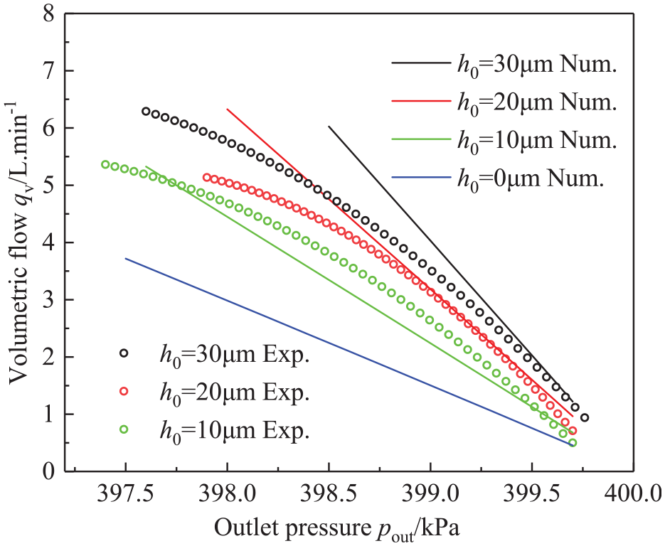
The variation of volumetric flow with outlet pressure at different initial clearance.
Fluid-structure coupling characteristics with back pressure
A scheme for adapting the diaphragm throttle to higher inlet pressure is proposed by introducing pressurized gas into the diaphragm back chamber, and partial throttling gas pressure is balanced by back pressure p3 to avoid excessive diaphragm deformation under high inlet pressure. Figure 12 presents the change law of the outlet pressure p2 and volumetric flow qv of the diaphragm-type restrictor during the process of increasing and decreasing the back pressure p3 when inlet pressure p1 = 0.4 MPa and initial clearance h0 = 0 μm. The elastic diaphragm is close to the end face of the nozzle under the back pressure p3 = 0.4 MPa, that is the throttle clearance is 0, and both the outlet pressure and gas volumetric flow are 0. The gradually reduced negative diaphragm deformation increases the throttle clearance as the back pressure decreases, at which time the outlet pressure and gas flow increase slightly. When the back pressure p3 decreases to a certain threshold pressure, both the outlet pressure and volumetric flow will surge, in which the gas flow may even reach a high peak value. This is because the increasing of outlet pressure will cause positive diaphragm deformation and increase throttle clearance remarkably, while the increasing of throttle clearance will lead to the increasing of outlet pressure. The result of this interaction is that the outlet pressure increases rapidly close to the inlet pressure. Conversely, as the back pressure gradually increases from 0, both outlet pressure and volumetric flow change little until a buck threshold pressure and then decrease suddenly and rapidly. The boost threshold pressure, which is generally 0.1–0.15 MPa, is significantly lower than the buck threshold pressure and is not sensitive to the diaphragm thickness. The buck threshold pressure is very sensitive to the diaphragm thickness, for example, when t = 0.2 and 0.6 mm, the values of which are close to 0.4 and 0.3 MPa, respectively. With the increases of diaphragm thickness, the sudden change of outlet pressure and volumetric flow will be alleviated, and the slope of output characteristic curve of the diaphragm-type restrictor will decrease gradually. It is obvious that diaphragm thickness of the diaphragm-type restrictor with back pressure should not be too small. To avoid fluctuations of downstream bearing or seal pressure, the back chamber pressure should be increased gradually from 0 and avoid decreasing from large value. Hence, the diaphragm thickness can be selected as 0.4–0.8 mm. When t = 0.4, 0.6, and 0.8 mm, the back pressure p3 are 0.3–0.35, 0.25–0.3, and 0.05–0.1 MPa, respectively.
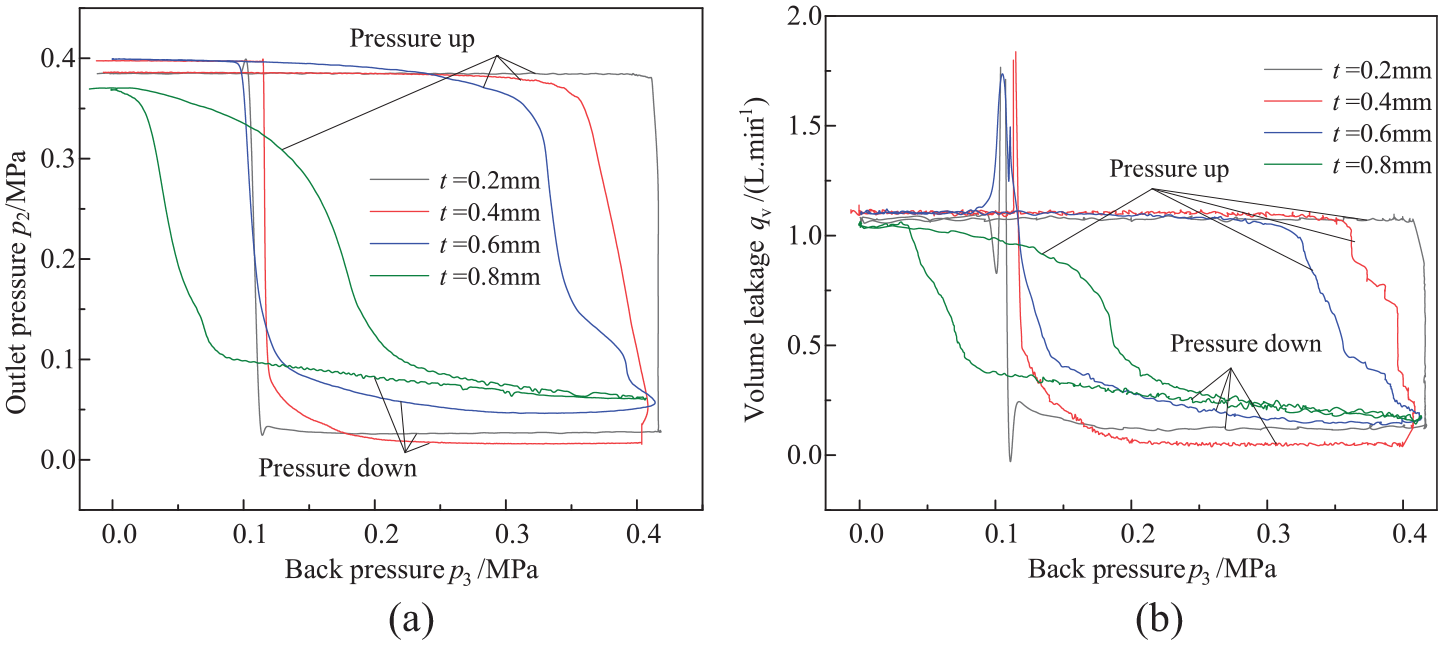
Effect of back pressure on output characteristics at different diaphragm thickness: (a) outlet pressure and (b) volumetric flow.
Figure 13 depicts the measured and calculated values of the outlet pressure varying with the initial clearance under different diaphragm thickness when p3 = 0.1 MPa and the volumetric flow is stable at (1 ± 0.1) L/min. The outlet pressure increases slowly with the increases of initial clearance, and the calculated outlet pressure is higher when the initial clearance is small, while the measured and calculated values agree well with each other when h0 > 15 μm. Considering that the initial clearance of a diaphragm-type restrictor is generally more than 20 μm, the fluid-structure coupling model of the diaphragm-type restrictor with back pressure established in this paper has high prediction accuracy for outlet pressure.

Outlet pressure at different initial clearance and diaphragm thickness when p3 = 0.1 MPa.
Conclusion
In this paper, a fluid-structure coupling numerical model for the diaphragm-type restrictor is established, the deformation of elastic diaphragm is predicted by using small deflection bending differential equation, and the gas flow characteristics on throttle clearance are predicted by using one-dimensional Reynolds equation considering outlet pressure blocking boundary. The correctness of the established numerical model is verified by comparing the measured and calculated values of diaphragm deformation, outlet pressure and volumetric flow under different conditions.
The diaphragm thickness has a significant influence on the diaphragm deformation, outlet pressure and gas volumetric flow. To avoid excessive diaphragm deformation and ensure proper sensitivity of outlet pressure and gas flow, the diaphragm thickness should be 0.6–0.8 mm.
Initial clearance has little effect on diaphragm deformation, but significant effect on outlet pressure and gas volumetric flow. Considering the stability and appropriate sensitivity of outlet pressure and gas flow, initial throttle clearance can be selected as 20–35 μm.
A diaphragm-type restrictor can be adapted to higher inlet pressure by introducing back pressure. However, it should be noted that the back pressure can only be adjusted in a gradually increasing but not decreasing manner, and the value should avoid sudden changes in the output characteristics. The appropriate back pressure value depends on the diaphragm thickness.
Footnotes
Appendix
Handling Editor: Chenhui Liang
Declaration of conflicting interests
The author(s) declared no potential conflicts of interest with respect to the research, authorship, and/or publication of this article.
Funding
The author(s) disclosed receipt of the following financial support for the research, authorship, and/or publication of this article: This research was supported by the National Natural Science Foundation of China (52075491, 51975528, 51975527), Zhejiang Provincial Natural Science Foundation of China (LGG21E050018) and Scientific Research Fund of Zhejiang Provincial Education Department (Y202147507).