
Abstract
Many studies have shown that bionic forms reduce drag through the control fluid medium. In this study, the evenly aligned pits of the whirligig beetle (Gyrinidae Latreille) notum were selected as the bionic form to be studied. They were used in centrifugal compressor impellers, called bionic centrifugal compressors, and the flow characteristics were simulated and compared to the prototype compressor. The simulation results show that compared to the prototype compressor, the pressure drag of bionic centrifugal compressors was reduced dramatically, while the pressure ratio was significantly improved. The pressure drag decreased by 19.24%, while the compression ratio increased by 9.8%. The bionic form of the blade delayed the boundary layer separation of the impeller suction surface, reducing the turbulent kinetic energy loss and improving internal air flow. The effect of drag reduction was shown to have a close relationship with the dimple size and bionic surface area; the greater the area, the better the drag reduction effect. However, there should exist an optimal bionic area, which could be determined by considering the flow velocity inside the impeller.
Keywords
Introduction
In a working air compressor, the high-speed rotating blades experience a great deal of resistance due to the viscosity of the compressed air, reducing the efficiency of the compressor. 1 The aerodynamic behavior of the centrifugal impeller is the key factor determining the compressor performance. 2 There are a number of traditional methods to improve the aerodynamic performance, such as optimization of the shape and structure of the centrifugal impeller.3–6 However, recently, more attention has been paid to biomimetic methods. For example, Sun et al. 7 designed a bionic axial fan blade with a nonsmooth leading edge, based on the long-eared owl wing, which demonstrates a remarkable reduction in flight noise. They found that the noise-reduction mechanism of this morphology is due to a reduction in the airfoil surface turbulent boundary layer pressure pulsation, which retards the rear airfoil shedding vortex separation, rectifying the flow around the subsequent airfoil and controlling the turbulence breakaway. Rong 8 investigated the drag reduction characteristics of airfoil blades with riblet structures in a centrifugal fan. Liu and Liu 9 developed a bionic airfoil based on the owl wing and investigated its aerodynamic performance and noise-reduction mechanism at a relatively low Reynolds number. The main means of movement of the above biological prototype methods is not rotation; thus, the application of such a bionic form to high-speed rotating air compressor impeller surfaces does not have good bionic motion similarity.
The whirligig beetle can rapidly swim in a spinning motion on the water surface and underwater. 10 Its minimum turning radius can be up to 3 mm, equivalent to 0.24 times its body length, and its swimming speed can be up to 0.62 m/s. 11 In particular, the rapid spin swim under water seems to be unaffected by resistance.12–14 Scanning electron microscopy (SEM) has shown that there are many evenly aligned pits on its notum, and studies have indicated that these pits can reduce the fluid–structure interface resistance.15–18 Thus, the pits of the whirligig beetle’s notum may play a role in reducing drag and improving swimming speed. Notably, the relative motion between the notum of the whirligig beetle and the surface (water) is similar to that of the compressor impeller and gas. Thus, the whirligig beetle was selected as a bionic prototype, and the distribution and scale of the morphological characteristics of its notum were analyzed using SEM. Based on the SEM results, two different bionic surfaces with different areas were designed and applied to certain types of centrifugal compressor. The flow characteristics of these, and of a prototype compressor, were determined using the computational fluid dynamics software CFX, and the mechanism of drag reduction was analyzed.
Bionic information processing
The whirligig beetle (Gyrinidae Latreille) belongs to the order Coleoptera and the family Dytiscidae. 19 The body is oval and flat, with a blue ink metallic luster (Figure 1(a)). They have a hard stiff exoskeleton, which does not bend easily and makes them look like hard shell boats. They swim rapidly in circles when they are frightened or mating. The whirligig beetles used in this study were collected from a river in Changchun city, in the northeast of China. They were killed using dry ice anesthesia processing, before metal spraying and observation by SEM. The SEM results are shown in Figure 1(b) and (c). There are many small pits on the notum of the beetle, arranged almost evenly spaced on both sides of the elytra (Figure 1(b)). The adjacent two lines of four pits present a parallelogram configuration, with spacing of about 120 μm, while the pit spacing is about 65 μm (see Figure 1(b)). The pits show a homogeneous spherical or ellipsoidal shape, with radii of about 20 μm, while the depth of the concave is about 8 μm (Figure 1(c)).
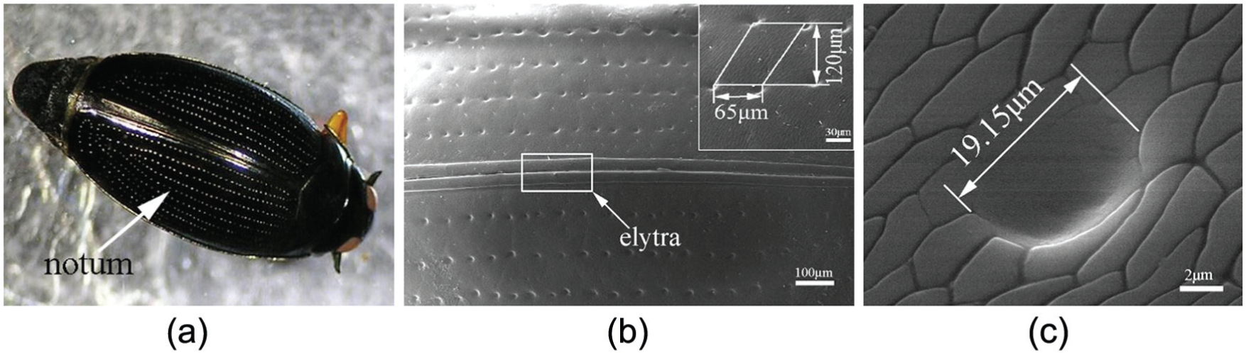
SEM of whirligig beetle: (a) whirligig beetle, (b) the pit arrangement on the notum, and (c) pit morphology and dimensions.
To consider the thickness and strength of the compressor impeller and investigate the effect of dimple sizes on the drag and compression ratios of the compressor, three bionic models with different dimple sizes are constructed. The details of the dimples are shown in Figure 2(a). The radius (R) and depth (D) of the models are shown in Table 1. The arrangement of these models presents a parallelogram configuration (see Figure 2(b)).
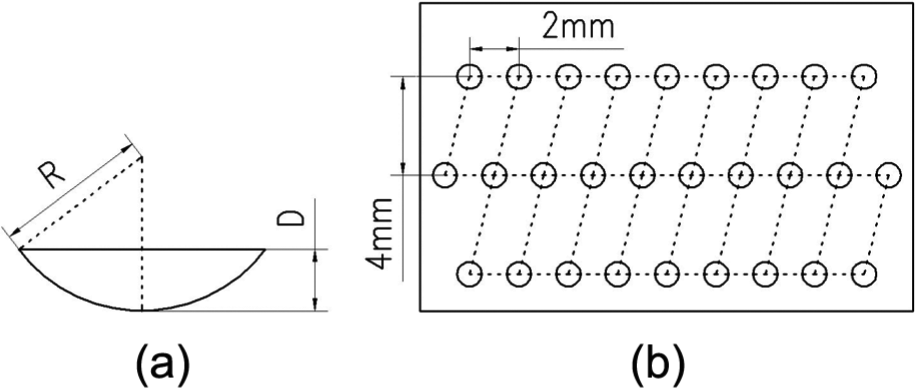
The bionic surface: (a) dimple detail and (b) arrangement of dimples.
The dimple sizes of three bionic models.

Prototype compressor model
Physical model
The impeller model was obtained from an actual impeller using a reverse engineering method, which was modified and perfected by Pro/E software. A simplified volute model was used, in which a single-stage compressor was constructed (Figure 3(a)). The radii of the inlet and outlet of the impeller were 162 and 207 mm, respectively, and the number of impeller blades was 13 (Figure 3(b)).

The simulation model of the compressor: (a) single-stage compressor and (b) the impeller.
The turbulent model and the boundary conditions
The flow in the centrifugal air compressor impeller was a typical turbulent flow, so the Shear Stress Transport (SST) model based on the k–ε model was used. The equations of the model are expressed as follows

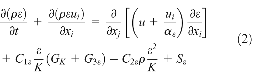
where k and ε are turbulent kinetic energy and dissipation rate, respectively; ρ is the density of air;
The ideal air was selected as the fluid medium during the simulation. The steady-state simulation of the fluid domain was set as follows. The rotation speed of the rotation field (near the impeller air) was −31,489 r/min; the rotation axis was Z and met the right hand rule. A nonslip heat insulation, smooth wall, was applied at the impeller surface. The import pressure of the static field P = 98,100 Pa, the temperature T = 293.15 K, and the mass flow of the export was 1 kg/s.
Discretization of the computation domain
The fluid domain uses a structural grid. The grid in the boundary layer plays an important role in determining the accuracy of the simulation results. Therefore, several layers of structural grid are inserted near the impeller wall.
To validate the simulated result invariance with the grid, a grid independence study is performed with prototype compressor model and bionic model 2 and the results are shown in Table 2.
Grid independence study.
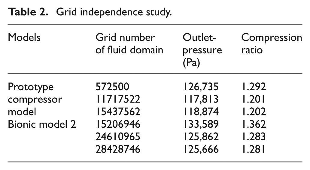
From Table 2, it can be seen that the outlet pressure and the compression ratio of prototype compressor model change slightly when the mesh density rises from 11717522 to 15437562, while for bionic model 2, these change slightly as the mesh density rises from 24610965 to 28428746. These changes indicate that there is little effect on the computation results when the grid number is 11717522 for prototype compressor model and 24610965 for bionic model 2. Using the same method, in considering the efficiency and accuracy of the calculation, the grid numbers for the fluid domain grid of bionic models 1 and 3 are 33532984 and 20211696, respectively (see Figure 4).

The grid diagram: (a) the grid of the fluid domain and (b) the grid detail of the impeller.
The simulation results of prototype compressor model
Although the viscosity and velocity of the fluid medium determine the boundary layer separation, they can also cause secondary flow, jet and wake,20,21 which cause a reduction in the total pressure of the compressor and affect the performance. Thus, an understanding of the flow velocity inside the compressor is very important. To achieve this, four intercept planes were selected on the impeller to analyze the flow characteristic (Figure 5(a)), whose location was determined by dimensionless number h, and h was calculated according to equation (3)


Impeller velocity vector: (a) the intercept planes of the impeller, (b) h = 0.9, (c) h = 0.8, (d) h = 0. 4, (e) h = 0.05, and (f) boundary layer separation and vortex.
where Z = 0.15, 0.13, 0.07, and 0.008 m, and H is the total axial height, 0.16 m. h = 0.9, 0.8, 0.4, 0.05 representing the air inlet, the top, the middle, and the bottom impeller, respectively.
Figure 5(b)–(e) represents the velocity vector diagrams at different planes. The color and length of the velocity vector reflect the speed of the air. Figure 5(b) shows that the air velocity at the entrance of the impeller presents an asymmetrical distribution. Figure 5(c) shows the velocity at the top impeller and it can be seen that the boundary layer became thicker on the suction side and separated from the impeller surface, with two small whirlpools present, similar to a vortex street (Figure 5(f)). This is due to the pressure difference between the pressure surface and the suction surface, with the air forced to flow from the former to the latter. Thus, the boundary layer becomes thicker and easily separated. Figure 5(d) and (e) shows the velocity vectors at the middle and bottom of the impeller, both of which are affected by the same flow characteristic of the top impeller at h = 0.8.
From this, it can be seen that the position h = 0.8 is very important in controlling the fluid medium to obtain good aerodynamic performance.
The bionic compressor model
Bionic model description
The above simulation results indicate that h = 0.8 is the crucial position and the air separation occurred at the suction side of the impeller. Thus, bionic pits were applied in the impeller from h = 0.8 and arranged on the suction side. The different dimple sizes and arrangement of the bionic pits of bionic models are shown in Figure 6.
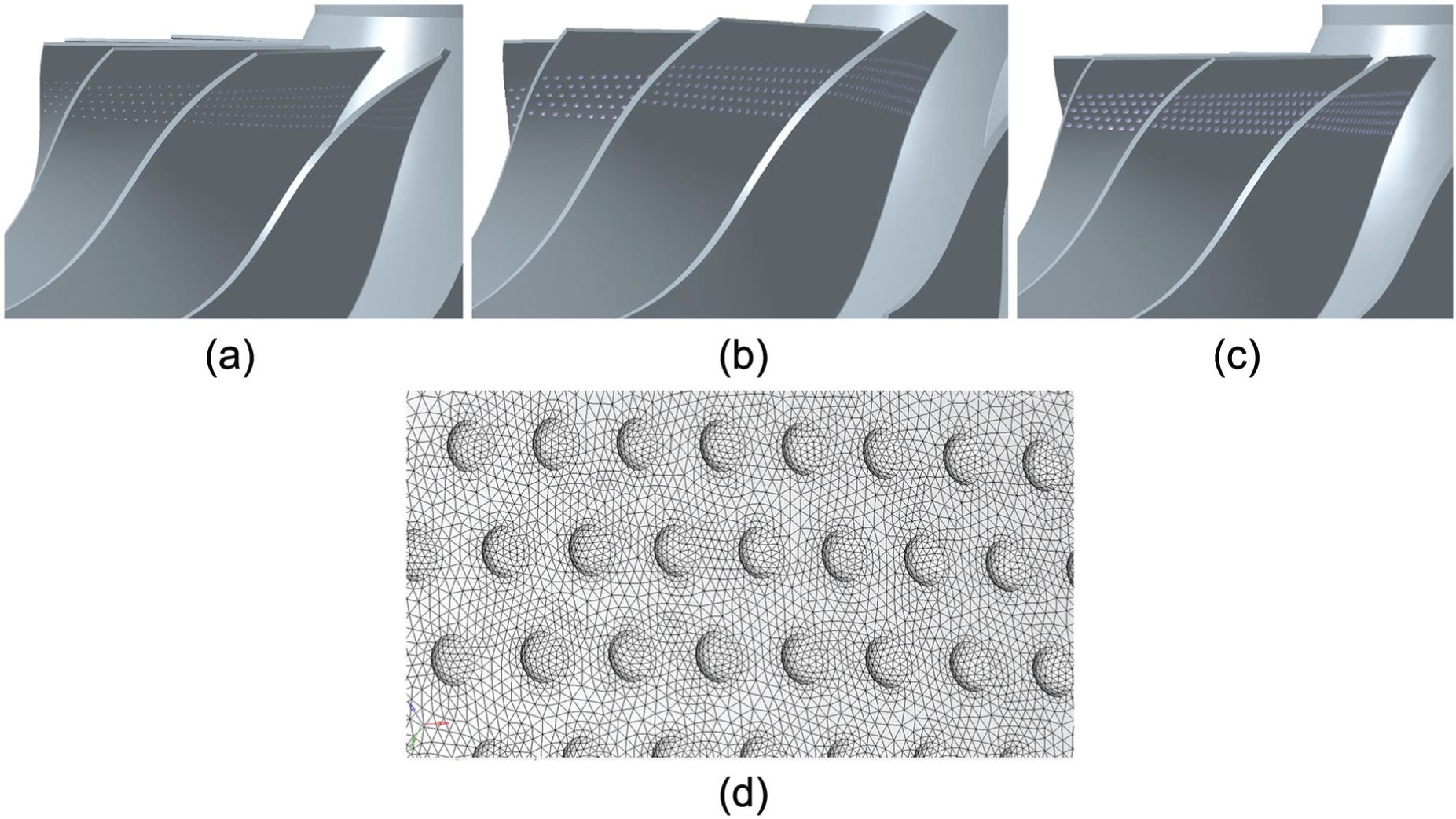
Bionic impellers and their grid: (a) bionic impeller model 1, (b) bionic impeller model 2, (c) bionic impeller model 3, and (d) grid detail of the bionic surface.
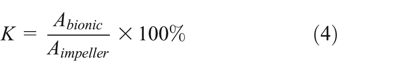
In addition, the two different bionic surfaces which would have affected the drag and compression ratio were also considered in this study (see Figure 7). The bionic surface was determined from the area ratio and calculated as follows

The impeller of bionic model 2 with different bionic surface areas: (a) impeller with K A = 16.7% and (b) impeller with K B = 45%.
where Abionic refers to the bionic pits’ layout area in the suction surface of the impeller and Aimpeller is the impeller surface area in the suction surface. After calculation, the area ratios of the bionic impeller A and impeller B were K A = 16.7% and K B = 45%, respectively.
The turbulent model, boundary conditions, and physical parameters were the same as that of the prototype compressor.
Compared to the size of the impeller, the scale of the bionic pits was very small, so the grid was refined on the bionic pit area and boundary grids were inserted into the surface of the impeller to accurately describe the characteristics of the bionic pit and improve the precision of the calculations. The grids of the bionic surface on the impeller are shown in Figure 6(d).
Results
The effect of dimple size on the result
Table 3 shows the drag and compression ratios of all of the bionic models. From Table 3, it can be seen that the pressure drag of the bionic models is reduced dramatically, but the viscous drag is increased slightly. As the pressure drag holds an absolute advantage in the total resistance, a reduction of the total drag is obtained. The compression ratios are increased compared to the prototype model by 5.91%, 6.83%, and 6.08%, respectively.
Drag and compression ratio of the compressor.

Table 3 indicates that the dimple size is related to the drag reduction and the compression ratio enhancement of the compressor. Bionic model 2, in which the dimple size dimensions are R = 1.25 mm and D = 0.5, has the best drag reduction, as the pressure drag decreases by 17.27%. In this condition, the compression ratio increases by 6.83%.
The effect of bionic surface area on the results
According to above simulation results, a bionic model 4 is built, based on bionic model 2. The difference between these models is that the bionic surface area of bionic model 4 is 45%. The simulation results are shown in Table 4. Pressured drag and viscous resistance are produced during centrifugal compressor rotation. The pressure drag of the bionic models significantly decreased, with reductions of up to 17.27% and 19.24%, respectively. The compression ratio of the bionic models increased by 6.82% and 9.8%.
Drag and compression ratio of the compressor.
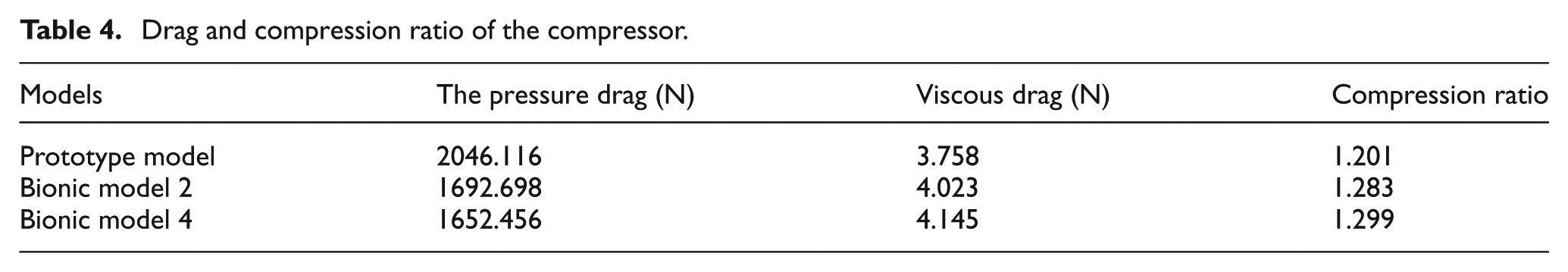
Figure 8 shows the pressure distributions of all the models. For the prototype air compressor, the pressure gradually increased along the direction of the air flow, from the inlet to the outlet of the impeller, with the existing negative pressure zone in the suction surface of the inlet (Figure 8(a)).
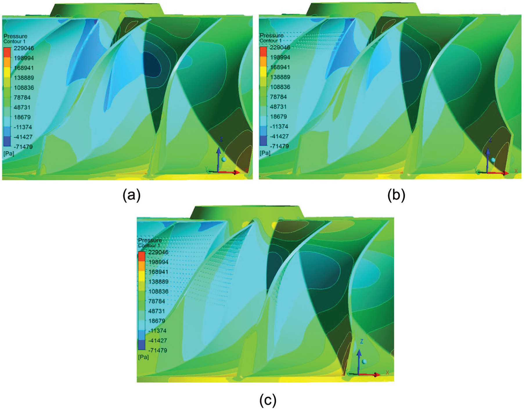
The pressure distributions of the models: (a) prototype model, (b) bionic model 2, and (c) bionic model 4.
Figure 8(b) and (c) shows the distributions of the bionic models. The trends of the distributions were the same as that of the prototype model. However, the negative pressure zone on the suction surface became smaller for bionic model 2 and did not exist for bionic model 4. Thus, the bionic surface improved air flow inside the air compressor.
Discussion
The above simulation results show that the bionic surface reduced drag and considerably improved the flow performance of the centrifugal compressor. The mechanism of drag reduction relied on the evenly arranged pits on the surface, organized together and applied at the critical position of the impeller, delaying the separation of the air (Figure 9(a) and (b)). Figures 5(f), 9(a) and (b) show the velocity vector on the suction surface for the three models at h = 0.8. They reflect the separation condition of the air flow.

The velocity on the suction surface at h = 0.8: (a) bionic model 2 and (b) bionic model 4.
There were obvious separation points on the suction surface of the impeller, with small whirlpools present similar to a vortex street, which were generated and then fell off regularly (Figures 5(f) and 9(a)). The difference between the prototype model and bionic model A was the separation position. Compared with the prototype model (Figure 5(a)), the boundary layer separation of bionic model A was significantly delayed (Figure 9(a)). For bionic model B (Figure 9(b)), the separation of the boundary layer was delayed further, and there were even small vortexes formed near the suction surface, which did not seem to fall off at all. The boundary layer delay indicates that the drag was reduced. In addition, the vortex generation, diffusion, and dissipation near the suction surface consumed large amounts of energy, leading to decreased efficiency of the compressor. The boundary layer separation delay also reduced the strength of the vortex, thus improving the flow performance of the centrifugal compressor.
The above analysis suggests that the small pits on the suction surface of the impeller achieved the drag reduction by delaying the boundary layer separation.
In addition, it was found that the drag reduction and pressure ratio increase effect were very closely related to the increase in bionic area. However, the increased bionic area reduced the flow velocity inside the impeller.
Table 5 shows the mean velocity at the four different intercept planes shown in Figure 5(a). The increased velocity rate, r, was calculated according to equation (5)

The mean velocity at different sections.
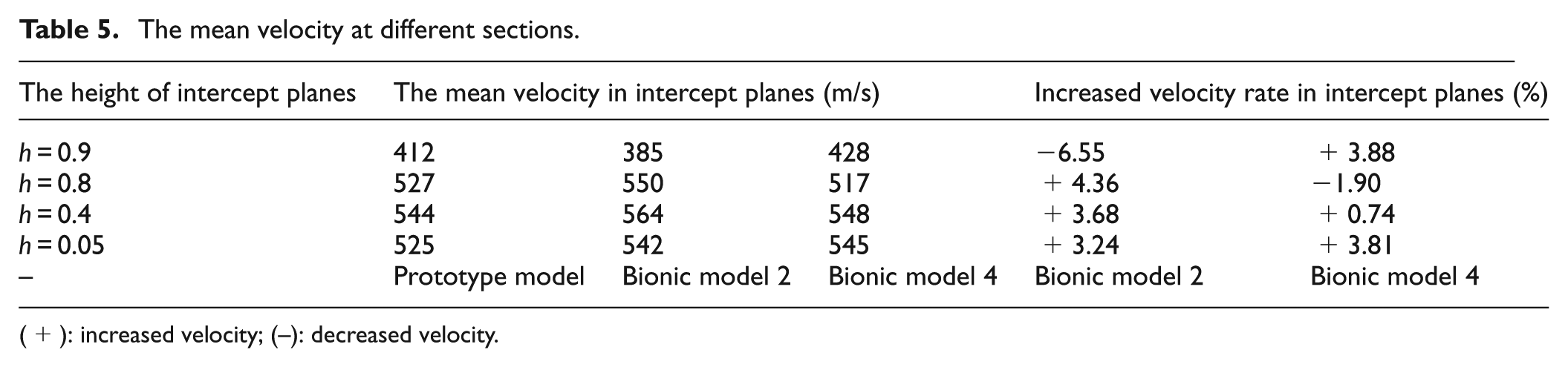
(+): increased velocity; (–): decreased velocity.
where vbionic model and vpototype model are the mean velocities of the bionic model and the prototype model, respectively.
Table 5 shows that when the small pits were arranged on the impeller, the mean velocity of the air increased at most positions for the bionic models. This is an ideal situation considering that it accelerated the air flow in the impeller. However, as the bionic area increased, the velocity did not noticeably increase, and even decreased at some positions compared with bionic model A, such as at h = 0.4 and h = 0.8. Thus, from the point of view of improved air flow velocity, for the bionic area bigger is not better. There should exist an optimal bionic area to improve the flow performance.
Conclusion
From the above simulation results and analysis, the following conclusions are obtained:
The pit formation based on the notum of the whirligig beetle was applied to the centrifugal compressor. This reduced the drag and increased the pressure ratio due to the delayed separation of the boundary layer.
Despite the drag reduction, the effect was improved by increasing the bionic surface area. However, there should exist an optimal area, determined by considering the flow velocity inside the impeller.
Footnotes
Academic Editor: Pietro Scandura
Declaration of conflicting interests
The authors declare that there is no conflict of interest regarding the publication of this article.
Funding
This study received grants from the National Natural Science Foundation of China (Grant No. 51475203), Major State Basic Research Development Program of China (Grant No. 2011CB013403), the high-tech industrialization demonstration projects of Jilin province (Grant No. 20140307030GX), and the Changchun special project of major scientific research (Grant No. 13KG33).