
Abstract
Two-stage mounting systems applied in ships are expected to be light in weight, compact in installation space, and efficient in vibration isolation performance at the same time, which largely increases the engineering complexity. In this paper, analytical models of a two-stage mounting system with flexible and rigid intermediate mass are proposed to compare the vibration isolation effectiveness (VIE) performance and the influences of system parameters with the rigid intermediate mass on VIE are introduced. Based on the analysis results, an integrated adjustable two-stage mounting module is designed. Compared to the traditional floating raft mounting system with flexible intermediate mass, this two-stage mounting module can be arranged in a more compact structure space with greatly reduced size and weight. Furthermore, a novel modular mounting system prototype is proposed and manufactured based on several two-stage mounting modules and real-time behavior monitoring and controlling subsystem. The testing results verify the compatibility of the module design and the behavior monitoring and controlling system. The modular mounting system also exhibits excellent VIE performance combined with the advantage of compact intermediate mass size, lightweight, and automatic behavior monitoring and controlling.
Keywords
Introduction
Vibration and noise generated by the operation of power machinery have many adverse effects on the ship. Vibration-induced structure noise spreading to the cabin through the hull structure will lead to the deterioration of the crews’ working and living environment. The hull structure and equipment produce fatigue damage easily when subjected to long-term alternating load. In addition, vibration will interfere with the operation of precise instruments and equipment such as sonar and thus undermines their performance. What’s more, the acoustic stealth performance will inevitably deteriorate as the vibration-induced radiation noise increases.1–3
The machinery mounting system is one of the most important vibration and noise attenuation technologies. 4 In recent years, techniques and applications that decrease vibration and noise levels are warmly pursued due to the requirements of not only the enhancement of human comfort and well-being in the cabin but also lower acoustic radiation for most ocean survey and naval vessels. 5 To meet the stringent requirements of reducing vibration and noise on ships, new efficient mounting technologies are urgently needed.
So far, various machinery mounting systems are applied including simple mounting and two-stage mounting systems (floating raft mounting system and whole cabin floating raft mounting system). The two-stage mounting system has drawn increasing attention due to better vibration isolation effectiveness (VIE) performance. It has been reported that the attenuation rate of the high-frequency force transmission rate of a two-stage mounting system is about 24 dB per octave under ideal conditions, which requires the rigidity of intermediate mass to be infinite.6–10 A two-stage mounting system was first applied to a submarine diesel generator set by West Germany in the 1960s. Based on a two-stage mounting system, a floating mounting system, a special vibration isolation structure was developed for ships and submarines. By applying floating mounting systems, the vibration of hosts and auxiliary machines can be isolated, and the structural noise of ships and submarines can be reduced effectively. Furthermore, such a system can prevent the equipment to be isolated from being damaged when subject to strong external disturbances or extreme conditions such as severe vessel motion or severe fault. 11 When extended in size and applied to the whole cabin, floating raft mounting develops into the whole-cabin floating raft mounting system. It has been reported that the application of floating raft size can reach up to 10 × 20 m. In the 1990s, the patent of vibration isolation using floating raft applied by General Electric Boat Company in 1988 12 was implemented on the “Seawolf” and “Virginia” class nuclear submarines, where all the power equipment in the power section is mounted on a large floating raft. 13 The main power system of the British Navy’s “Sensitive” class nuclear submarine also employed a highly integrated, large-scale, whole cabin floating raft. 14
With the trend of boat design to be larger in scale, the structural stiffness will be inevitably undermined. Also, more unexpected potential factors affecting the VIE performance will be brought about, such as more modal frequency of the floating raft itself and more excitation available, and more components likely to be affected adversely with more complex equipment and machines to be isolated.15,16 However, constrained by the overall space, general layout, and center of gravity of the ship, the development trend of the two-stage mounting system is to be light in weight while maintaining efficient vibration isolation performance. Therefore, studying lightweight mounting systems is of great significance and urgency.
Relatively few authors have been involved in the study of lightweight mounting systems. Cui and Zhu 17 adopted the topological optimization method to optimize the structure of the intermedia raft. The simulation showed that the optimized raft structure maintains the desired performance when the weight is greatly reduced. Qin et al. 18 explored the application of arbitrary Poisson’s ratio and zero Poisson’s ratio metamaterials in ship raft structures to achieve both lightweight design and vibration reduction. Zhang et al. 19 developed a new cradle truss raft structure, the VIE performance of the truss raft is much better than the conventional raft structure with equivalent mass which showed that a truss-type floating raft has broad application prospects in reducing the weight of the mounting system.
In this paper, the VIE performance comparison models of two-sage mounting with flexible and rigid intermediate mass are established. The influences of system parameters on VIE performance are analyzed quantitatively. A novel integrated adjustable two-stage mounting module comprising of rigid intermediate mass, air spring hard material isolator, and behavior controlling system is then designed based on theoretical analysis. A novel modular mounting system consisting of several two-stage mounting modules and real-time behavior monitoring and controlling subsystem is proposed, which can be arranged in a compact structure space and greatly reduce the total size and weight of the mounting device compared with traditional floating raft mounting system with flexible intermediate mass. The system has an adjustable range of bearing capacity and exhibits excellent vibration attenuation and behavior controlling performance at the same time. The novel modular mounting system is applied on a piece of ship mechanical power equipment. VIE performance and behavior monitoring and controlling experiments are carried out to verify its superiority. Experimental results show that the VIE performance far exceeds the index requested even with the least amount of 15% of the total mass of mechanical equipment, which is about 50% weight reduction compared with the two-stage mounting system with flexible intermediate mass. The system also presents good behavior control accuracy which is within 2 mm.
Analytical models and dynamic analysis of two-stage mounting system
Analytical models
The two-stage mounting system exhibits better VIE performance than a simple one-stage mounting system, especially at high frequency due to additional intermediate mass and lower mounts installed. The structure design of intermediate mass for a two-stage mounting system is the key to realizing efficient vibration isolation. 20 The intermediate mass generally adopts two structural forms: one is the overall frame structure, and the other is the distributed rigid mass block structure.
To compare and analyze the VIE performance of two-stage mounting systems with different intermediate mass structure forms, two vibration transmission models are established, and the mobility matrix method is used to derive the VIE calculation formulas. The overall frame structure intermediate mass is a platform composed of plates, beams, etc. The structural stiffness is relatively weak, and there are many medium and high-frequency vibration modes. To simulate the distribution characteristics of its mass and elasticity, 21 the overall frame structure intermediate mass is simulated as a simply supported beam (S-S beam) as shown in Figure 1(a); however, the distributed rigid intermediate mass is a relatively small size of metal blocks with large stiffness, which can be regarded as a rigid body of uniform mass distribution as shown in Figure 1(b). The source is represented directly by a force excitation. The models are relatively simplified because the emphasis of this paper is to compare VIE performances of two-stage mounting systems with different forms of intermediate mass. In practical engineering applications, vertical vibration energy is more significant than any other direction. Therefore, in the calculation of VIE, only the force along the vertical direction is considered for simplicity as well.

Simplified models of two-stage mounting system: (a) intermediate mass: S-S beam and (b) intermediate mass: rigid body.
The four elements in the impedance matrix of the mount


Where
The motion equation of the upper mount in the two-stage mounting system as is shown in Figure 1 can be expressed as

The motion equation of the intermediate mass is

Where
The motion equation of the lower mount can be easily obtained as

The receiver’s velocity can be expressed as

Combine equations (1)–(6) to obtain the receiver’s velocity of the two-stage mounting system as shown below

The most frequently used indicator to measure VIE performance of the mounting system is the velocity transmissibility. Transmissibility may be defined as the ratio of the velocity amplitude at the receiver to the velocity amplitude on the source side of the mount as shown below

Analysis of transmission characteristics comparison
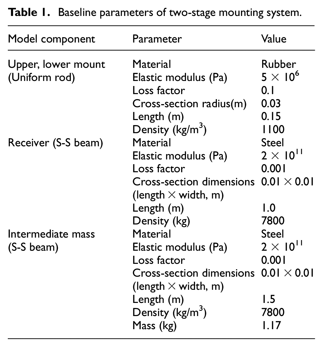
A specific numerical example is presented to compare the VIE difference with different forms of intermediate mass when their amounts of them are equivalent. The baseline parameters of the two-stage mounting system are shown in Table 1.
Baseline parameters of two-stage mounting system.
The length of the beam increases from 1.0 to 1.5 m and 2.0 m, and they are respectively replaced by a rigid mass block whose amount is equivalent to the 1.0, 1.5,and 2.0 m length beam mass. The VIE of two systems with different forms of intermediate mass are calculated respectively, and the results are shown in Figure 2.

VIE comparison between S-S beam intermediate mass mounting system and rigid intermediate mass mounting system with different amounts of mass.
The amount of the rigid mass block is further reduced, making it equal to 1/10, 1/100 amount of 1.5 m length S-S beam mass. The VIE performance is shown in Figure 3.

VIE comparison of systems with different forms and amounts of intermediate mass.
It can be seen from the two figures that the system with rigid intermediate mass obtains much better VIE than the system with flexible intermediate mass if with an equivalent amount of intermediate mass in a broad frequency band. Figure 3 illustrates that when the amount of rigid intermediate mass is further reduced to 1/10 amount of 1.5 m length S-S beam mass, the VIE of the system with rigid intermediate mass generally equals that of the system with flexible intermediate mass. The superior VIE performance of the two-stage mounting system is predicated upon the additional mass remaining rigid at the frequencies of interest: 10 Hz–8 kHz. The usual overall frame structure intermediate mass design, which exhibits great flexibility and modal behavior at acoustic frequencies does not act as rigid masses at these frequencies, and the advantages of a two-stage mounting system are lost. Therefore, it can be surely concluded that better VIE and a saving in weight will be obtained by replacing the overall frame structure intermediate mass with compact rigid masses.
Influence of system design parameters on VIE
To clarify the influences of the two-stage mounting system with rigid intermediate mass design parameters on VIE, a quantitative analysis of different system design parameters is carried out.
Influence of the amount of rigid intermediate mass
The VIE of the system is calculated at the frequencies of interest according to VIE calculation formulas derived in section 2.1. Figure 4 shows the curves of calculated results along the frequency axis, each with a different amount of rigid intermediate mass:50, 100, 150, and 200 kg. From Figure 4, it can be observed that an increase in the amount of rigid intermediate mass will dramatically improve the VIE performance of the system. However, it is also interesting to observe that the incremental VIE become smaller with equivalent mass increment on rigid intermediate mass. There exists a “marginal effect” on the VIE performance of the two-stage mounting system with rigid intermediate mass.
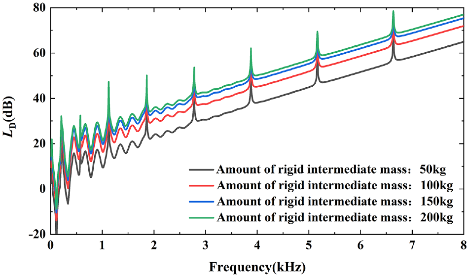
VIE of system with different amounts of rigid intermediate mass.
Influence of elastic modulus of mount’s material
The VIE performance of the system with the elastic modulus of upper and lower mounts’ material changing from 5 to 40 MPa are shown respectively in Figures 5 and 6.
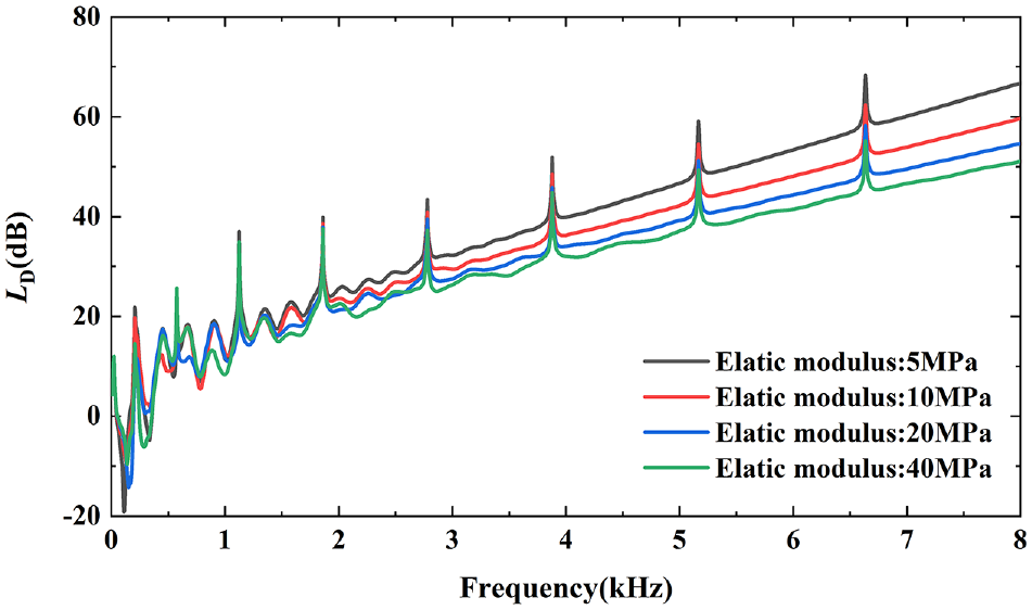
VIE of system with a different elastic modulus of upper mount’s material.

VIE of system with a different elastic modulus of lower mount’s material.
How to choose proper upper and lower mounts is the primary question when designing a two-stage mounting system. Stiffness is the most basic and important parameter of mounts. The stiffness of the mount is determined by the elastic modulus of its material made of. Two different stiffness configurations of upper and lower mounts are adopted: (1) upper mount: 5 MPa, lower mount: 40 MPa; (2) upper mount: 40 MPa, lower mount: 5 MPa. The VIE performance of the system with different stiffness configurations is shown in Figure 7.

VIE of system with different stiffness configuration.
It can be concluded that the mount with a lower elastic modulus achieves better VIE performance and the relationship between the magnitude of the improvement on VIE and the magnitude of the reduction of the mount’s stiffness is the same. Figure 7 shows that it is better to place mounts with larger stiffness on the upper layer when upper and lower mounts are determined.
Influence of damping of mount’s material
Figures 8 and 9 show the influence of damping of mounts’ material on VIE. The damping is determined by the magnitude of the loss factor. The loss factor of upper and lower mount change from 0.05 to 0.20 according to material frequently used respectively. It can be observed that the VIE of the system is greatly improved by increasing the magnitude of damping, especially in the high-frequency domain, and the higher, the more apparent. Therefore, the application of high damping rubber or constrained damping layer attached to mounts used in the mounting system is of great use in improving VIE of the system.

VIE of system with different loss factors of upper mount’s material.
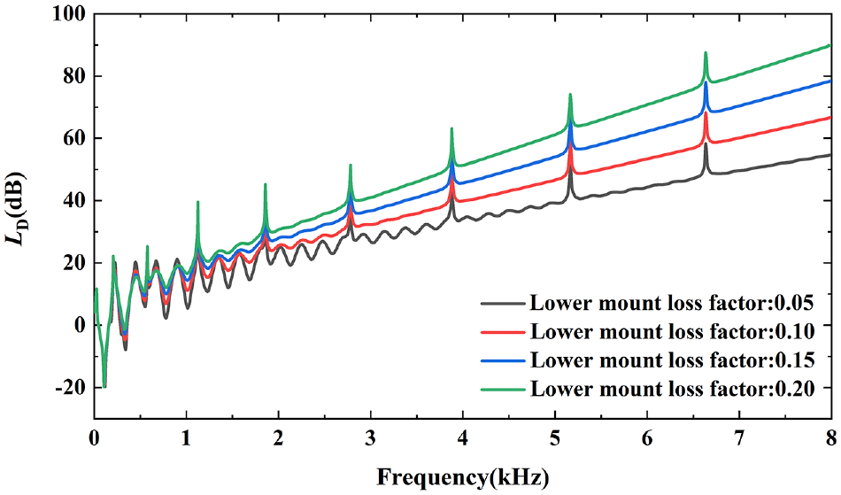
VIE of system with different loss factors of upper mount’s material.
Design of novel modular mounting system
Structure of integrated, adjustable two-stage mounting module
Based on the systematic theoretical analysis of the two-stage mounting system above, a kind of integrated and adjustable two-stage mounting module is designed. The structural schematic of the module is shown in Figure 10.

Schematic of the integrated adjustable two-stage mounting module.
As is shown in Figure 10, the air spring with smaller stiffness is installed between the receiver and rigid intermediate mass and the upper mount made of hard elastic rubber material is installed between rigid intermediate mass, and mechanical equipment to be isolated. The stiffness of the upper mount is larger than that of the air spring. The rigid intermediate mass is made of compact mental blocks with great rigidity. The rigid intermediate mass is designed to be adjustable. Additional small mass blocks and dynamic vibration absorbers can be integrated into the intermediate mass to improve VIE performance if needed so that a lot of installation space will be saved. The air spring is connected to the pressure sensor, inflating the solenoid valve, and deflating the solenoid valve through the air tube. The inflation and deflation control unit consisting of a controller, placement sensors, pressure sensor, inflating the solenoid valve, and deflating the solenoid valve is integrated into a rigid intermediate mass as well. The inflating solenoid valve is connected to a compressed air source.
The main features of the design are as followed below:
(1) The height of the module is monitored in real-time and precisely controlled, which is the basic requirement when applied to isolate mechanical equipment’s vibration. When the load exerted on the module or the number of intermediate mass changes, the controller sends the air spring pressure adjustment command to the solenoid valve to precisely control the height of the two-stage module according to the signals collected from the displacement sensors and pressure sensor. The working principle of the module’s height monitoring and controlling system is shown in Figure 11.

Working principle of module’s height monitoring and controlling system.
(2) The inherent frequency of the air spring remains substantially unchanged due to the adjustable pressure parameters. For instance, the pressure inside the air spring increases when additional intermediate mass is installed on the module and the increase in the stiffness of the air spring will be followed, so that the inherent frequency of the air spring remains relatively stable which is necessary for maintaining efficient VIE performance.
(3) The amount of intermediate mass is adjustable by installing small mass blocks and the rigidity of intermediate mass is always guaranteed at the same time. The VIE performance can be adjusted within a certain range conveniently by increasing or decreasing the number of mass blocks according to practical needs.
(4) Active or passive dynamic vibration absorbers can be integrated into the rigid intermediate mass to suppress the vibration of mechanical equipment at a particular frequency. Compared with installing DVAs directly on mechanical equipment, installing DVAs on rigid intermediate mass exhibits better performance in saving installation space, and DVAs installed also increase the amount of intermediate mass which is beneficial to improve VIE performance as well.
The two-stage mounting module is highly integrated and compact, and the height of the mounting device is precisely controllable. It is convenient to adjust the intermediate mass by installing additional small mass blocks or DVAs when VIE performance does not meet the requirements and meanwhile maintaining that the key parameters of the mounting system such as deformation and inherent frequency of mounts remain stable. The module with adjustable design can be easily optimized through a series of experiments and then applied to deal with vibration isolation problems of mechanical equipment.
Layout design of the novel modular mounting system
The novel modular mounting system based on the integrated and adjustable two-stage mounting modules designed in Section 3.1 is proposed and applied to deal with the vibration isolation problem of a piece of large-scale and high-power mechanical equipment with stringent requirements on the total amount and installation space of the mounting device. Specific dimensional parameters and type of mounts used in the module are determined by the mechanical equipment to be isolated. Rubber mounts made of polyurethane are applied as the upper mounts. Ten modules are used to evenly support the mechanical equipment according to certain principles as is shown in Figure 12.

Schematics of modular mounting system for a piece of large-scale and high-power mechanical equipment.
The total amount of modular mounting system can be adjusted in the range of 15%–25% amount of mechanical equipment, which is about a 50% reduction if the amount of intermediate mass is 15% of the equipment compared with applying a conventional two-stage mounting system with flexible intermediate mass. And the size of the mounting device is decreasing dramatically so that it can be installed easily. The design is light in weight, compact in installation space, and expected to be efficient in VIE performance at the same time.
Design of behavior monitoring and controlling system
When the novel modular mounting system applied is subjected to strong disturbances such as ship inclination of a large angle, considerable overturning torque or air leakage of air spring, etc. The system will deviate from the equilibrium behavior and endanger the operation safety of the equipment. The system will control the behavior of the mounting device precisely within an acceptable range by adjusting the air spring’s pressure automatically in real-time. And the distribution of air springs’ load is maintained as even as possible when the control process is activated.
The behavior monitoring and controlling system aare composed of the inflation and deflation control units integrated into the module, compressed air source and control box of the whole system as is shown in Figure 13.

Schematics of behavior detection and control system.
The control box will automatically program the optimal controlling path and deliver an adjustment command signal to the inflation and deflation unit to execute inflation or deflation operation on each module independently when the system deviates from equilibrium behavior according to data collected by displacement sensors and pressure sensors. The working principle of behavior monitoring and controlling system is shown in Figure 14.

Flow chart of behavior control of the mounting device.
Experimental verification
A series of experiments were conducted on a large-scale and high-power mechanical equipment prototype applying the novel modular mounting system as is shown in Figure 15 to verify its superior performance.

Prototype of the novel modular mounting device.
VIE testing
The VIE of the novel modular mounting system is measured by twenty accelerometers, 10 at the mechanical equipment and 10 at the receiver nearby each module’s air spring installed on the bottom. Figure 16 shows the VIE tested result in the frequency range 50 Hz–4 kHz. The VIE performance expressed by total acceleration level attenuation (re: 10E-6 m/s2) far exceeded the index requested even with the least amount of rigid intermediate mass which is about 15% of the mechanical equipment. The system exhibits better VIE performance in the high-frequency domain because there are no wave effects that are often observed in other mounting systems and are undesirable. Theoretical analysis results indicate that there exists a “marginal effect” on VIE performance of the two-stage mounting system with rigid intermediate mass. This phenomenon is confirmed by three groups of experiments as is shown in Figure 16. The amount of intermediate mass applied ranges from 15% to 25% with an equivalent increment of the mechanical equipment by adjusting the number of small mass blocks. Compared with the traditional floating raft mounting system, the novel modular mounting system can achieve almost the same VIE performance with a weight reduction of 50%.
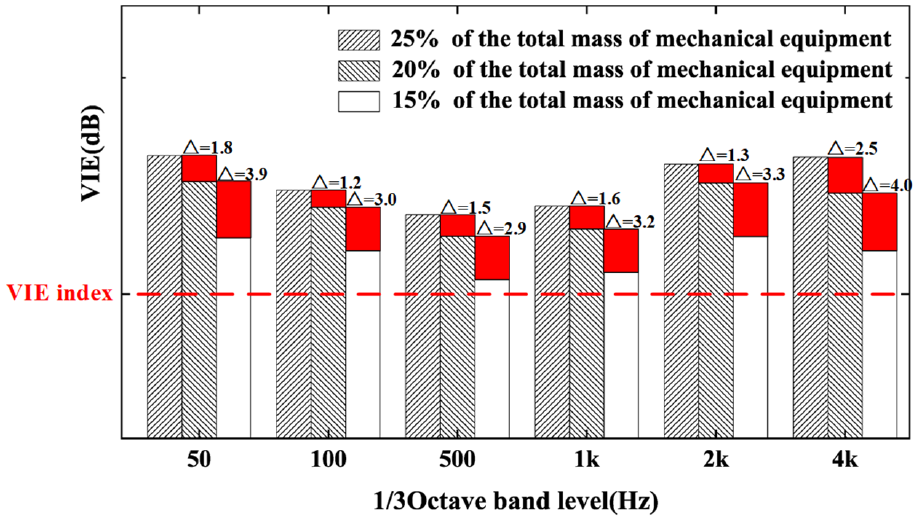
Tested VIE performance of the prototype.
Therefore, satisfactory VIE performance will be obtained at less amount cost of intermediate mass by applying the novel modular mounting system with rigid intermediate mass design, compared with the conventional massive overall frame structure. Because the limited amount increase on intermediate mass does not increase its rigidity dramatically, thus the VIE performance will not be greatly improved either. On the contrary, it will reduce the load capacity of the ship which is more important for most ships. Light-weight design of intermediate mass highly coincides with the practical engineering requirement so that the modular mounting system exhibits excellent application prospects.
Behavior monitoring and controlling system testing
Figure 17 shows the control process in which the novel modular mounting system is subject to external disturbance. The behavior monitoring and controlling system will automatically program the optimal controlling path immediately when the mounting system deviates from the equilibrium behavior. In the beginning, the disturbance occurred, and then followed with that the height of each module deviated from the acceptable range to the unacceptable one. The system started the control process through deflation operation or inflation operation. In a short time, the height of each module converged within 2.0 mm which meets the behavior control precision request, and the equilibrium behavior is recovered. The behavior monitoring and controlling system are verified to be effective through the experiments mentioned above.
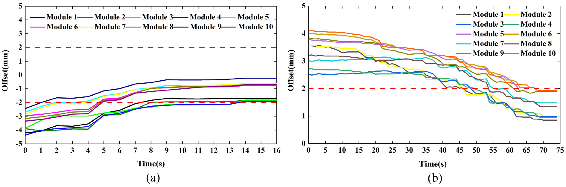
The offsets of mounting device during behavior control process: (a) inflating process and (b) deflating process.
Conclusion
The two-stage mounting system which effectively attenuates the vibration of the ship cabin and acoustic radiation is expected to be as light in weight as possible. In this work, a kind of specially designed two-stage module is proposed after a systematic theoretical analysis of the two-stage mounting system. A novel modular mounting system based on specially designed two-stage mounting modules is presented. The experimental results of the application of the novel modular mounting system verify the applicability of the module design, behavior monitoring and controlling system. The experimental results also show that the modular mounting system exhibits excellent VIE performance combined with the advantage of compact intermediate mass size, lightweight, automatic behavior monitoring, and controlling. The system has been applied to a piece of large-scale mechanical equipment and operates smoothly.
In the next paper, the modules integrated with active or passive dynamic vibration absorbers to suppress the low-frequency line spectrum produced by the rotary reciprocating mechanism during operation, which is of great significance and urgency in improving the naval vessels’ acoustic stealth, will be discussed.
Footnotes
Handling Editor: Chenhui Liang
Declaration of conflicting interests
The author(s) declared no potential conflicts of interest with respect to the research, authorship, and/or publication of this article.
Funding
The author(s) disclosed receipt of the following financial support for the research, authorship, and/or publication of this article: The authors would like to acknowledge support from the National Defence Key Laboratory of Fund Project of China (No. 6142204190604).
Availability of data
The data that support the findings of this study are available from the corresponding author upon reasonable request.