
Abstract
A dynamic model of an asymmetric system is developed with limiter under heave conditions to explore the impact characteristics of a marine rotating machinery coupled airbag-floating raft-limiter systems. The steady-state response of the system is numerically solved using the Runge-Kutta theory. Nonlinear dynamic analysis methods, including energy trajectories and time-averaged energy diagrams, have been introduced to examine the influence of rotor speed, heaving amplitude, limiter clearance, and contact stiffness on the dynamic characteristics of the system. The results show that the amplitude of the heave increases, the system collides with the limiter, resulting in a significant reduction in amplitude. Meanwhile, the dynamic behavior of system transitions from quasi-periodic motion to chaotic state. After the impact, the energy of the system begins to concentrate in the region of impact, and the higher the time-averaged energy value, the more severe the impact of the system. The method proposed in this paper can provides an optimization scheme and theoretical reference for the impact problem of this system.
Introduction
In rough seas, ships undergo dynamic movements such as heaving, pitching, and rolling. 1 The ship hull experiences lateral displacement in response to wave undulations, with the frequency of this displacement influenced by the frequency of the waves. While the heaving frequency is lower than the rotating frequency of the mechanical systems within a marine pontoon raft-airbag assembly, the inertial forces produced during heaving significantly impact the normal functioning of these mechanical systems. Therefore, the study of the dynamic properties of the floating raft-airbag system under heave conditions can offer more precise theoretical insights for refining the parameters of the floating raft-airbag.
The floating raft-airbag isolation system serves as a crucial mechanism for mitigating and isolating vibrations, with wide-ranging applications in the maritime industry, offshore platforms, and various structures.2,3 This system effectively reduces the impact of external forces such as heave, thereby enhancing ship stability and minimizing the risk of structural fatigue and damage. Eminent scholars have conducted extensive investigations into the dynamic behavior of the floating raft-airbag vibration isolation system. Their research indicates that this system exhibits complex dynamic behaviors similar to those of rotating mechanical systems, including phenomena such as single-cycle, multi-cycle, quasi-periodic, and chaotic dynamics.4–6 For example, Lv et al. improved the low-frequency isolation effect by incorporating an airbag isolator into a floating raft isolation device. 7 This determination of optimal airbag pressure not only maintained raft stability but also provided theoretical support for vibration control and system optimization.
A limiter acts as a mechanism engineered to regulate and demarcate the allowable operational boundaries within which machinery or equipment can equipment. 8 Its primary objective is to stop or redirect the movement of the machinery upon reaching a pre-defined position, thereby averting damage or accidents that might arise from surpassing the motion range. In the domain of marine rotating machinery, recent studies have demonstrated that opting for a smaller limiter gap and combining it with suitable stiffness can prove advantageous in reducing system resonance.9,10 Ship operations in demanding sea conditions pose a substantial challenge to the rotational machinery of mechanical systems on ships. The utilization of limiters boosts the speed and efficiency of ship rotational machinery. Nevertheless, incorrect design or installation of limiters can lead to equipment damage or malfunction. Hence, undertaking parameter optimization and design research for limiters is indispensable.
Contact impact is a prevalent mechanical phenomenon in engineering, classified as fully elastic, non-fully elastic, or plastic based on the contact conditions of the impact.11–13 The existence of friction during impact further differentiates it into smooth or non-smooth types. Scholars has been dedicated to experimental and theoretical studies on the collision problem. For instance, Vasilev et al. developed a variable recovery coefficient model considering material yield strength and initial impact velocity, demonstrating its efficacy through simulation and testing. 14 Sun et al. have adopted a combination of the multi-harmonic balance method and the alternating frequency domain technique. This study investigates the steady-state responses and stability of a dual-rotor system with friction impact. This approach is utilized to calculate the precise amplitudes of each harmonic component. 15 Zhang et al. employed the methods of energy vibration and power flow analysis to explore the patterns of rotor energy variation, the energy characteristics produced by various faults, as well as the energy response and transmission properties in the presence of nonlinear phenomena triggered by faults.16–19 Xiao applied power flow analysis to study rolling mill vibrations, demonstrating its superiority over traditional methods. 20 Additionally, Zhu explored vibration power flow characteristics in cracked structures, proposing a crack identification method based on structural power flow. 21 Additionally, scholars have investigated mechanical vibration systems with clearances subjected to harmonic excitation. Through comprehensive simulations considering multiple parameters and performance metrics, these studies have elucidated the relationship between dynamic performance and system parameters, as well as the principles of parameter matching.22–24
The aforementioned studies have explored the vibration isolation characteristics of floating raft-airbag systems, the parameter optimization of limiters, and the dynamic behavior of mechanical collisions. Nevertheless, it is essential to investigate the dynamic behavior of rotating mechanical systems with floating raft-airbag structures under entrained motion and the parameter optimization of limiters when colliding with them. Consequently, this paper mainly focuses on the nonlinear dynamic behavior of marine rotating machinery coupled with a floating raft-airbag system under heaving motion and its interaction with limiters.
Dynamic model
In this section, a theoretical model of the impact between marine rotating machinery and a floating raft-airbag-limiter system is established, which is schematically represented in three dimensions in Figure 1. Based on the principles of analytical mechanics, the governing differential equations of the system are derived and subsequently dimensionless.

Schematic three-dimensional diagram of the floating raft-airbag-limiter system.
Motion equations
Figure 2 presents a schematic illustration of marine rotating machinery coupled with floating raft-airbag-limiter under heaving motion. To streamline the analysis, several assumed conditions are proposed
In actual operational conditions, the floating raft-airbag system is not aligned with the ship centerline. To simplify calculations, it is assumed that the system is centrally installed.
The floating raft-airbag and rotating machinery are considered a unified entity with a total mass of
xH is the displacement induced by heaving motion is idealized as the translational displacement of the base.
The contact point between the impact surfaces is considered, assuming that no lateral friction is present. The impact is modeled as inelastic, which requires a change in the velocity of the system both before and after the impact.
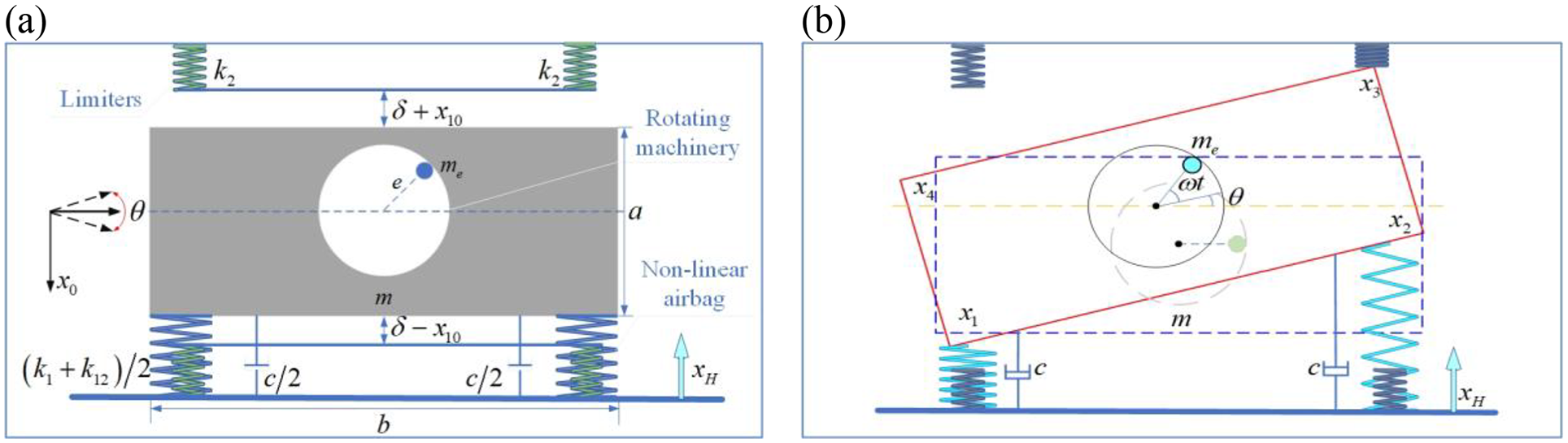
Schematic diagram of ship board rotating machinery coupling floating raft-airbag under heaving motion: (a) schematic diagram of a rotating machinery coupled floating raft-airbag-limiter system and (b) deformation diagram of a rotating machinery coupled floating raft-airbag-limiter system.
When a floating raft-airbag collides with a limiter, the displacements of the four pivotal points where the impact occurs are interconnected as follows

the total kinetic energy of the system can be expressed as

Where


In equation (3),

Thus, the total kinetic energy is as follows

The Rayleigh dissipation function of the system is given by

Due to adverse maritime conditions and extraneous variables, the system may experience substantial oscillations, potentially leading to collisions with the limiter. Therefore, it is suggested that the impact between the system and the limiter occurs in a frictionless manner, with energy loss confined to the intervals immediately before and after the impact. These collisions are characterized as vertical in nature. The magnitudes of the elastic forces within the limiters are as follows

In equation (8),

In equation (9), represents the static equilibrium displacement of rotating mechanically coupled floating raft-airbag system, which satisfies the following relationship

Then the limiter spring force of the system is

The force moment generated by the impact of the system with limiter can be expressed as

At the moment of impact, that is, at

In equation (13), symbols
The generalized force vector

In equation (14),

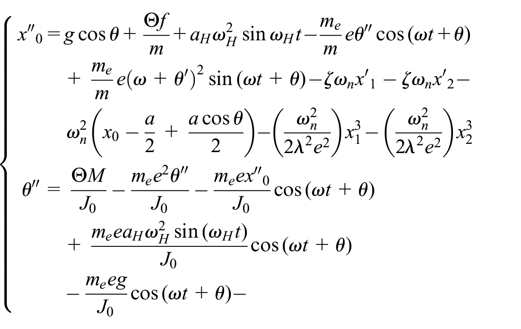
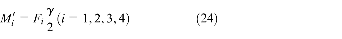
According to the II type Lagrange equation


The ship hull displacement due to heave follows a sinusoidal relationship as described in equations

Let

Dimensionless equations
In order to mitigate the influence of various physical quantity units and streamline subsequent analytical procedures, the introduction of characteristic length eccentricity and the transformation of differential equations into dimensionless form are necessary. The dimensionless parameters can be found in Table 1. In equation (20), the dimensionless quantization of the elastic force of the limiter can be expressed as

where

Dimensionless parameter expressions.

By the way, denote

In equation (23), the dimensionless equations for the four impact points are

In equation (12), dimensionless equation for the moment of force
Parameter analysis
Taking into account cubic nonlinear properties of airbag and segmented elastic force function of limiter, dimensionless vibration differential equations of the system are resolved employing 45th-order Runge-Kutta method. Dimensionless parameters of the raft-airbag coupled marine rotating machinery system are as follows:
Range of values for the ship heaving parameters.

In Figure 3, the impact of rotational speed on the system behavior is illustrated across different heaving amplitudes and frequencies, along with the steady-state response of the system at various heaving amplitudes. Specifically, Figure 3(a) highlights how heaving amplitude affects the system at diverse rotational speeds with a fixed limiter clearance and heaving frequency
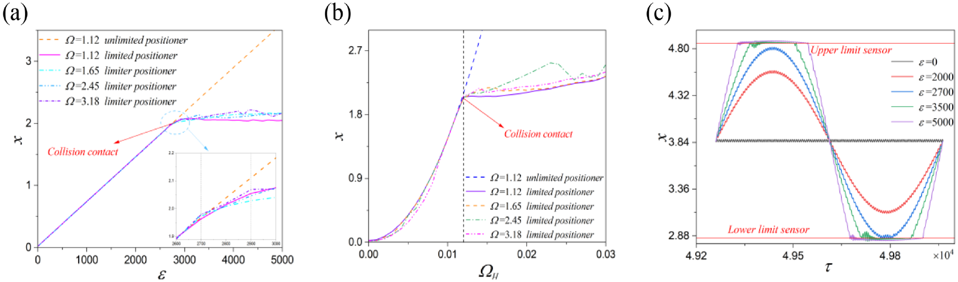
Steady state response of the system with different influences: (a) effect of speed on the system with different heaving amplitudes, (b) the effect of speed on the system with heaving frequencies varied, and (c) steady state response of the system with different heaving amplitudes.
Figure 3(b) illustrates impact of heaving frequency on the system at different speeds, while maintaining a fixed limiter gap
Figure 3(c) illustrates the steady-state response of the different heaving amplitudes, while maintaining constant limiter clearance
Influence of rotor speed on system dynamics with different heaving amplitudes
Figure 4 exhibits vibrational across various heaving amplitudes with constant parameters: heaving frequency
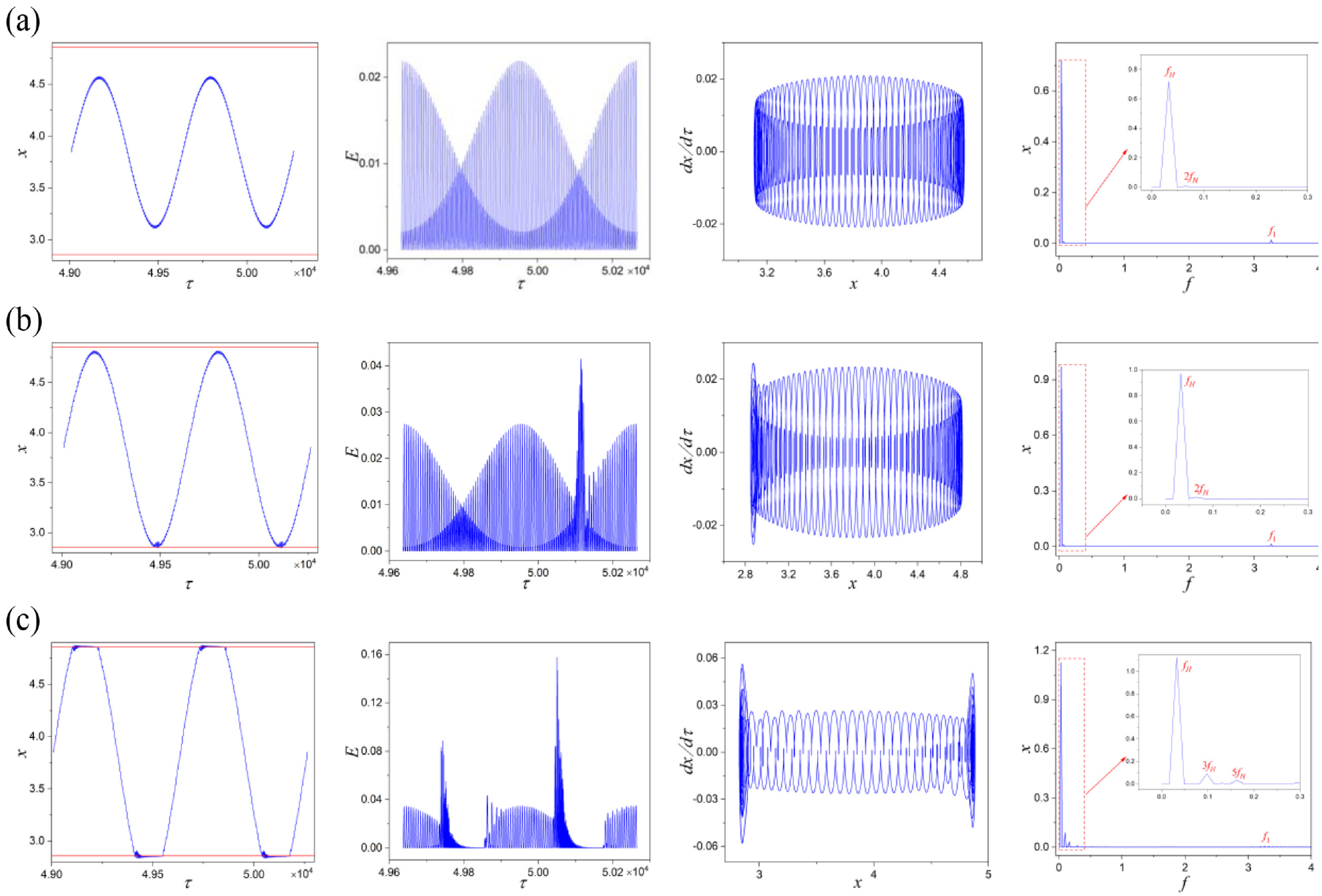
The steady-state response of the system, energy response curve, phase diagram, and spectrogram are displayed with
In Figure 4(b), the vibrational response of the system at a heaving amplitude of
Figure 4(c) shows the vibration response of the system at a heaving amplitude of
Figure 5 illustrates the steady-state response of the system across varying amplitudes of heave at rotor speed

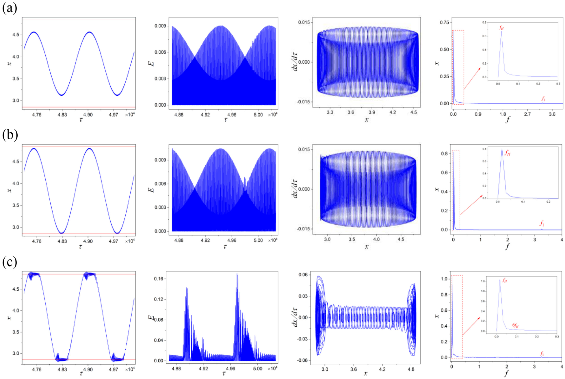
The steady-state response of the system, energy response curve, phase diagram, and spectrogram are displayed with
Figure 5(b) presents a time-domain response plot which reveals minor collisions with limiters, leading to a cessation of periodic variations in system amplitude. In contrast, post-collision alterations become more pronounced within the energy response curve. Specifically, there is an observed doubling of energy trajectory at lower rotational speeds while energy values within non-collision regions decline. This indicates that collisions facilitate an energy transfer from non-collision areas to collision zones. The increase in energy trajectory suggests heightened input from limiters and signifies an intensification of collision scenarios. Consequently, it can be inferred that due to these collisions, there is significant migration of energy from non-collision regions into collision zones. Furthermore, analysis through phase diagrams highlights abrupt transitions within trajectories occurring specifically within collision regions. The spectrogram indicates that solely heaving frequency
Figure 5(c), illustrates the time-domain response plot, which demonstrates that the system experiences simultaneous collisions with both the upper and lower limiters due to a progressive increase in heaving amplitude. The impact between the system and the limiters become more severe. In the energy response curve, these collisions result in abrupt changes that extend from the center of impact toward both sides. Notably, there is a pronounced increase in the maximum value of energy transition, indicating an extended duration of contact between the system and the stoppers, thereby leading to an increased energy input into the system. Abrupt changes are observed on both sides of the phase diagram trajectory. Due to inherent asymmetry within the system, alterations on the left side of this diagram are more significant than those on its right side; this suggests that collisions occurring on the left side are more intense. This observation aligns with findings from the energy response curve. Furthermore, analysis through spectrogram reveals a continuous spectrum emerging alongside six times the heaving frequency
Figure 6 illustrates steady-state responses across varying heaving amplitudes at constant rotor speed
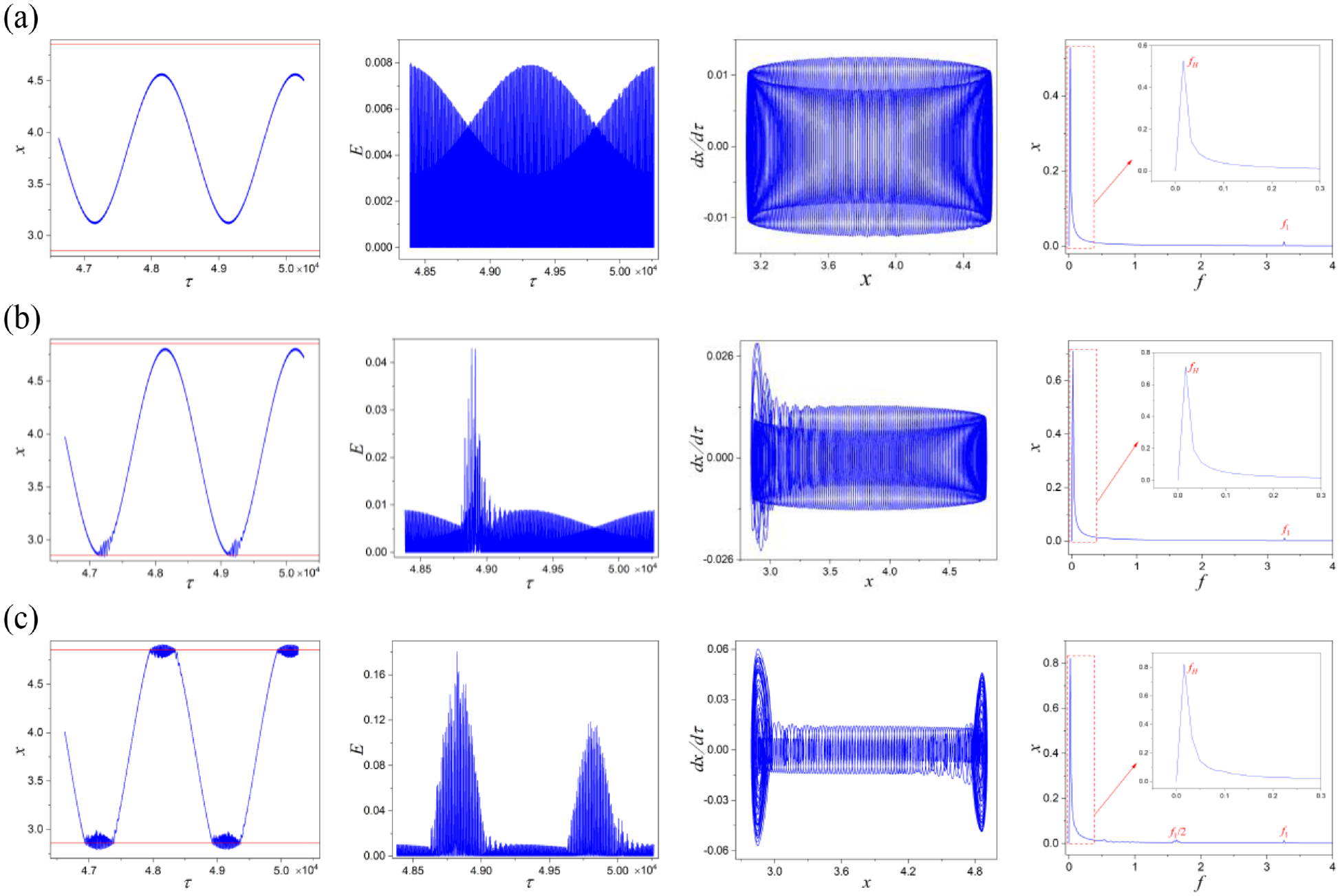
The steady-state response of the system, energy response curve, phase diagram, and spectrogram are displayed with
In Figure 6(b), the time-domain response reveals that as the heaving amplitude increases, minor collisions with the lower limiter occur. However, compared to conditions at rotational speed
In Figure 6(c), severe collisions between the system and bilateral limiters are evident from time-domain responses. The motion trajectory reveals that non-collision regions is time-domain trajectories are affected by these collisions, resulting in oscillatory phenomena. The energy response curve indicates a more intense collision scenario compared to speed
Figure 7 illustrates the steady-state response of the system across varying heaving amplitudes at a constant rotor speed
The steady-state response of the system, energy response curve, phase diagram, and spectrogram are displayed with
At a heaving amplitude of
The heaving amplitude of
Effect of limiter gap on system dynamics at different heaving amplitudes
System vibration arises from internal energy transfer and conversion processes that induce variations in system displacement. In steady state conditions, internal energy remains balanced. However, external forces disrupting this balance create an imbalance of energy and consequently shift its state. This section introduces time-averaged energy as a means to quantify average energy levels over specific timeframes. It is calculated by aggregating transient energies over a defined duration and averaging them within a specified time interval. The introduction of the concept of time-averaged energy allows for an efficient, accurate, and rapid reflection of changes in collision severity resulting from variations in system parameters. This research provides theoretical support for optimizing system parameters and diagnosing collision severity. The dimensionless time-averaged energy value

Where
Figure 8 illustrates the relationship between the displacement amplitude of the floating raft-airbag and the limiter gap for varying heaving amplitudes, along with corresponding time-averaged energy profiles for differing limiter clearances. In Figure 8(a), at a heaving amplitude of

Displays the plot of the system amplitude versus limiter gap for various heaving amplitudes at
Figure 8(b) depicts the relationship between system amplitude and limiter gap across varying heaving amplitudes. Notably, as heaving amplitude
Figure 8(c) illustrates how system amplitude progresses linearly with an increase in the limiter gap under a heaving amplitude
The effect of limiter stiffness on system dynamics at different heaving amplitudes
Figure 9 illustrates the steady state responses of the system under varying contact stiffnesses at a rotational speed of

Shows the time-domain response, localized magnification diagram, phase diagram, and spectrum of the system for different contact stiffnesses, (a)
By maintaining a constant limiter gap and increasing contact stiffness, as depicted in Figure 9(b) with a contact stiffness of
As the contact stiffness is further increased, as depicted in Figure 9(c), the contact stiffness
To more accurately describe the state of the system during the impact process, this paper analyzes the elastic potential energy of the floating raft-airbag system, which effectively detects the impact of rotating machinery on ships. This has significant implications for the vibration control of the system. Consequently, a third-order non-linear elastic potential energy of the airbag is introduced to characterize the changes in the system state during the impact process. The expression is as follows

After dimensionless of the introduced third-order non-linear airbag elastic potential energy, its expression is as follows

To mitigate the impact of rotor speed
Figure 10(a) to (c) illustrate the three-dimensional energy trajectories of the floating raft-airbag cubic non-linear elastic potential energy for different limiter stiffnesses. As contact stiffness increases, the energy trajectory associated with interaction between the system and the upper limiter begins to decrease in a vertical direction, while that for the lower limiter starts to increase. Additionally, there is a reduction in energy trajectory within non-impact region. This observation indicates that as contact stiffness rises, the severity of impact with the lower limiter gradually exceeds that with the upper limiter, resulting in an increased concentration of system energy near these limiters and intensifying impact conditions. With changes in contact stiffness, the energy trajectory of the system in the

Nonlinear elastic potential energy of floating raft-airbag with different contact stiffness (a)
Figure 10(d) illustrates the relationship between system amplitude variations and different contact stiffnesses as the heaving amplitude ranges from 2900 to 5000. As the contact stiffness increases from 10 to 30, a significant decrease in system amplitude is observed, indicating that an increase in contact stiffness effectively reduces the heaving amplitude of the system. However, when the contact stiffness reaches 50, further reductions in amplitude become minimal, suggesting that additional changes in contact stiffness have a negligible impact on system amplitude. The system consistently oscillates around a mean value as the heaving amplitude increases, which is attributable to limiters effectively dampening the system vibration amplitude. Moreover, variations in contact stiffness also exert a certain influence on vibration amplitude.
The time-averaged energy results for rotational speed
Conclusions
This paper focuses on the impact characteristics of a marine rotating machinery coupled floating raft-airbag-limiter system under heaving motion. Taking in account the influence of heaving motion, limiter clearance, and contact stiffness on the coupled floating raft-airbag system, a dynamic model of the asymmetric system with clearance under heave effects was established. The equations have been rendered non-dimensional, and numerical methods were employed to obtain the steady-state response of the system, to analyze the impact characteristics of the system under heave effects. The study mainly revealed the followings:
Under the effect of heaving motion, the motion state of marine rotating machinery coupled floating raft-airbag-limiter system transitions from quasi-periodicity to chaos as the heaving amplitude increases. Compared with the case without limiter, the limiter effectively suppresses the increase in the vibration amplitude of the system.
As the contact stiffness of the limiter increases, the elastic potential energy trajectories of the floating raft-airbag shift from the upper limiter toward the lower limiter under the influence of heaving motion. The energy trajectories concentrate toward the impact region, and collisions lead to significant changes in the energy trajectories in the angular direction.
Considering the influence of heaving motion, the marine rotating machinery coupled floating raft-airbag-limiter system experiences a linear increase in motion amplitude as the limiter gap widens. Once the vibration amplitude of the system reaches a certain level, the rate of increase in amplitude significantly decreases. The more severe the collisions experienced in the system, the higher the time-averaged energy values. Increasing contact stiffness within a specific range exerts a restraining effect on the system amplitude. When the system experiences severe collisions with the limiters, reducing the clearance between the system and the limiters can effectively control the amplitude of system vibrations without altering the state of motion of the system.
Footnotes
Appendix
Notation

| width of floating raft | |
| amplitude of pendulum swing | |
| length of floating raft | |
| friction | |
| rotor eccentricity | |
| instantaneous energy value | |
| hourly average energy value | |
| limiters elasticity | |
| dimensionless limiter spring | |
| acceleration of gravity | |
| dimensionless raft-airbag moment of inertia | |
| airbag-raft moment of inertia | |
| moment of inertia of a rotating machine | |
| floating raft-airbag stiffness | |
| airbag-flotation deck nonlinear stiffness | |
| limiter stiffness | |
| mass of the flotation raft and rotating machinery | |
| rotor mass | |
| limiters torque | |
| limiter dimensionless torque | |
| mass ratio | |
| generalized coordinate | |
| generalized force vector | |
| time | |
| systemic kinetic energy | |
| elastic potential energy of the airbag raft | |
| elastic potential energy of dimensionless airbag raft | |
| vertical velocity of rotating machinery | |
| horizontal speed of rotating machinery | |
| dimensionless displacement of the system | |
| static displacement of airbag rafts | |
| vertical displacement of floating raft | |
| collision point displacements | |
| vertical displacement of a heave | |
| absolute displacement | |
| instantaneous pre-collision speed | |
| instantaneous post-collision speed | |
| dimensionless displacement of the collision point | |
| dimensionless limiter gap | |
| dimensionless width of airbag-float raft | |
| dimensionless length of airbag-float raft | |
| dimensionless vibration amplitude | |
| rotor speed | |
| heaving frequency | |
| intrinsic frequency of an air-bagged raft | |
| scale factor | |
| deflection angle | |
| damping ratio | |
| feature length | |
| dimensionless time | |
| limiter contraction amount | |
| dimensionless limiter contraction amount | |
| collision factor with upper limiters | |
| collision factor with lower limiters | |
| dimensionless rotor speed | |
| dimensionless heaving frequency | |
| dimensionless intrinsic frequency |
Handling Editor: Jianjun Feng
Declaration of conflicting interests
The author(s) declared no potential conflicts of interest with respect to the research, authorship, and/or publication of this article.
Funding
The author(s) disclosed receipt of the following financial support for the research, authorship, and/or publication of this article: This work was supported by the National Natural Science Foundation of China (Grant Nos. 11972282 and 12002267).