
Abstract
The whirlwind milling (WM) technology is a competitive machining method, especially for large screws. A rotating large screw subjected to a rotating and moving WM cutting force has complex dynamics and formation. In the study, the WM cutting forces in radial, tangential, and axial directions were firstly acquired using a self-developed testing system. Then, the cutting vibration was modeled in consideration of the WM unique constraint, and the deflections in different directions were analyzed in detail. Lastly, the surface topography and roughness under cutting were geometrically modeled by superimposing the radial deflection on the static forming surface. Compared to single-factor experiments, the results demonstrated the consistency between surface roughness and experimental data. Therefore, the established vibration and surface roughness models are reasonable and effective for predicting, and thus favorable and beneficial for the optimization in whirlwind milling a large screw.
Introduction
The demand for large screws has become increasingly urgent in the development of large equipment manufacturing. 1 Compared with turning and grinding, whirlwind milling (WM) is considered as one of the most promising technology for large-screw processing because of its great flexibility, high material removal rates and environmentally favored requirements. For improving the surface integrity, the cutting vibration, and surface roughness in WM are requisites in further studies.
Several theories and dynamic models have been developed to study the vibration. Chen 2 proposed a dynamic model of a helical gear pair system, and applied Lagrange’s equation and Runge–Kutta method. Then Wang et al. 3 developed a non-contact electromagnetic loading device, which measures the transient loading force of a high speed motorized spindle. Park and Hong 4 developed an energy model for Euler–Bernoulli, Rayleigh, and Timoshenko beams. Bazehhour et al. 5 used a analytical approach to present the free lateral vibration of a rotating Timeshenko shaft with various boundary conditions. Metsebo et al. 6 applied the fast Fourier transform and phase trajectory to focus on the dynamics of a rotor–ball bearing system. Wang et al. 7 explored a point vector method to express the shaft dynamic response using homogeneous boundary conditions. Zhang et al. 8 developed a new formulation with an equivalent internal damping when a slender beam was subjected to large deformations. While for WM, most studies were focused on the tool tip trajectory. Ni 9 established the transforming relationship between tool profile and thread raceway profile. Li et al. 10 obtained a accurate vibration model of AMB-rotor system, and verified on a test rig.
More studies have also focused on the formation of the machined surface. Duc et al. 11 evaluated the variance of surface roughness in hard drilling. Strano et al. 12 and Boschetto et al. 13 developed a mathematical model to predict the surface roughness in selective laser melting, respectively. Considering with the system vibration, Shiau et al. 14 predicted the surface roughness in grinding a ball screw under a moving force. Wojciechowski et al. 15 found that the high surface finish in precise milling was strictly dependent on cutting force values. Twardowski et al. 16 modeled the surface roughness through a kinematic–geometric projection of cutting edge in high-speed milling. Asiltürk and Çunkaş 17 predicted the surface roughness combining multiple regression with the ANN method. Shalaby et al. 18 proposed a mechanistic model based on Merchant’s analysis. Zein and Irfan 19 developed a analytical model for surface roughness and investigated the effect of cutting parameters in orthogonal experiments. Marques et al. 20 revealed experimentally that the surface roughness is in reduction trend with increasing cutting speed. Ghosh et al. 21 utilized RSM to study the relationship between the input cutting parameters and output surface roughness in milling, and as Guo et al. 22 did in WM. Guo et al. 23 developed a static surface roughness model in WM.
In WM, although some studies on the tool tip trajectory and static surface formation have been examined, the cutting vibration caused by WM forces was ignored, and the resulted forming information of screw was still lack. Thus, the present study aims to develop effective models of cutting vibration and surface information based on tested cutting forces.
Materials and methods
Figure 1(a) showed a 10-m WM machine for experiments. The same tools in Figure 1(b) are symmetrically mounted on the tool holder. Tools rotates homodromously at high speed as screw at low speed. Figure 1(c) illustrates the partial enlarged detail of WM. The material of workpiece is GCr15 (similar to AISI 52100). It was treated by surface low-frequency quenching, and the hardness is HRC 62. The tool employed in the cutting tests were polycrystalline cubic boron nitride with a negative 8° rake angle. The wedding agent was titanium nitride, and the granularity 2 mm. The high CBN content (85%) was used as recommended. In testing, the WM cutting forces in radial, tangential and axial directions were acquired by a team self-developed testing system. 24
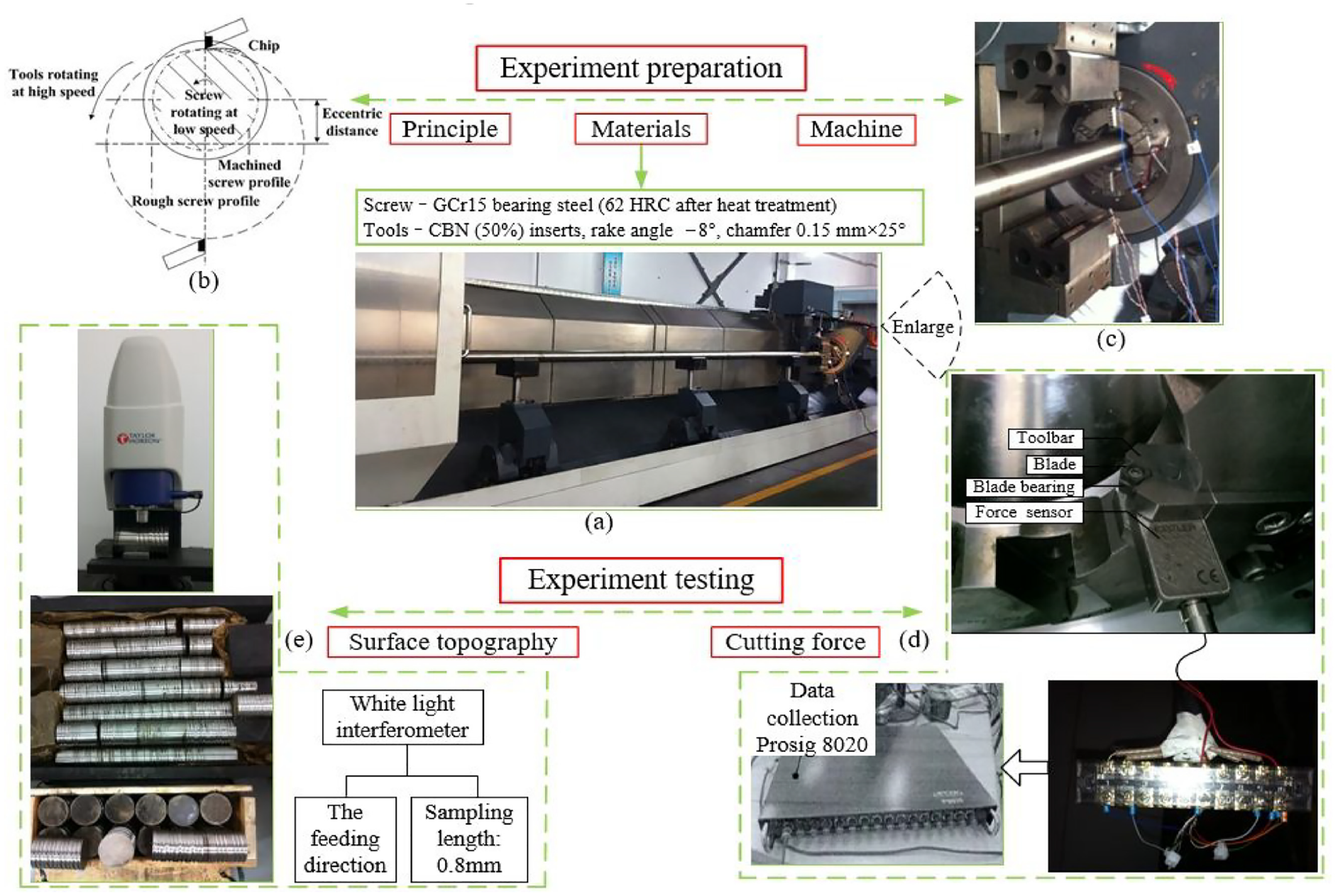
The (a) 10 m machine, (b) working principle, (c) partial enlarged detail, (d) cutting force measuring installation, and (e) surface roughness testing of WM.
In Figure 1(d), the tool is in split type. It contains cutter body like toolbar, cutter blade and blade bearing which connected by screw. A 3D piezoelectric force sensor was used in the cutting force measurement, which was fastened between the tool apron and cutter holder. Passing by a multi-channel slip ring and filtered by a data acquisition system (P8020), the force signals were detected through a force sensor with built-in charge amplifier, and a cutting time of 1.5 s for force signal acquisition. After WM, the surface topography and roughness can be obtained by white light interferometer in Figure 1(e). The values of cutting force and surface roughness were all tested three times and averaged.
Modeling cutting vibration and surface topography
Modeling cutting vibration
In WM, a large screw is mounted and driven at a rotating speed nw. Both ends of the screw are configured with a clamped–hinged (left–right) boundary, whereas the remaining part is supported by three floating grippers and two clasping devices. In Figure 2, the two frames, a fixed reference frame X–Y–Z and a rotating reference frame x–y–z, are utilized to describe the system motion. The Z- and z-axes are col-linear, and the two reference frames have a rotating angle Ω difference at the Z-axis. The Fw, Fv,. and Fu represent the three cutting force components acting on the screw in radial, tangential and axial directions, respectively. The deflections by the cutting force are classified as three translational (

Schematic of WM.
In any cross section of the screw, the instantaneous axial displacement U, radial V, tangential W, tangential rotational
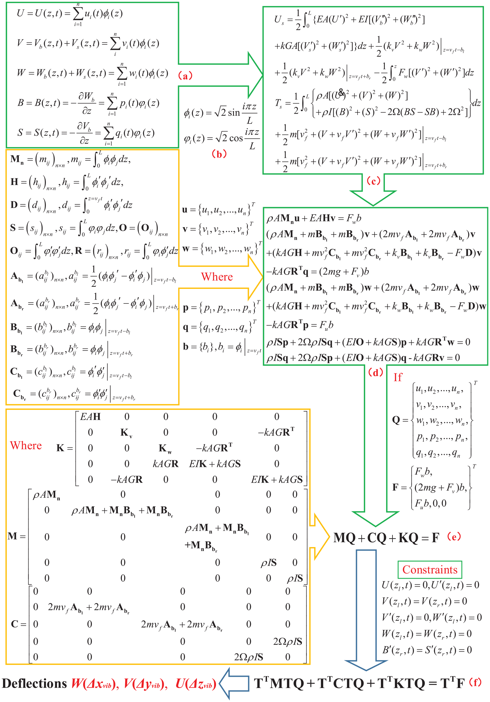
Flow chart of the cutting vibration model (a) the instantaneous displacements, (b) the corresponding assumed shape functions, (c) the potential energy and kinetic energy, (d) the motion equations, (e) the motion equation in a matrix form, (f) the transform equation, with constraints of the cutting vibration model.
For the motion system, the two energies, potential energy Us and kinetic energy Ts, are expressed in Figure 3(c). The potential energy Us includes the shear deformation, pure bending and axial deformation. The kinetic energy Ts includes the axial, translational, rotational inertia and gyroscopic effect. By the Lagrangian approach, the motion equations can be obtained (Figure 3(d)) and simplified (Figure 3(e)).
All motions should meet the constraints on the screw. The motion equation under constraints is shown in Figure 3(f). Thus, the deflection
Modeling surface topography
Most of surface topography models are examined in conventional cutting, such as turning and milling, and great progress has been achieved over the past years. However, reports on surface topography under cutting vibration in WM was little reported.
For modeling the cutting trajectory (Figures 1 and 4(a)), six coordinate systems shown in Figures 2 and 4(a) were utilized. In Otl (Xtl, Ytl, Ztl), Otr (Xtr, Ytr, Ztr), and Otc (Xtc, Ytc, Ztc) local coordinate systems, the formula of points on different positions of the tool are expressed in Figure 4(b). By matrix Mwdl, Mwdc, and Mwdr, points on three tool’s local coordinate systems can be converted into the Owd (Xwd, Ywd, Zwd) frame in Figure 4(c). Firstly in Figures 1 and 4(d), the transformation Otf (Xtf, Ytf, Ztf)→Owf (Xwf, Ywf, Zwf) can be achieved by matrix Mwftf . Secondly in Figures 2 and 4(d), the transformation Otf (Xtf, Ytf, Ztf)→Owd (Xwd, Ywd, Zwd) can be expressed by matrix Mtfwd. Then in Figures 3 and 4(d), the transformation Owf (Xwf, Ywf, Zwf)→Owd (Xwd, Ywd, Zwd) can be attained by matrix Mwfwd. If the tool had a negative rake angle γ, the transformation matrix can be expressed in Figure 4(d-4).

Flow chart of the surface topography model under cutting vibration (a) coordinate systems and kinematical relation, (b) tool’s points in tool coordinate system, (c) matrix transformation Ot (Xt, Yt, Zt)→Owd (Xwd, Ywd, Zwd), (d) matrix transformation Otf (Xtf, Ytf, Ztf)→Owf (Xwf, Ywf, Zwf), (e) transformation with vibration, (f) final transverse equations, (g) discretization of workpiece, (h) machined points with vibration, (i) radial length of machined workpiece, (j) residual scallop height, (k) final residual height, of the surface topography model under cutting vibration.
When considering cutting vibration in WM, the matrix Mwdh-vib (Figure 4(e)) integrated the deflections by cutting vibration into the forming of surface topography.
Finally, the finishing tool points under Owf (Xwf, Ywf, Zwf) can be modeled by substituting the above transformation matrices into expressions (Figure 4(f)). Thus combining with points on the tool in Figure 4(b), all points on the workpiece under cutting vibration can be expressed by Figure 4(h).
For describing points in the cutting area, the workpiece is discretized in circumferential and radial directions (Figures 1 and 4(g)). The workpiece in the radial direction and circumferential direction are separately discrete as R and S equal parts. Accordingly, the cutting track on the workpiece is represented by a series of discrete points Rrs (r = 1, 2,…, R; s = 1, 2,…, S). All discrete points on the workpiece can be calculated in the Figure 4(g-2).
Through the superimposition of the tool contour on the workpiece surface, the lower contour between two adjacent cuts namely the (i)th and (i + 1)th cutting is defined to generate a whirlwind-milled surface. In Figure 4(i), the radial lengths mapped on the workpiece are respectively marked lvib,i(r, s) in the (i)th cutting and the lvib,i + 1(r, s) in the (i + 1)th cuting. By comparing rx(r, s) with r limit , the scallop height hi(r,s) can be expressed in the Figure 4(j). The least scallop height Hi + 1(r, s) in two adjacent cutting is chosen as the final machined scallop height, shown in Figure 4(k).
Deflection simulations and discussion
The governed V(Ivib) formula in Figure 3(f) was numerically solved by the Runge–Kutta method, and the first six shape functions were used to obtain the deflections by the WM cutting force. Table 1 lists the parameters. In this section, the enclasping device in WM was examined in terms of the enclasping torque Mf.
Parameter values in the simulation.

On maximum radial deflection
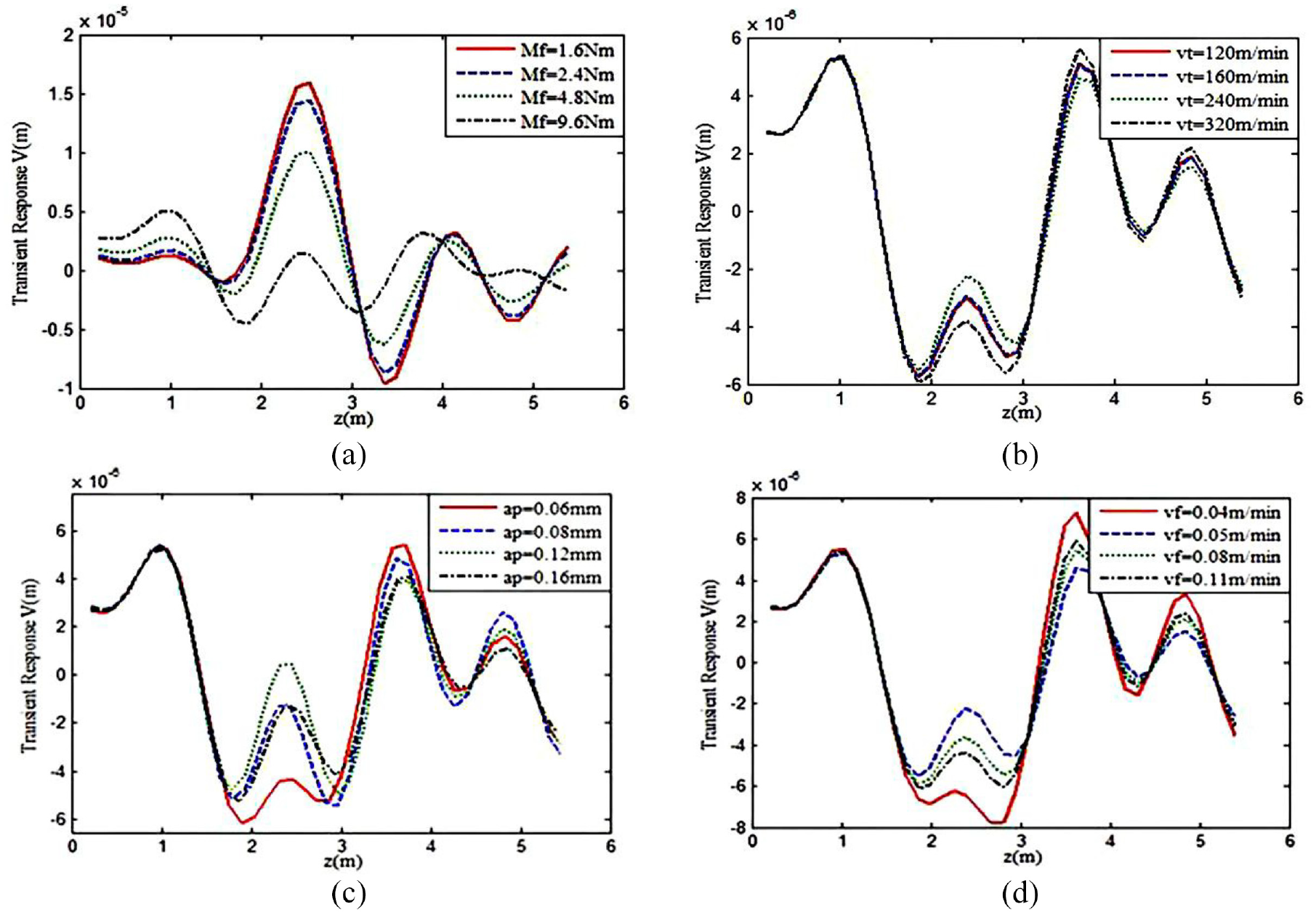
Deflection V under different: (a) enclasping torques, (b) cutting speeds, (c) cutting depths, and (d) feeding speeds.
For cutting parameter (Figure 5(b)–(d)), the
Simulation and experiment validation
Based on the analysis of

Predicted Ra-pre and measured Ra-mes surface topography under various enclasping torques: (a) Mf = 1.6 N·m, (b) Mf = 2.4 N·m, (c) Mf = 4.8 N·m and (d) Mf = 12.8 N·m.
As Mf = 1.6 N·m, the workpiece undergoes significant fluctuation under the WM force. The machined surface exhibits a strong vibration in Figure 5(a), and the tested surface roughness is Ra 0.42 μm. When it increases to 3.2 N·m, the waviness and roughness of the workpiece are all reduced. When the torque continuously increases to 12.8 N·m, the surface roughness tends to stabilize.
In Figure 7, the tested surface was obtained at a lower cutting speed of 160 m min−1, which is high and uneven. By contrast, the tested surface at 240 m min−1 is relatively uniform. As the cutting speed increased, the tested Ra is reduced from 0.33 to 0.19 μm. Thus, the Ra shows a maximum under vt = 160 m min−1 and a minimum under vt = 240 m min−1. After data comparison, the errors of the estimated and measured values of the surface roughness are within the 10% range.

Predicted Ra-pre and measured Ra-mes surface topography under various cutting speeds: (a) vt = 120 m min−1, (b) vt = 160 m min−1, (c) vt = 240 m min−1, and (d) vt = 320 m min−1.
Conclusion
In this study, the surface topography and dynamic characteristics of a rotating large screw were modeled and investigated when the screw is subjected to a moving and rotating WM cutting force. The results can be summarized as follows:
The established cutting vibration model considered the complicated constraints including floating support and enclasping device. The radial response in the case of the enclasping torque is evidently different from that of cutting parameters. The maximum radial deflection decreases with the increase in enclasping torque.
Based on the analysis of radial deflection, the surface topography was modeled by superimposing the radial deflection on the machined surface. The surface topography and roughness were simulated under various parameters. After data comparison, the errors of the estimated and measured values of the surface roughness were within the 10% range.
Research indicated that the condition under clasping torque of 12.8 N·m, cutting speed of 240 m min−1, cutting depth of 0.12 mm and feeding speed of 0.05 m min−1 is preferred both in the simulation and experiment. Thus, the cutting vibration model and surface topography model are verified to be reasonable and effective for prediction and optimization.
Footnotes
Appendix
Handling Editor: Chenhui Liang
Declaration of conflicting interests
The author(s) declared no potential conflicts of interest with respect to the research, authorship, and/or publication of this article.
Funding
The author(s) disclosed receipt of the following financial support for the research, authorship, and/or publication of this article: This work was supported by the National Natural Science Foundation of China [grant number 51805243, 2018].