
Abstract
There is a growing interest in developing an advanced technique to manufacture titanium alloy for larger holes in the aviation and marine industries. While the application of larger holes is limited due to the low machinability and high cost. The deep-hole trepanning is investigated to manufacture the titanium alloy in a high-efficient low-cost manner, and the technical challenges during the deep-hole trepanning process are studied in this article. Designs of the deep-hole trepanning tool and experiments under different cutting speeds and feed are carried out. Chip morphology, axial cutting force, and tool wear are analyzed. The optimal process parameters are achieved. This study provides a practical solution to process titanium alloy for potential industrial applications.
Introduction
Titanium alloy pipes are widely used in many industries such as aerospace, shipbuilding, petroleum exploration, and biomedical instrumentation due to their high strength-to-weight ratio, high-temperature resistance, and excellent erosion resistance. 1 To ensure the reliability and structure life of the titanium alloy pipe, most of the titanium alloy seamless pipes are machined from forged titanium alloy rods. 2 The mandrel mill process and boring trepanning association (BTA) drilling are the main processes to obtain the large-diameter seamless pipe. 3 While there are several problems, such as high equipment requirements, complicated procedures, low yield, and high cost, in the mandrel mill process. 4 This is mainly due to the narrow deformation temperature range and high deformation resistance of titanium alloy. BTA drilling usually leaves chips to be removed and could cause considerable material wastage. When it comes to larger holes, deep-hole trepanning is often adopted. Deep-hole trepanning is a special BTA drilling that produces a solid core where drills out of the middle of the hole and uses that solid core for other applications. In addition to reducing the production cost and improving material utilization, trepanning tools require less energy compared to other hole drilling solutions. 5 Liu et al. conducted deep-hole trepanning experiments for TA1 titanium alloy and investigated the effect of process parameters on axial force and torque. 6 Peng and Zhang processed the difficult-to-machine material 0Cr17Ni4Cu4Nb using short arc trepanning. 7
The main evaluation index of deep-hole trepanning is its achievable hole quality. 8 The achievable hole quality is principally affected by the tool, workpiece material, and process parameters. 9 In addition, the chip morphology, tool wear and cutting force is greatly determined by the geometric parameters of the tool and process parameters. 10 The suitable process parameters (e.g. feed rate and cutting speed) can improve the tool wear and chip morphology. 11 The range of the feed rate and cutting speed is mostly determined by the workpiece material and machining process.
Titanium alloy is a typical difficult-to-machine material and its chip morphology changes in the different machining processes. 10 In high-speed cutting, the discontinuous chip, long curling chip, and continuous chip are produced at low cutting speed, medium cutting speed, and high cutting speed respectively. 12 In the dry drilling, the spiral cone chip is the most typical chip for Ti6Al4V alloys. During this process, with the increase of the feed rate, the chip length decreases, and cutting speed has little effect on the chip morphology. 13 In the BTA process, as the feed rate and cutting speed increase, the chip thickness increases and decreases respectively within a certain range. 14 Variation in process parameters also directly affects the cutting force. 15 The cutting force increases with the increase of the cutting speed and feed rate in the trepanning process. 16 The research on the relationship between process parameters and chip morphology, cutting force is relatively less about titanium alloy deep-hole trepanning. Therefore, in order to solve the problem encountered in the process of deep hole opening of TC10 titanium alloy. Firstly, the experiments were designed based on the deep-hole trepanning system. Secondly, the chip morphology and cutting force can be improved by adjusting the feed speed and cutting speed. In addition, the tool wear is also analyzed. Finally, the optimal parameters are obtained.
Experimental procedures
Deep-hole trepanning for titanium alloy TC10 includes the deep-hole trepanning system, design of the deep-hole trepanning tool, and process parameters. TC10 (Ti-6Al-6V-2Sn-0.5Cu-0.5Fe) titanium alloy, the corresponding American brand Ti-662, is an
Chemical compositions of TC10 alloy.

Mechanical properties of TC10 alloy.

Deep-hole trepanning machining system
The deep-hole trepanning machining for titanium alloy adopts an external chip discharge deep-hole trepanning system. The system is mainly composed of a deep-hole drilling machine, a deep-hole trepanning tool, and a chip collection and transfer system, as shown in Figure 1. In this system, the workpiece is rotated and the drilling rod is fed. The coolant is applied through the rear of the drilling rod. It flows from the gap between the inner wall of the drilling rod and the outer wall of the solid core to the cutting zone to reduce the temperature of the cutting area. Then the chips are discharged from the inner wall of the workpiece and the outer wall of the drilling rod.

Deep-hole trepanning system.
Material and structure of the deep-hole trepanning tool
Due to the poor cutting performance and heat conductivity of the titanium alloy, the chosen cutting speed is relatively low. During the cutting process, the jagged chips cause periodic changes in the cutting force, and the effect of the cutting force on the tool is relatively large.13,14 Cemented carbide YG8 was selected as the tool material due to the high flexural strength, good impact resistance, anti-vibration performance, and low allowable cutting speed.
The structure of the deep-hole trepanning tool includes the single-tooth tool and multi-tooth tool. Deep-hole trepanning with a multi-tooth trepanning tool produces more vibration than a single-tooth trepanning tool. 18 In addition, the overlap between the different teeth increases cutting force, indirectly increasing the cutting power and requirements for the machine tool. Therefore, it is more suitable to use a single-tooth trepanning tool in the deep-hole trepanning process for titanium alloy. The single-tooth trepanning tool shows in Figure 2.

Single-tooth trepanning tool: (a) the physical object of the trepanning tool, (b) geometric parameters of chip-breaker, and (c) five step-like teeth.
Considering the characteristics of titanium alloy, including high specific strength and thermal strength, as well as small deformation coefficient and elastic modulus. It is advisable to select a small rake angle, large relief angle, and large cutting edge angle for machining titanium alloy, where helps that the cutting edge is sharp and wear-resistant, and chip deformation can be reduced. Therefore, according to the selection conclusion of literature, 17 the rake angle is 7°, the relief angle is 12°, the cutting edge angle is 80°, and the inclination angle is 0°.
For deep-hole trepanning of titanium alloy, chip control is very important. The control of the chip is mainly realized by the chip curling or the chip separation. The chip curling is a method based on the reasonable design of the geometric parameters of the chip-breaker. The parameters of the chip-breaker are shown in Figure 2(b). The width (Wn) of the chip-breaker ranges from 1.8 to 2.3 mm. The width of the tooth near the center of the hole should have a smaller value, whereas the outer tooth should have a larger value. The depth (Hn) of the chip-breaker is 0.55 mm, and the arc radius (Rn) generally ranges from 0.5 to 0.8 mm. The chip separation adopts an axial multi-step teeth, which means the cutting edge is offset from each other in the axial direction with different depths to separate chips. The cutting edge generally has four or five step-like teeth, and the total width of the cutting edge is 15 mm. Figure 2(c) shows the structure and size of the five step-like teeth.
Process parameters
The process parameters of deep-hole trepanning include the cutting speed, feed rate, coolant type, and the guiding hole dimensions. The initial set of process parameters was based on practical experience19,20 and theoretical research.21,22 Liu et al. 9 investigated deep hole drilling of TC10 alloy with cutting speeds ranging from 24 to 43 m/min. Zhu et al. 23 studied the performance characteristics in drilling Ti6Al4V alloy with cutting speeds ranging from 25 to 55 m/min and feed rate varying from 0.05 to 0.13 mm/r. Thil et al. 24 chosen the feed rate at 0.145 mm/r, and Li et al. 14 selected the feed rate between 0.04 and 0.12 mm/r. Liu et al. 9 recommended the feed rate from 0.1 to 0.2 mm/r. From this, it can be found that the cutting speed is mostly between 24 and 55 m/min and the feed rate is mainly between 0.04 and 0.2 mm/r. However, considering the poor machining environment of deep hole trepanning and excessive temperature caused by the high cutting speed, which will affect the machining quality. Therefore, the cutting speed which is lower than 30 m/min was selected, and the feed rate is selected from 0.05 to 0.20 mm/r.
During the deep-hole trepanning process, the coolant accessing the chips, the trepanning tool, and the workpiece can remove the heat from their surfaces. The cooling and lubrication of the coolant could prevent the tools from reaching higher temperatures, which reduce the tool softening and wearing, and the coolant also can flash the chips away from the cutting zone. To choose an appropriate coolant, it is better not to use chlorine-containing coolant to prevent the formation of toxic substances and hydrogen embrittlement of titanium alloy material, which greatly reduces the cutting performance of the material. Water-based coolants should also be avoided, as they promote the formation of a built-up edge on the cutting edge at high temperatures. Extreme high-pressure soluble oil can be used as a coolant because of its relatively good lubricity and adaptability to harsh machining environments. In this paper, we use 1:1 mixture of 10# and 20# mechanical oil for deep hole trepanning of titanium alloy, which has both the low viscosity of 10# mechanical oil and the lubricity of 20# mechanical oil. 25 Compared to traditional deep-hole drilling, trepanning requires less pressure but a greater flow rate. As the depth of the hole increases, the pressure and coolant flow rate also need to be increased, and the value refers to BTA deep-hole drilling.24,26
In addition to cutting speed, feed rate, and coolant type, the guide of the trepanning tool is the key technology to determine whether the deep-hole trepanning process can be carried out normally. The annular grooves are commonly used to guide the trepanning tool into the workpiece and prevent deflection of the cutting hole. The annular groove was pre-processed on the workpiece and its structure is shown in Figure 3. To ensure the inner and outer cutting edges of the tool cut at a different time during the drilling, the outer diameter of the guiding hole needs to be 1–2 mm smaller than the dimension of the inner edge of the trepanning tool. In addition, to enable the introduction of the trepanning tool easily during cutting, the end of the shaft needs to be chamfered at an angle of 30° with a length of 5 mm. The annular groove tolerance is H9 and is designed according to the machining requirements. The surface roughness Ra is 3.2 μm, and the depth is within 20~80 mm.
Structure of the annular groove of the workpiece.
Results and discussion
In this section, chip morphology, chip discharge, axial cutting force, wear and failure of the trepanning tool were analyzed.
Chip morphology and chip discharge
TC10 bar was used as an example of the deep-hole trepanning process in this experiments, leaving a solid core out of the middle of the drilling hole, and the TC10 bar with a diameter of 165 mm and a length of 2000 mm. The drilling hole diameter was 95 mm and the solid core diameter was 65 mm. The deep-hole trepanning of the TC10 titanium alloy was conducted at different cutting speeds (less than 30 m/min) and feed rates (0.05–0.20 mm/r). Five types of chip morphology were formed (shown in Figure 4), which were squeeze chips, tear type chips, unbroken continuous chips, spiral chips, and fragmented chips. Spiral chips, and fragmented chips were prone to be removed from the trepanning process.

Chip morphologies of TC10 titanium alloy: (a) squeeze chips, (b) tear type chips, (c) unbroken continuous chips, (d) spiral chips, and (e) fragmented chips.
The squeeze chips were shown in Figure 4(a) when the cutting speed was between 14.7 and 27.0 m/min and the feed rate was less than 0.10 mm/r. Once squeeze chips are formed, it is easy to cause chip jamming regardless of the cutting speed. When the feed rate was greater than 0.15 mm/r or the cutting speed was greater than 27.0 m/min, tear type chips were formed shown in Figure 4(b). During this trepanning process, severe vibrations and wear of the tool occurred and could easily cause the tipping of the trepanning tool. Figure 4(c) showed the chip morphology when the feed rate is 0.10 mm/r, where unbroken chips were formed. The chip discharge and drilling processes were still relatively stable, but the unbroken chip had the tendency to wrap around the drilling rod and caused further chip jamming. Figure 4(d) showed the spiral chip when the feed rate is between 0.10 and 0.15 mm/r. In this case, the chips can be automatically separated. It resulted in stable chip discharge and drilling processes when the cutting speed was below 27.0 m/min, which was in favor of long-time trepanning processing. However, it cannot realize periodic chip breakage during the trepanning process and excess of chip length could occasionally cause chip jamming. This issue was resolved by increasing the depth of the chip breaker, which led to the automatic chip breakage; its chip morphology was shown in Figure 4(e) when the feed rate remains 0.10 to 0.15 mm/r and the cutting speed is below 27 m/min.
To ensure chip flow and discharge, the cutting speed varied from 14.7 to 27 m/min, and the feed rate ranged from 0.1 to 0.15 mm/r. Another way to ensure the chip discharge is to increase the flow rate of coolant. It can improve the rigidity of the machining system, but also reduces the periodicity of automatic chip breakage to reduce the chip length. However, the influence of the flow rate of the coolant on the chip separation of the trepanning tool is not obvious. Therefore, when processing titanium alloy materials using deep-hole trepanning, if the cross-sectional area of the oil passage was relatively big and the flow rate of the coolant was relatively higher, it would be beneficial to chip discharge and thus make the drilling process more stable.
Axial cutting force
The axial cutting force has a great impact on the deep hole trepanning process, affecting the wear of the trepanning tool, the dimensional accuracy and surface quality of the hole and solid core, the power consumption of the machine tool, and the rigidity of the processing system, etc. Therefore, it’s meaningful to control the axial cutting force within a certain range to maintain a stable process. The range of the axial cutting force for different cutting speeds and feed rates were shown in Table 3. The maximal cutting force was believed to be the predominant cutting load that the tool and workpieces endured during drilling. It can be seen that the fluctuations of axial cutting force during deep-hole trepanning are relatively large. As the feed rate increased, the axial cutting force increased greatly, whereas, with the increase in cutting speed, the axial cutting force of the tool did not change significantly. So the feed rate has a greater influence on the axial cutting force than the cutting speed.
Axial cutting force during deep-hole trepanning of TC10 titanium alloy.

Wear and failure of trepanning tool
In deep hole trepanning, tool wear is inevitable. The failure mode of the trepanning tool is cohesive wear and tipping. The failure process of the trepanning tool is shown in Figure 5. When the feed rate is between 0.10 and 0.15 mm/r and the cutting speed is less than 27 m/min, due to the high chemical activity of titanium alloy materials, it has a strong affinity with cemented carbide tool materials. As shown in Figure 5(a), In the initial stage of the deep-hole trepanning, high temperature and pressure will be generated in the contact zone between the trepanning tool and the workpiece due to the low thermal conductivity of titanium alloy. It creates the conditions for the chips to bond to the trepanning tool, allowing the bonding material to continue to accumulate on the surface of the trepanning tool. Localized bonding between two contacting surfaces may result in the detachment of chip fragments and material transfer to the surface of the trepanning cutting tool to form asperities. The continuous chips slide along asperities under high pressure, which will lead to the breaking off of the asperities junction. This may result in the cohesive wear of the trepanning tool. With this process parameter, this type of wear can be removed by sharpening, and the tool can be put back into service after sharpening. As shown in Figure 5(b) to (d), when the feed rate is greater than 0.15 mm/r or the cutting speed is greater than 27 m/min, the deep hole trepanning process produces violent vibration, which makes the tool keep impacting the workpiece surface, and micro-cracks are generated and propagated on the trepanning tool. As the cutting process continues, eventually lead to the tipping of the trepanning tool due to transient thermal and mechanical impacts, and this wear is difficult to repair by sharpening.

Failure process of the trepanning tool: (a) cohesive wear, (b) micro-cracks, (c) crack propagation, and (d) tipping.
Finished products
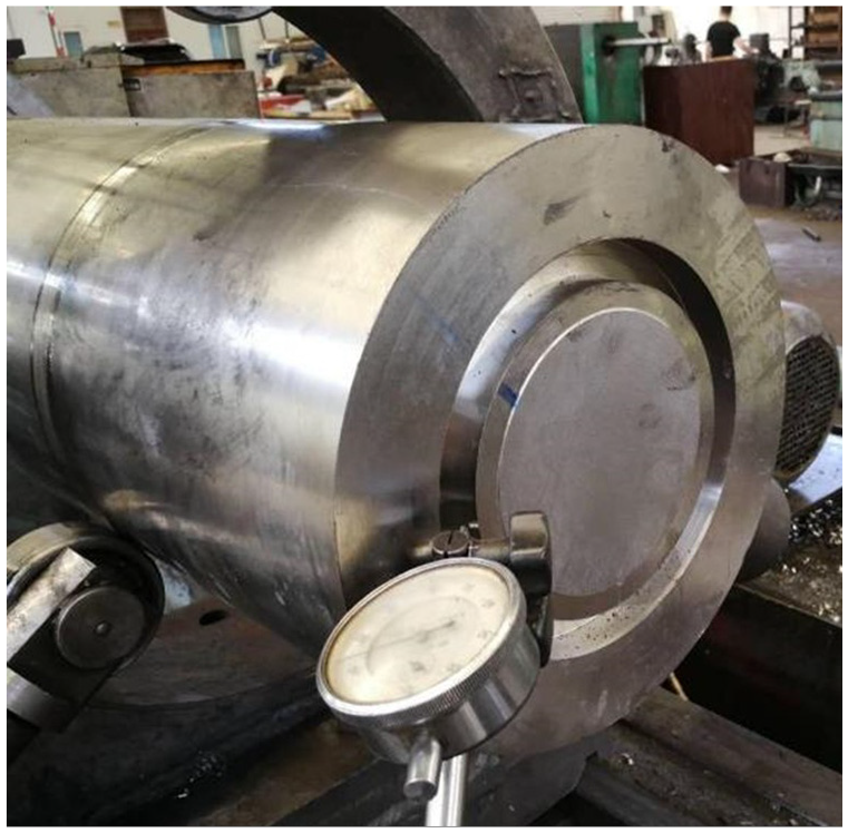
Figure 6(a) shows the TC10 bar before deep hole trepanning. When the feed rate is between 0.10 and 0.15 mm/r and the cutting speed is less than 27 m/min, the experiments were carried out according to the process conditions as mentioned above, and the finished products of TC10 are shown in Figure 6(b). The final product is divided into a TC10 tube and a TC10 solid core, of which the TC10 solid core is the saved raw material that can be used for new processing. The dimensional accuracy of the deep hole of the TC10 tube can reach IT10, the surface roughness is measured at the end of the TC10 tube and can reach Ra 6.3 μm, the straightness can reach 0.5 mm, and the coaxiality is less than 0.2 mm, which meets the designer’s requirements.

TC10 titanium alloy: (a)TC10 bar and (b) deep-hole trepanning product.
This study provides an alternative solution to manufacture the titanium alloy material with high strength, low conductivity, and high cost in an efficient and cost-effective manner. At the same time, 165 mm outer diameter and 30 mm of radial material removal can achieve 81.81% material utilization.
Conclusion
In this paper, deep-hole trepanning experiments were carried out on the typical titanium alloys TC10. The research included chip morphology, axial cutting force, and tool wear. The conclusions are as follows:
The five different types of chips can be produced during the drilling process. Among them, spiral chips and fragmented chips can be easily discharged to assure a stable deep-hole trepanning process.
The failure mode of the five step-like teeth trepanning tool in the deep-hole trepanning process is mainly cohesive wear and tipping.
Comparing with cutting speed, the feed rate has greater impact on axial cutting force. When the feed rate is in the range of 0.10–0.15 mm/r and the cutting speed is less than 27 m/min, chip morphology, tool wear and hole surface quality can meet the machining requirements.
By deep-hole trepanning, 165 mm outer diameter and 30 mm of radial material removal can achieve 81.81% material utilization.
Footnotes
Handling Editor: Chenhui Liang
Declaration of conflicting interests
The author(s) declared no potential conflicts of interest with respect to the research, authorship, and/or publication of this article.
Funding
The author(s) disclosed receipt of the following financial support for the research, authorship, and/or publication of this article: This research was supported by Open Project Fund of Key Laboratory of Aeroengine High Performance Manufacturing of Ministry of Industry and Information Technology (Grant No. HPM-2020-03).