
Abstract
The work efficiency of grooving machining can be improved by the approach of disk milling. However, the problem of tool wear was serious because of big milling force and high milling temperature in manufacture process, by which the tool life and the machined surface quality were influenced. In this study, disk-milling grooving experiments of titanium alloy were designed and conducted. First, milling force and milling temperature were examined, which provided theory basis to tool wear. Then, the tool life, wear patterns, and its corresponding mechanisms were investigated in detail through scanning electron microscope observation, X-ray energy-dispersive spectrometer, and automatic tool analyzer. By analyzing experimental results, it was found that, for an example of five-stage compressor blisk of a certain type aircraft engine, disk cutter can only remove about 50 tunnels’ volume after five times grinding before wear-out failure, the tool life still needs to be greatly enhanced. The damage morphologies were delamination, thermal fatigue crack, plastic deformation, and tipping. Wear mechanisms were the synergistic interaction among adhesion wear, oxidation wear, and diffusion wear. Thermal crack and tipping were easily found for the cutting edges around the keyway. The oxidation degree of major cutting edge was higher than minor cutting edge; rake face was severe compared to flank face. The element W easily diffused into the titanium alloy, the diffusion ability of Co and C were weaker than W, and the element Ti was dead in diffusion process.
Introduction
Titanium alloy has been widely used in the fields such as aerospace, aviation, navigation, and automobile for its inherent advantages, such as low density, high intensity, high temperature resistance, and good corrosion resistance.1,2 However, the range of applications for titanium alloy is also limited by its poor machining capability on account of low thermal conductivity, small elastic modulus, high chemical activity, and small distortion coefficient. Tool wear in titanium alloy processing is another severe problem, which greatly decreased the tool life3,4 because high milling temperature and great milling force can be easily achieved in terms of machined material properties. 5 Therefore, the research on the tool wear mechanism and how to enhance tool life are of great significance in titanium alloy fabrication.
Multitude works on tool wear mechanism in titanium alloy machining were reported in the literature, and the effect of factors like process parameters and material properties on tool states were also investigated. Wu et al. 6 studied the tool wear and its effect on the properties of friction stir processed TC4. It was found that serious tool wear happened at 1200 r/min, which led to an increment in hardness and tensile strength, but a loss of ductility of the stir zone. A comparable investigation was conducted to study the effects of material properties on tool wear. 7 It showed that abrasion mode was dominant when machining Ti555, while adhesion and diffusion were main wear mechanisms when machining TC4. Zhang et al. 8 focused on the tool performance using ultrasonic vibration method in turning titanium alloy and indicated that the vibration amplitude and frequency were most influential factors on tool wear, followed by the feed rate and then the cutting depth. Oxidation resistance of tool was studied by Li et al. 9 Results showed that WC and Co in tool materials can be easily oxidized at high temperature, but it was difficult for TiC. Wear mechanism in turning titanium alloy at high speed was taken into account by Li et al. 10 They found that adhesive wear, oxidation wear, and diffusion wear were main wear mechanisms. Arrazola et al., 11 Deng et al., 12 and Zhang et al. 13 furthered the research by specifically examining tool’s diffusion wear in titanium alloy cutting and demonstrated that diffusion wear mostly occurred near the tool–chip interface. Deng et al. 12 did another study on element diffusion of cutting tools; they found that the diffusion depth of the elements Co and W was increased with an increase in temperature and the depth can reach 20 µm at 800°C. Zhang et al. 13 suggested that the formation of craters on the rake face was mainly due to the removing of WC particles, instead of the diffusion of the W and C atoms.
The cooling liquid used in cutting process is the other crucial factor in regard to tool wear. Raza et al. 14 suggested that the utilization of rapeseed vegetable oil turned out to be an overall sustainable alternative at low feed and speed. Meanwhile, cryogenic machining was more suitable for machining of titanium alloy at a high feed and speed. Da Silva et al. 15 showed that the increase in coolant pressure tended to improve the tool life and reduce adhesion tendency. However, the research by Mu et al. 16 indicated that the improper use of cutting fluid may decrease the tool life.
Previous investigations on tool wear for titanium alloy machining were paid their attention on diverse cutting approaches like turning, face milling, plunge milling, and side milling. Based on the best of our knowledge, only a few studies have been dedicated to tool wear after low-speed disk milling. Disk milling has been widely used in metal machining for its capability to provide huge cutting force and high milling efficiency. But it is a quite new method applied in titanium alloy grooving for blisk manufacturing. The grooving efficiency of blisk is greatly improved using disk-milling approach verified by experiments compared to plunge milling and side milling.17,18 However, the problem of tool wear, which has a significant influence on surface quality of parts, has not been studied yet.
Therefore, in order to employ disk-milling approach in aviation blisk fabrication to highly enhance the machining efficiency in the future, the fundamental research like tool endurance, tool wear mechanism, and how to enhance tool life will be essential. In this study, disk-milling grooving experiment of titanium alloy was designed and conducted. First, milling force and milling temperature were examined, which provided theory basis to tool wear. Then, the tool life, wear patterns, and its corresponding mechanisms were analyzed with scanning electron microscope (SEM) observation, X-ray energy-dispersive spectrometer (EDS), and automatic tool analyzer. The results not only displayed the potential value of disk milling grooving for blisk but also provided the experimental basis for further structure optimization of disk cutter. The nomenclature used in article are listed in Table 1.
Nomenclature.

Materials and methods
Materials
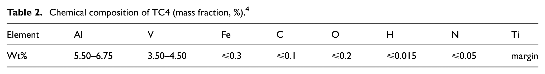
TC4 was chosen as the experiment material in this study, which has many advanced properties like good comprehensive mechanics performance, great specific strength, and low thermal conductivity, these properties extend its applications in aviation. TC4 used in the experiment is a heated and forging titanium alloy with the tested hardness of 33–35 HR. The microstructure is shown in Figure 1, which consists of equiaxed α phase and β-transformed phase. Its main chemical compositions and mechanical properties are shown in Tables 2 and 3, respectively.

The microstructure of TC4.
Chemical composition of TC4 (mass fraction, %). 4
Mechanical properties at normal temperature of TC4. 4

Samples preparation
Two cuboid samples with the size 120 mm × 60 mm × 15 mm were prepared, which were made as a thermocouple to measure milling temperature and milling force. Other samples with the size 120 mm × 60 mm × 60 mm were prepared for tool wear investigation.
Cutting tools
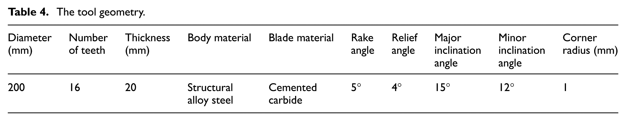
Staggered teeth disk cutter with three cutting edges was applied, which was produced by Zhuzhou cemented carbide works, as shown in Figure 2. Two inserts were used for all experiments in this article, one was for milling force and milling temperature measurement and another was for tool wear analysis. Titanium alloy is a difficult-to-machine material, thus the tool materials are crucial for maintaining its life circle and improving the quality of parts. Related study 19 showed that the cemented carbide tool was most suitable for processing titanium alloy. As a result, an uncoated cemented carbide tool (YG6) was chosen in present experiments, which is composed of 96 wt% tungsten carbide with 4 wt% cobalt.9,10 The tool geometry is shown in Table 4.

Disk cutter.
The tool geometry.
Machining conditions
XH716 VMC was utilized as the milling platform with climb milling. In order to enhance the tool life, emulsion was used as cooling liquid. It is important to note that the disk milling grooving for blisk is a new approach; there are no adequate relevant cutting parameters for reference. Based on our previous works and the device’s limitation, the spindle speed was set as 100 r/min. Depth of cut was set as 10 mm according to the depth of blisk’s tunnel. Feed speed was set as 80 mm/min because the vibration of machine and tool wear will be aggravated if exceeding this value.
Experimental methods
A semi-artificial thermocouple composed by TC4 (φ0.3 mm) and constantan wire (φ0.3 mm) was used to measure the milling temperature, as shown in Figure 3. To prepare a TC4-constantan thermocouple, two pieces of TC4 samples of 120 mm × 60 mm × 15 mm were machined first, and the constantan wires of 100 mm totally in length with 70 mm flatted part forced by a hammer was produced, another 60 mm with 30 mm flatted part was prepared; a layer of glue was coated on the specified surface of each TC4 sample, with mica plates stuck subsequently to tightly hold the wires and form the insulating layer; TC4 samples were then bonded to further clamp for 8 h more with the help of a vice in room temperature before the functional evaluation of this prepared semi-artificial thermocouple.

Semi-artificial thermocouple.
The measurement system of milling temperature was shown in Figure 4, which was composed of a semi-artificial TC4-constantan thermocouple, an A11S11 signal disposal module, a UA305 high-speed USB data collector, and a computer.

Measurement system of milling temperature.
Milling force was measured by a piezoelectric dynamometer. The measurement system of the milling force was composed of a Kistler 9225B dynamic piezoelectric dynamometer and a Kistler 5017A charge amplifier, which were connected to a computer, as shown in Figure 5. Milling forces in three directions were represented as Fx—perpendicular to the tool feed direction, Fy—parallel to the tool feed direction, and Fz—parallel to the milling axis, respectively, as shown in Figure 5.
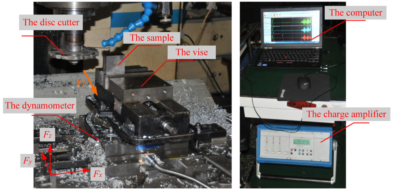
Measurement system of milling force.
The average flank wear (VB) was used to evaluate tool wear, which was measured by the automatic tool analyzer. A controlled interrupted milling length of 60 mm was carried out aiming to measure the growth of VB. The measurement of VB was conducted with three replicates as the results. It is agreed that the disk cutter is out of operation when VB is up to the special value (0.3 mm), meanwhile the worn teeth exceeds three in total, then the experiments are stopped. Afterward, the worn disk cutter’s blade was cut down using linear cutting machine and washed in alcohol, followed by ultrasonic cleaning with acetone. Finally, the damage morphologies of washed blade were detected using SEM, and its wear mechanisms were assessed by X-ray EDS. 10
Results and discussion
The milling performance analysis
In cutting temperature experiment, thermoelectric potential can be obtained, but not temperature signal, as shown in Figure 6. A calibration must be made before experiment. A relationship between the temperature and thermoelectric potential can be reflected by calibration curve and fitted equation, as shown in Figure 7. The two calibration curves represent up and down process, respectively, and the up curve is chosen as conversion curve because milling temperature is an incremental process. Figure 6 shows the thermoelectric potential when VB is zero. Choosing the maximum value from them, which is plugged into the Tup equation, the actual milling temperature is calculated with the assistance of it. The milling temperature converted is about 960°C, which increases as the machining progresses. Such a high temperature is bound to have an adverse effect on tool wear.

Measurement wave of potential signal.

Calibration curve of TC4-constantan thermocouple.
The wave of milling force is shown in Figure 8 when VB is zero. Mean force by averaging 50 peak values of continuous transient milling force is used as the experiment result, the results of Fx, Fy, and Fz are about 1906, 1376 and 545 N, respectively. It is illustrated that milling force is decreased or increased periodically when disk cutter exits and enters the workpiece. The uneven milling force will give rise to the tool vibration and then intensify the tool’s fatigue failure. Beyond that, the tool wear is also affected by the big tool diameter and more tooth (Figure 1). In addition, since Fx is much higher than other two forces, a conclusion can be made that Fx has a leading role on tool wear, the controlling of Fx is very important in machining process.
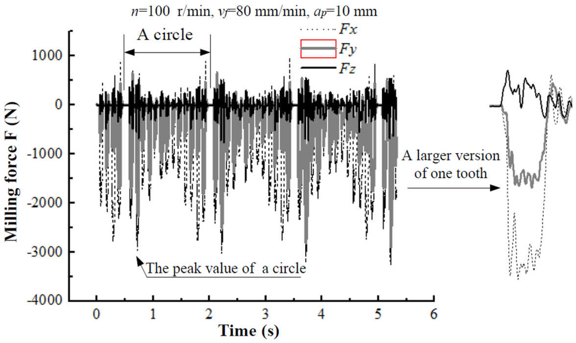
Measurement wave of milling force.
The tool life
The tool life curve is plotted according to the growth of VB, as shown in Figure 9. Horizontal axis is indicated with milling time and milling length simultaneously. It can be known from the curve that there are three stages: initial wear stage, normal wear stage, and severe wear stage. The cutting edge is sharp during initial wear stage (0–9 min), the contact area between flank face and machining surface is small, and the pressure is large, resulting in accelerated wear of cutter disk. Then, a narrow faceted pebble appears on flank face, the pressure decreases, the growth of flank wear becomes stable, and it is operational use time of disk cutter from 9 to 42 min, namely, normal wear stage. After normal wear stage, the cutting edge becomes blunt, milling force enhances, and milling temperature increases as the machining progresses, so disk cutter enters severe wear stage, which sustains about 5 min. During this stage, the growth of flank wear is rapid, not only the wastage of tool material is serious but also the quality of parts is affected greatly.

The tool life curve of disk cutter.
It can be known from the analysis of milling length, disk cutter is out of operation after milling length is up to 960 mm, namely, after milling 16–17 times. For an example of five-stage compressor blisk of a certain type aircraft engine with more than 80 tunnels, material removal volume of one tunnel is about 10,560 mm. 3 The material removal volume equals 10 tunnels’ volume when the milling length reaches 960 mm. In general, the cemented carbide tool can be reused for five times after grinding, in that way, only 50 tunnels can be finished during the service life of disk cutter. Therefore, the disk cutter still needs to be changed with high-frequency for the blisk processing. In order to improve the efficiency of disk milling grooving for blisk, the tool life must be enhanced greatly.
The wear morphologies
Delamination
Delamination of disk cutter is observed in early machining stage, as shown in Figure 10(a). Since the cemented carbide is a hard and crisp material, the crack and flaw may be existed in the surface structure before using. 6 In addition, the residual stress on the surface of tool also cannot be neglected, which is generated by pre-welding and pre-grinding. 1 As the tool emerges to the alternate milling forces in disk-milling grooving process, the defects will be expanded, then lead to delamination with the shape of flake easily.

The tool damage morphologies: (a) Delamination, (b) Thermal crack, (c) Plastic deformation, and (d) Tipping.
Thermal crack
Thermal crack is indicated after machining in Figure 10(b), which is generally found for the cutting edges around the keyway. Disk milling is a typical intermittent cutting process, and high-frequency mechanical shock and thermal shock are produced when cutting edge exits and enters the workpiece circularly (Figure 8). Moreover, the shock is powerful because of bigger tool diameter (Figure 2; 200 mm). Milling force and milling temperature are then greatly increased after the disk cutter is worn. 10 The cutting edge sustains high-frequency mechanical stress and thermal stress alternately, so expands from the heat and contracts from the cold continually. The thermal crack perpendicular to the cutting edge is produced when thermal stress reaches the fatigue strength limit.4,16 The shocks that the cutting edges around the keyway endure are stronger than the rest, which is due to that the installation accuracy between key and keyway is poor, so thermal crack in this potions occurs easily compared to other sections.
Plastic deformation
Plastic deformation can be seen in Figure 10(c) when milling temperature is up to some degree during disk-milling grooving process. The reason for plastic deformation is due to the ability of the workpiece and the tool to maintain its strength at high temperature. It is known from Figures 6 and 7 that milling temperature is up to 960°C when VB is zero, which increases as the machining progresses. On one hand, the O and N elements in air are easily absorbed by titanium alloy due to its high chemical activity at such a high temperature, so the surface of titanium alloy becomes hard and fragile. On the contrary, the hardness of tool may be decreased after oxidation wear and diffusion wear. 6 As a result, the cutting edge is squeezed when the cyclic mechanical stress is impacted on the tool, so the plastic deformation is produced. It is reported 15 that the grain size and the content of Co could also contribute to the plastic deformation.
Tipping
Tipping is found after machining in Figure 10(d). Similarly, the phenomenon of tipping is serious for the cutting edges around the keyway. The first reason giving rise to this phenomenon is the large pressure between cuttings and rake face. Because the deformation coefficient of titanium alloy is small, the cuttings would scroll upward when they are forced to leave cutting edge, which reduces the contact area and improves the pressure at rake face. Moreover, the milling force on the contact surface is greatly enhanced because the friction coefficient is large between titanium alloy and the tool. The tipping phenomenon will take place when the alternating stress impacted on the tool exceeds its fatigue strength limit. 10 For disk milling application, the vibration of tool is inevitable because disk cutter has a large diameter (200 mm) with a number of 16 teeth. Moreover, the cutting edge of each cutter tooth is not on the same circumference, so uneven force distribution in each single tooth is existed. In addition, cutting edges of each two teeth are staggered, the milling force from different cutter tooth is also different. The serious mechanical shock caused by drastic vibration may also contribute to edge tipping.
Tool wear mechanism
Adhesion
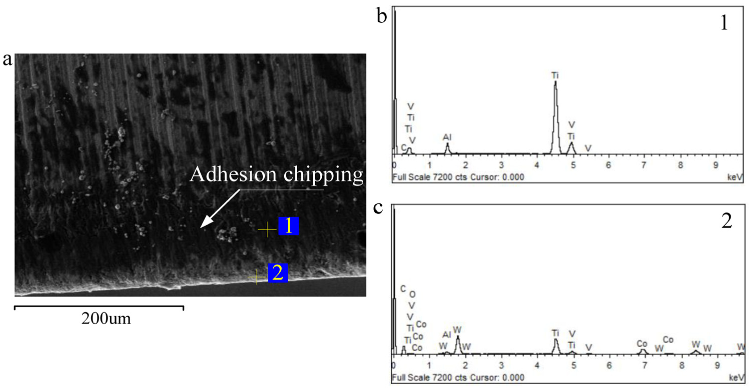
The flank face and rake face of major cutting edge and minor cutting edge are selected to analyze adhesion wear. Energy spectrum analysis on black substance attached on the cutting edge (point 1) demonstrates that only the elements of TC4 (Ti, Al, and V) are found, as shown in Figures 11–14, which is an evidence of adhesion wear. Titanium alloy is easily adhered on the surface of the cutter at high cutting temperature because of its high chemical activity to the cemented carbide. The research 12 shows that the chemical reaction between Ti element of TC4 and WC particles from the tool material is quite easily triggered when milling temperature reaches 727°C. The milling temperature is about 960°C in present experiment, which is bigger than 727°C. Moreover, the content of Ti and WC is large, so a large number of reactants are produced. The new reactants (W and TiC) weaken the strength of surface layer of cutter.5,10 The weakened layer is readily fell off from the cutter surface with the effect of circular mechanical shock, resulting in the loss of particles from cutter surface. This phenomenon is continuous when old bonding layers peel off and new adhered layer forms, which accelerates the tool wear.4,10

SEM micrograph of (a) the worn flank face of main cutting edge, (b) EDS spectrum of point 1, and (c) EDS spectrum of point 2.

SEM micrograph of (a) the worn rake face of main cutting edge, (b) EDS spectrum of point 1, and (c) EDS spectrum of point 2.

SEM micrograph of (a) the worn flank face of minor cutting edge, (b) EDS spectrum of point 1, and (c) EDS spectrum of point 2.
SEM micrograph of (a) the worn flank face of minor cutting edge, (b) EDS spectrum of point 1, and (c) EDS spectrum of point 2.
Oxidation
The research 9 shows that some soft oxides (WO2, WO3, CoO, and Co3O4) can be formed when milling temperature is up to 727°C because the chemical reaction between O element and the elements (W and Co) from tool material 10 is triggered. The milling temperature is 960°C in disk-milling grooving experiment, which is higher than 727°C, so the surface material of tool is bound to be oxidized and then be taken away accompanied by the peeling off of these oxides in milling process. The zones of peeling off would be replaced by a new bonding layer in following milling process, the new bonding layer is peeled off, then the new peeling layer is produced again, so the oxidation wear is accelerated such and such.5,12
Energy spectrum analysis can also be used to study oxidation wear. The element O is found at the cutter edge (point 2), shown in Figures 11(c)–14(c), which can be taken as the proof of oxidation wear. Since element O is not discovered in bonding layer (point 1), shown in Figures 11(b)–14(b), it proves that the oxidation does not happen on titanium alloy, but only on tool materials at high temperature. The automatic content of oxygen from EDS results is plotted in Figure 15. It is shown that oxidation wear of major cutting edge at rake face is the worst with the oxygen content of 32.74% compared to flank face of 24.76%. The oxygen content of minor cutting edge in rake face and flank face are 21.47% and 14.45%, respectively. The distinction of oxidation degree between major and minor cutting edge is mainly based on the different cutting conditions. It is known from Figure 8 that Fx is bigger than other two forces, namely, the major cutting edge endures a higher milling force. In addition, most of the materials are removed mainly by major cutting edge during disk-milling grooving process, therefore milling temperature around major cutting edge must be higher than minor cutting edge. Considering above two factors, major cutting edges are easily oxidized. The difference of oxygen content between rake face and flank face is also induced by temperature. It is due to that a higher temperature is generated on rake face, 10 as a result of more serious oxidation wear.

Automatic content of oxygen from EDS result.
Diffusion
The research conducted by Deng et al. 12 indicates that the inter-diffusion takes place between tool material and titanium alloy when temperature reaches 400°C, the degree of inter-diffusion is enhanced with an increase in temperature. The tool material diffusing into titanium alloy is peeled off under continuous shocks, which leads to the losses of tool element. The milling temperature is about 960°C when VB is zero in the present experiment, which is increased with tool wear. Such a high temperature certainly will induce the inter-diffusion when the cuttings stick to the cutting edge in disk-milling grooving process. Known from the above analysis, titanium alloy is easily adhered on the cutting edge during disk-milling grooving process. Although the wear mechanism between adhesion wear and diffusion wear is different, both phenomena occur simultaneously and influence each other.12,13 So the study on diffusion wear has an important meaning for the application of disk cutter.
It can be seen from Figures 11(c)–14(c) that there are not only the tool elements (W, C, and Co) but also titanium alloy element (Ti) on the cutting edges, which brings difficulties to distinguish them caused by adhesion wear or diffusion wear only by EDS analysis. In order to analyze the tool’s diffusion wear, a method is adopted, as shown in Figure 16(a): several points are selected on the zone of diffusion interface between tool material and the attached titanium alloy, and each point is analyzed quantitatively by EDS. Then the content of a certain element from different points is obtained as a function of the distance of selected points to plot the diffusion curve. Since the main element of TC4 is Ti, the tool material (YG6) is composed of WC (96%) and Co (4%), the diffusion degree of the elements Ti, W, C, and Co is paid attention in this article. The flank face of main cutting edge has a leading role during disk-milling grooving process, which is selected to analyze diffusion wear. The diffusion curves of each element are plotted in Figure 16(b).

Diffusion analysis of the worn disk cutter: (a) SEM micrograph of the worn tool and (b) diffusion curves along the interface.
It is shown in Figure 16(b) that the diffusion depth of W is about 3.5 µm, the Co and C are both about 1.5 µm, and the depth of Ti is 1 µm. A fact can be deduced that the element Ti is difficult to diffuse into the tool material. The concentration value of element W and Ti is a half of its initial concentration at the diffusion interface. However, the elements C and Co are not confirmed to the law, which is due to that the contents of them are little and uneven distribution. Although the elements W and C both belong to the tool material, the diffusion depth of element C is smaller than the element W. It is due to that a chemical reaction may set off when the element C encounters the element Ti, and then the reactant TiC is produced. The diffusion velocity of element C is prevented by this phenomenon, so the diffusion depth is little. 13 Likewise, the diffusion depth of Co is also little, but the loss of element Co is serious and the content of element Co is less than half of the normal value at diffusion interface. The element Co is a binder,12,13 so the binding power between WC particles and the tool is decreased due to the wastage of element Co, the strength and toughness of the tool are reduced, and the machinability is weakened.
Conclusion
It is known from the tool life curve that disk cutter is out of operation after 48 min. For an example of five-stage compressor blisk of a certain type aircraft engine with more than 80 tunnels, disk cutter can only remove about 50 tunnels’ roughing volume after five times grinding, so the tool life still need to be greatly enhanced.
For disk milling grooving, the bigger tool diameter and uneven milling force induce fatigue failure. The main damage morphologies of disk cutter are delamination, thermal fatigue crack, plastic deformation, and tipping. Thermal crack and tipping are easily found at the cutting edges around the keyway, which is due to poor installation accuracy between the key and keyway.
High milling temperature in disk-milling grooving process is a main reason for tool wear. The corresponding wear mechanisms are the synergistic interaction among adhesion wear, oxidation wear, and diffusion wear.
The thermal crack and tipping can be avoided by optimization structure of disk cutter. The wear rate of disk cutter can be reduced by decreasing milling temperature or optimizing technological parameters.
Footnotes
Academic Editor: M Ravichandran
Declaration of conflicting interests
The author(s) declared no potential conflicts of interest with respect to the research, authorship, and/or publication of this article.
Funding
The author(s) disclosed receipt of the following financial support for the research, authorship, and/or publication of this article: This work was supported by the National Numerical Control Major Projects Foundation of China (Grant No.2013ZX04001081), the National Natural Science Foundation of China (Grant No.50975237 and 51005184), and National Aerospace Science Foundation of China (Grant No.2013ZE53060).