
Abstract
An analytical solution for vertical vibrations of a simply supported bridge under the action of moving loads is derived and validated. The effect of bridge frequency, span length and vehicle length on the amplification factor of mid-span displacement is discussed using theoretical formulas and numerical results. The study finds and validates that the maximum bridge amplification factor is function of the length ratio of the bridge-to-vehicle. When the speed of the vehicle is high enough to cause bridge resonance, the maximum amplification factor of the bridge is a certain value, which has no relation to bridge’s frequency. The frequency only affects the speed the maximum amplification factor appears. The changes in the amplification factor are analyzed with the bridge-to-vehicle length ratio, which provides a basis for the selection of bridge span length. A simplified, practical formula for calculating the amplification factor is given. The presented results will be particularly useful for railway bridge preliminary design for high-speed trains and assessment of the expected maximum vibration levels.
Keywords
Introduction
In China’s railway construction, there are nowadays over 50,000 simply supported bridges, accounting for about 95% of the bridges in China, which has systemized the span commonly used in China’s unique high-speed railway. Such a large amount of simply supported bridges will present new challenges to the relevant standardized design. During bridge and culvert design, the amplification factor is one of the most important design parameters, and has, therefore, been extensively studied in the past. The following is a brief overview of the practices adopted in railway bridge design in various countries and by a major international organization.
International Union of Railways (UIC)
The limit state design method is adopted for the design of railway bridges by the UIC, and the design amplification factors are determined using train load diagrams. The research institutions organized within the UIC have conducted a large number of bridge dynamic analyses for various types of trains to determine the vertical fundamental frequency limits of simply supported bridges with different span lengths. If the fundamental frequency of the bridge meets the specified requirements, further calculations can be carried out using Load Model 71 diagram and amplification factors stipulated by the UIC. The UIC design amplification factor formula has no physical meaning and is a function of span or loaded length. 1
Japan
The limit state design method is adopted in the design of railway bridges in Japan, and different types of load diagrams are adopted for different railways. For the lines carrying different vehicles, variable amplification factors are considered, but without differentiating between the design amplification factor and operation amplification factor. The amplification factors mainly consider the effect of moving loads and the influence of track and wheel irregularities. 2
The United States
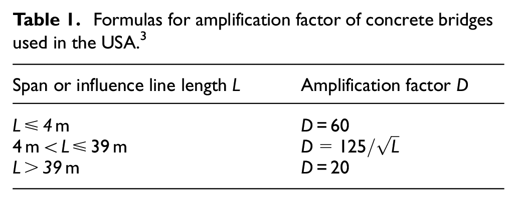
The allowable stress method is used in American railway bridge design. The amplification factors for bridge and culvert structures are expressed as percentages of the vertical static live load, which is a function of span length. 3 The simple formulas of the amplification factor for concrete bridges are shown in Table 1.
Formulas for amplification factor of concrete bridges used in the USA. 3
Australia
Australian bridges are designed according to the limit state method, and the vertical load effects of the train loads are calculated as “D × Partial coefficient of load × Train load.” Ballasted and ballastless track bridges are no longer differentiated. When calculating the dynamic effects on the bending moments, the amplification factor is calculated as follows 4 :

China
The amplification factors for high-speed and intercity railways are mainly formulated with reference to the UIC specifications, and their formulas have no physical meaning. The calculation process of the amplification factor comprises three main stages. In the first stage, the amplification factors are determined based on the shear force and the bending moment. In the second stage, the same calculation formula is adopted for the shear force and bending moment amplification factors, which is the same as that of the careful maintenance line in the latest UIC regulations. In the third stage, the amplification factor is reduced for culverts and structures with filling on top, which is based on experimental data. 5
Due to the differences in trains used in different countries, the adopted load patterns and amplification factors vary. The railway design codes generally adopt two methods for modeling train loads. The first method uses the vehicle axle loads and wheelbase, such as the Japanese N, P, and H loads, urban rail transit subway Model A and B vehicles, and intercity railway load in China. 5 The other method uses train load diagram, such as the United States Cooper E load, 3 the UIC Load Model 71, 1 and the Chinese ZK, ZC, ZKH, and ZH load diagrams. 5 The international methods for establishing the amplification factors can generally be divided into three categories: (1) The UIC formula is essentially an adjustment coefficient for the design live load with no physical meaning. The amplification factor can be obtained by substituting the span length into the formula. (2) The amplification factors with physical meaning used in Japan are calculated according to the span length, fundamental frequency, and other parameters, and compared to the amplification factor check chart. (3) The American amplification factor formula is fitted to measured data and related to the span length. It has a physical meaning.
When the amplification factor is calculated by the train load diagram method, the resulting design load value can be large. For economic considerations, the value of the amplification factor is relatively small, but ensures the bridge structure can still meet the safety requirements. However, when the real train axle load is assumed, and the amplification factor is calculated by a train load diagram method, the predicted dynamic effects on the bridge will be less than the actual, and the design will be nonconservative. Therefore, it is suggested that the real axle load be adopted in the train load model when calculating the amplification factor.
However, due to the complexity of the influencing factors, designers often need to devote significant time and energy to calculate and analyze train-bridge dynamics. The existing research often focuses on the calculation of train derailment coefficient, wheel load reduction rate, and other safety indicators, as well as vehicle body acceleration, Sperling index, and other passenger comfort indices.6–10 However, there are relatively few studies on the factors influencing bridge vibrations, especially the dimensionless parameters, and the conclusions obtained are often only applicable to specific conditions.11–15 In Yang et al.’s 16 research, his numerical verification gives results of the bridge without damping, and does not give the expression of amplification factor in resonance state, which can’t be used to directly guide the design. Museros et al.’s 17 research only gives the resonance or vibration elimination of the bridge when the bridge vehicle length ratio is a specific value, and does not comprehensively analyze the amplification factor. He mainly focused on the analysis of the maximum acceleration caused by resonance and proposed a new approximate formula for estimating the maximum acceleration caused by resonance of simply supported beam bridge, but did not give the formula of the maximum amplification factor. The code of UIC 776-1 points out in article 2.4.2.1 that the amplification factor is not applicable to the resonance between vehicles and bridges. 18
In bridge design, the amplification factors in existing codes such as China and Europe are proposed based on load generalization methods such as ZK load and load model 71. In this paper, the generalization method for the train axle load is investigated, and a large number of studies show that the moving loads model has wide applicability. The analytical solution of dynamic response of simply supported beam bridge is derived in this paper. The factors affecting the dynamic behavior are analyzed theoretically. The fitting formula of amplification factor based on train load model are given, which has a good reference value for bridge design in the future.
Theoretical analysis
Theoretical solution for bridge displacements under moving load
In this section, based on the actual train axle load and wheelbase model, the vertical displacement of the simply supported beam under the action of the moving loads is deduced.
A typical 32-m long simply supported box girder has a mass of more than 1100 tons, while the mass of the train passing over a single span is about 60 tons. It can be seen that the train mass is far less than the mass of the simply supported beam. Following the UIC776-2 specification, 1 the train can therefore be simplified to a moving force sequence, as shown in Figure 1, where the full length of single vehicle is LV, distance between bogie centers is LC, and the fixed wheelbase of the wheelset is LW. The axle loads are numbered Pkj (k = 1, 2, 3, … Nv; j = 1, 2, 3, 4) beginning where the train starts. Subscript k represents the vehicle number, and j represents the wheelset number in that vehicles. And suppose the train speed is V.

Analytical model of train axle loads crossing bridge arranged according to actual axle spacing.
There is a delay between the times at which each set of axle forces arrives at a certain point. The time of the first moving load of the k-th vehicle entering the bridge is tk1, where
The basic assumptions of this paper is as follows:
Ignoring the stiffness, mass and damping of the train suspension system, the train is simplified as moving loads. And the longitudinal connection between each vehicle is not considered. The loads are moving at a constant speed.
The simply supported bridge girder has a constant cross-section and uniform mass distribution per unit length.
The bridge adopts Rayleigh damping, the damping ratio of each order is constant, and the damping matrix is solved by the first two vertical frequencies of the bridge
The material of the beam is linear elastic, in other words, compared with the size of beam, displacement is very small.
The beam is considered as a standard Euler beam. Without considering the piers, the bearings are considered as the ideal bearings, which are arranged at the beam end, and do not move.
Only the vertical vibration of the bridge is considered.
Based on the above assumptions, the differential equation of motion for the simply supported bridge girder under moving constant loads can be written as follows16–28:
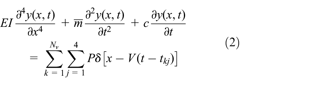
where δ is the Dirac delta function, and c is the damping coefficient. For simply supported beams, the boundary conditions are y(0, t) = 0, y(L, t) = 0.
Because the above formula is a partial differential equation, it can be solved by the method of separation of variables
The basic principle of the mode decomposition method is to transform the geometric coordinates of the structure into mode coordinates or generalized coordinates. For a unique continuum, its expression is equation (3).

where
The mode shape components of any deformation of the structure can be obtained by using the orthogonal properties of the mode shapes. For a beam with uniform cross-sectional properties, in order to calculate the contribution of the nth mode shape to the displacement y(x, t), multiply both sides of equation (3) by

Due to the orthogonality of the mode shapes, when

According to the above principle, the vibration equation of the simply supported beam is solved, and the equation (3) is substituted into the equation (2), resulting in equation (6).

Multiply each term of the above equation by the nth-order mode shape function

For a simply supported beam of a uniform cross section, the mode shapes are as follows:

At this time


Obtained after integration

Where

where
This is a linear differential equation with constant coefficients, and it is obvious that the vibration mode equations of each order are independent of each other. Through Duhamel integral, its particulars solution can be obtained as follows:

where
Substituting equation (12) into equation (11) gives:
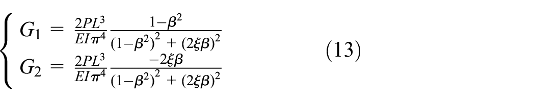
where
In order to solve the supplementary solution of equation (11), consider the homogeneous equation with the load term 0 on the right of the equation, and let the form of the solution be

The characteristic equation is equation (15).

By introducing symbol

Bringing equation (16) into (14), the expression for the vibration response of the low damping system is obtained as:

By introducing Euler equation

Now, substitute equation(18) into equation (11), and initial conditions

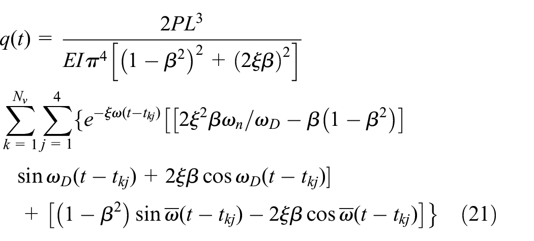
The general solution of the damped system under the action of the moving load sequence consists of the complementary solution and the particular solution, namely:

When only the fundamental frequency of the bridge is considered, the general solution to the equation of motion of a simply supported beam under the action of a moving load sequence in the generalized coordinates is as follows:
Thus, the analytical solution for the vertical vibration displacements of a simply supported bridge considering only the first mode of vibration can be written as follows:

Influence of bridge natural frequency on amplification factor
This section will use the bridge displacement equation derived above to deduce the amplification factor of bridge displacement.
To simplify the analysis, the rear bogie of the front vehicle and the front bogie of the rear vehicle are simplified into a concentrated load, and the load spacing is the length of one vehicle
Suppose the distance between two adjacent moving loads is Lv. For the mid-span of the bridge, x = L/2, the formula for its displacements becomes as follows:

Because damping is usually small,

where
When studying the amplification factor of a bridge, the maximum dynamic deflection of the bridge is an important parameter. It is known that when a moving load sequence composed of a series of axle loads passes over a bridge, each load will cause a transient response due to periodic excitation. The response amplitude will be increase as the number of passing loads increases, causing the bridge to resonate, at which time its dynamic response will be maximum. Therefore, the velocity at the resonance moment is directly introduced into the formula for derivation, and the maximum displacement response of the bridge is obtained. The resonance condition is a follows16,17,28,29,30:

When i = 1, the first resonance occurs, the resonance effect is the strongest, and the dynamic response is the largest.
Consider the first term of the summation in equation (24) when N moving loads pass over the bridge, as shown in equation (26).

From the resonance condition, equation (25):
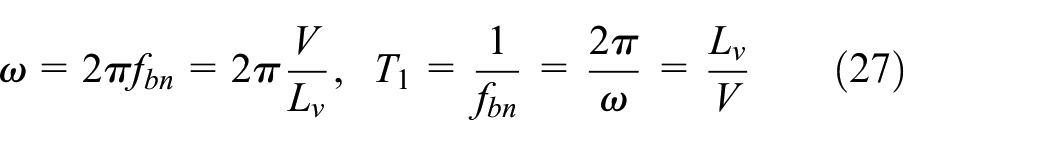
where T1 is the apparent period of the load sequence.
Insert equation (27) into equation (26) to obtain the following:

Using the trigonometric function relationship, equation (28) can be written as equation (29).

Because

Because
Therefore,
In equation (30), when
At this time,

Where
where constant R is such that t = R × T1. Substitute the constant R into equation (28) to obtain equation (32).

The second term of equation (24) is now analyzed for the resonance condition.
Further, there is a relationship between T2 and T1, that is,

Substitute

Then, the maximum dynamic displacement from equation (24) can be written as follows:

The maximum static deflection of a simply supported beam under the static application of the load sequence can be expressed as follows:

where

Because
Numerical verification
The maximum amplification factor of a bridge derived in Section 2.2, is independent of the bridge frequency. In this section, an example is used to further illuminate that conclusion.
Vehicle parameters
At present, high-speed trains are generally eight vehicles, so the paper is based on eight vehicles, similar to that shown in Figure 1, was simplified to four moving loads per vehicle P = 204 kN. The total length of a single vehicle was LV = 25 m, the bogie center distance LC = 17.5 m, and the wheelset fixed wheelbase LW = 2.5 m.
Bridge parameters
In this section, the bridge parameters are mainly introduced, especially the selection of bridge mass is discussed. Considering a 32-m long simply supported beam, whose fundamental frequency satisfies the lower limit specified in Article 5.2.5, Paragraph 1 of “Code for Design on Railway Bridges and Culvert TB10002-2017” (see Table 2), and take 1–3 times the base frequency, and calculate the interval 0.1 times. The damping ratio was assumed as 0.01 following the suggestions in UIC, 1 Jehel, 31 and Cruz and Miranda. 32
Lower limit of fundamental frequency of railway bridges.

After the fundamental bridge frequency is decided, the stiffness and mass of the bridge need to be determined. However, because frequency, stiffness, and mass are related, only one of the two latter needs to be selected. We study here a case when the span length of the bridge is known and the fundamental frequency of the beam is fixed, while the relationship between the amplification factor and the mass of the beam is analyzed. The theoretical derivations are as follows:
Case 1: The mass matrix of the beam is

Case 2: The mass matrix of the beam is γ
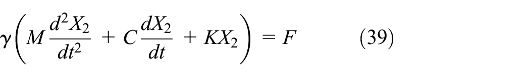
Therefore, the complex frequency response function H1 of Case 1 and the complex frequency response function H2 of Case 2 satisfy H1 = γH2.
If the quasi-static load time history of the bridge is F0 and the dynamic load time history velocity is Fv, then the quasi-static response time histories of Cases 1 and 2 satisfy
The amplification factor is
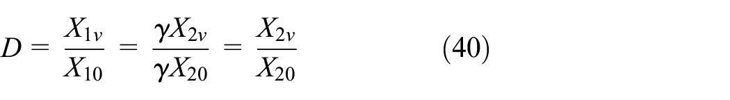
It is independent of the mass of the beam when the bridge span length is fixed and its fundamental frequency is known. Therefore, in the modeling process, a reasonable choice of mass is sufficient.
Influence of bridge frequency on amplification factor
In this section, the above train and bridge parameters were selected, and train velocities from 50 to 600 km/h were considered. The changes in the bridge amplification factor at the mid-span with velocity for different bridge fundamental frequencies are shown in Figure 2.

Influence of bridge stiffness on amplification factor.
From the figure, the maximum amplification factor of the bridge was about 2.9. Therefore, it was demonstrated that the maximum amplification factor for the 32-m simply supported beam occurs when the bridge resonates, and has a fixed value that does not change with the change in the bridge frequency.
In order to verify that simply supported bridges with different span lengths have the same property, a variety of span lengths ranging from 12 to 56 m were analyzed. Due to lack of space, individual charts are omitted, but it was again observed that the maximum amplification factor of the bridge does not change with the frequency of the bridge under the resonance condition.
According to the above examples, when the train passes over a bridge at a resonance velocity at a certain frequency, the amplification factor of the mid-span displacements reaches its maximum value. As the natural frequency of the bridge increases, its critical resonance velocity also increases, but its amplification factor remains unchanged.
Influence of bridge-to-vehicle length ratio on amplification factor
It was concluded in Section 3 that even if the natural frequency of the bridge changes, the maximum amplification factor under resonance condition does not. Therefore, when studying the amplification factors of different vehicle and bridge span lengths, the frequency of the bridge can be taken according to Table 2.
Let the bridge-vehicle length ratio be denoted as α, that is, α = L /Lv. Consider α from 0.5 to 3 with an increment of 0.1. The length of the bridge varied from 6 to 75 m.
Since the length of a single section is about 12 m for a freight train, about 20 m for an inter-city train, and about 25 m for a high-speed train, the relationship between the bridge mid-span amplification factor and the dimensionless parameter α for these three types of vehicles were analyzed, and the results are shown in Figure 3.16,33–36

Influence of dimensionless parameter α on amplification factor.
It can be seen from the above figure that the maximum amplification factor of the bridge is only determined by α, and there are obvious crests and troughs in the plot. We also observe here that the value of the amplification factor is similar to that in the Japanese code, both of which are larger than those in the Chinese code, indicating that the amplification factors of the two load patterns are different. The analysis shows that when the bridge-to-vehicle length ratio is near 0.5, β is about 1, that is, the vertical natural frequency of the bridge is the same or similar to the apparent excitation frequency of the load, and the amplification factor will be the largest. When α = 1.5 and 2.5 (and α = j/2, j = 7, 9,…), vibrations are suppressed, and the amplification factor of the bridge is smaller. The observed patterns can provide a basis for the selection of bridge span during design. The conclusion here is the same as that in Yang et al. 16 and Savin 36 which also proves the correctness of the above derivation.
For example, 32-m long simply supported bridges are often used in the construction of high-speed railways in China, while the length of the vehicles is about 25 m,that is, α = 1.28. It can be seen from Figure 3 that in this case the amplification factor is small, and the bridge span length is suitable. The recent 40-m long simply supported bridges 37 have α = 1.6, which is located near a minimum of amplification factor curve, and thus this span length is also suitable.
With the development of society and the deepening of theoretical research, the train speed will continue to improve in the future, and combined with economic factors, the stiffness of the bridge will be optimized, which greatly enhances the possibility of resonance speed within the operation range. Therefore, it is of great significance to put forward the value of the maximum amplification factor. In order to assist bridge designers and provide a reference for future practical applications, the curve in Figure 3 was approximated as shown in Table 3.
Amplification factor formulas.

Conclusions
The paper proposes a model for train axle load and wheelbase, a formula of the amplification factor for train loads running through a simply supported bridge has been proposed.
For different vehicle and bridge span lengths, near resonant velocity, the maximum amplification factor of the bridge is determined by the non-dimensional bridge-to-vehicle length ratio, and no relation to the bridge frequency. However, the maximum amplification factor of certain train speed range can be controlled by the bridge frequency. The relation between bridge amplification factor and bridge-to-vehicle length ratio was calculated, the formula of designing amplification factor for bridge are proposed, which is of great significance for higher speed trains and more economical bridges in the future.
Footnotes
Appendix
Acknowledgements
Handling Editor: Chenhui Liang
Declaration of conflicting interests
The author(s) declared no potential conflicts of interest with respect to the research, authorship, and/or publication of this article.
Funding
The author(s) disclosed receipt of the following financial support for the research, authorship, and/or publication of this article: The research described in this paper was financially supported by the National Natural Science Foundation of China (52178101) and the National Natural Science Foundation of China “International (Regional) Cooperation and Exchange Project” (51720105005).
Data availability
All the raw data used to support the findings of this study are included within the article and any underlying research materials related to the paper (e.g. data, samples or models) can be accessed.