
Abstract
The plastic-damage factor of concrete structures is important for structural load-capacity assessment, while it has not been determined properly. In this article, two methods perspectively based on the strain equivalent principle and Sidiroff energy equivalent principle are proposed to determine the plastic-damage factor of the concrete uniaxial constitutive relation in a specification. Both of them were applied to a finite element analysis model of a simply-supported beam for nonlinear load-capacity analysis. The load-capacity experiment of the beam was carried out in unison. From the comparison of the result obtained by the energy equivalent principle method coincides better with the experimental result, which suggests that the energy equivalent principle method is reasonable and applicable. Therefore, the factor could be recommended for further consideration in specification and finite element analysis calculations.
Keywords
Introduction
More and more long-span bridges have been built over the past decades.1,2 With the rapid development of finite element technology and computer industry, the large general finite element software has provided a new channel to solve some complex engineering problems, especially owning broad application prospects in the safety assessment field of the large-span bridge in service. Many bridges in the world were built a long time ago. Therefore, with the consideration of the social and economic needs for continued uses, it becomes significant to assess their current levels of integrity. 3 But the inaccuracy of the structural safety assessment will cause a series of problems, such as the too conservative design, unnecessary maintenance reinforcement, diseconomy, radicalness, and safety accidents. The existing finite element method can accurately evaluate the ultimate bearing capacity of the structure and avoid the problem mentioned above, but the premise should be that the constitutive relation of the material can be simulated accurately. For the common reinforced concrete structure, the bilinear elastic–plastic constitutive model applied to the rebar has basically reached a consensus in academic circles.4–6 However, how to reasonably combine the constitutive relation of concrete in the specification with the finite element concrete damage plasticity (CDP) model still exist disputes. That is the method to determine the reasonable value of the plastic-damage factor in CDP model. At home and abroad, two methods were adopted to calculate the plastic-damage factor of concrete, which were the strain equivalent principle (SEP) and the Sidiroff energy equivalent principle (EEP). 7 In the literature,8,9 the formula for calculating the plastic-damage factor was based on the hypothesis of strain equivalent, while it is based on the hypothesis of energy equivalent in the literature. 10 Even though the two methods could be achieved, which is more reasonable still need to be discussed and verified. Based on the situation, two methods were adopted to calculate plastic-damage factors of concrete. Then, the differences between the damage factors estimated by two methods were analyzed. What’s more, the test model of the reinforced concrete simply-supported beam was analyzed by involving a complete nonlinear process. Meanwhile, the verification experiment was carried out only to find that the finite element analysis (FEA) result of the damage factors determined by the energy equivalence principle coincided better with the test result. Finally, the method to determine the value of plastic-damage factor accurately was proposed.
CDP model
Before concrete bearing external loads, some micro-cracks and holes which are called “damage” have existed in the concrete. In other words, the failure process is caused by the development and evolution at various scales of the cumulative damages (micro-cracks, holes, and so on). Then, the nonlinear characteristics of stress–strain are mainly resulted from the micro-cracks. 11 The stiffness degradation of concrete is often associated with plastic deformation, presenting not only the extension of micro-cracks and defects in the microscopic mechanism but also the sliding and deformation related to the mechanism of the material flow. So, the reasonable constitutive relation should be the elastic–plastic damage constitutive model reflecting two kinds of mechanism which are the elastic damage and plastic deformation. 12 In order to avoid the trouble of analyzing the microstructure of the material, it is generally considered that the concrete is a macroscopic and isotropic material so that its mechanism of deformation and failure can be studied.
The CDP model of concrete in finite element software 9 is established on the basis of the model by Lubliner et al. Combined with the isotropic tensile or compressive plasticity, this model uses isotropic elastic-damage model to simulate the inelastic behavior of concrete. 12 It depended on the assumption that the same damage existed in every direction, which is applicable to the concrete in case of arbitrary loading forces including cyclic loading. Simultaneously, not only the degradation of elastic stiffness resulting from the tensile and compressive plastic strain but also the recovery of stiffness under cyclic loading is considered.
In elastic stage, the CDP model adopts the elastic model to describe the mechanical properties of materials. After stepping into the stage of damage, the relation between the elastic modulus in the CDP model can be described as 8

where
CDP model under uniaxial cyclic loading
Under the action of uniaxial reciprocating loading, the model uses
Figure 1 shows the schematic diagram of the elastic modulus recovery in CDP model under the uniaxial cyclic loading (from tension to compression, and to tension again) when the weighting factors of tension and compression are, respectively, described as

Schematic diagram of the concrete elastic modulus recovery under tension—compression stress transformation.
CDP model under single uniaxial tension/compression
As to the tensile stress–strain curve of concrete, the data which exceed the range of the elastic part will be entered into the finite element software with the form of

Tensile stress–strain curve of CDP model.
In Figure 2,
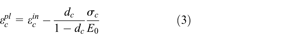
The data of tensile damage will be entered into the finite element software with the form of

If the plastic strain value
As to the compressive stress–strain curve, the data which exceed the range of the elastic part will be entered into the finite element software with the form of

Compressive stress–strain curve of CDP model.
In Figure 3,
The data of the compressive damage will be entered into the finite element software with the form of
If the plastic strain value
Formula derivation of plastic-damage factor in CDP model
Uniaxial constitutive model of concrete
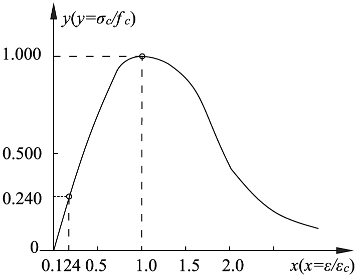
From the literature, 17 a uniaxial constitutive model of concrete is shown in Figure 3 and the exact expression is given as

where
In Figure 4,

Uniaxial stress–strain curve of concrete.
Simplification of the uniaxial constitutive model of concrete
The uniaxial constitutive relationship of concrete proposed by the literature
17
is a curve. In order to fit the CDP model in the finite element software, it is necessary to simplify the constitutive relation to a piecewise curve, in which the straight line represents the elastic stage and the curve represents the plastic stage. To describe Young’s modulus
Simplified uniaxial tensile stress–strain curves of concrete
The uniaxial tensile stress–strain curve equation of concrete can be determined by formula (5). The first part of the calculation adopts the linear elasticity while the damage occurs just after the peak value. Then, the curve is shown in Figure 5


Tensile stress–strain curve of concrete.
Simplified uniaxial compressive stress–strain curves of concrete
According to the uniaxial compressive stress–strain curve of concrete in the specification,
17
using the searching of linear interpolation, the stress point of which modulus is

where ft is the uniaxial tensile strength of concrete; εt is the peak tensile strength corresponding to ft; αt is the parameter value of the upward section in the uniaxial tensile stress–strain curve, of which calculations can be found in the specification 17 Appendix C. 2.1; fc is the uniaxial compressive strength of concrete, εc is the peak compressive strain corresponding to fc; αa and αd, respectively, indicate the parameter value of the upward section and downward section of the uniaxial tensile stress–strain curve, of which calculations can be found in the specification 17 Appendix C. 2.1.
Compressive stress–strain curve of concrete.
Calculation formula of plastic-damage factor of concrete
At present, the plastic-damage factor of concrete at home and abroad is usually determined by the strain equivalent and EEP.
Strain equivalent hypothesis
In 1971, Lematire proposed that the strain response of the damage element under the action of stress

Then, formula (8) is obtained

Energy equivalent hypothesis
According to Sidiroff EEP, 10 the elastic residual energy produced by the damaged material under stress is the same form as that of the non-damaged material as long as the stress is replaced by equivalent stress or the elastic modulus at the time of damage.
Elastic residual energy of non-damaged material

Elastic residual energy of equivalent damaged material
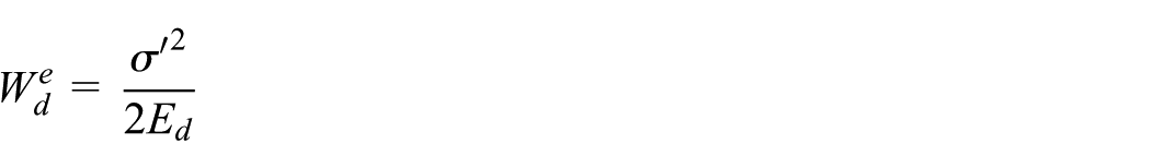
Thus, the formula below is obtained

Then

Combining equations (5) with (8), the tensile plastic-damage factor determined by the SEP is expressed as

Combining equations (5) with (9), the tensile plastic-damage factor determined by the EEP is expressed as

Similarly, combining equations (6) with (8), the compressive plastic-damage factor determined by the SEP is expressed as

Combining equations (6) with (9), the compressive plastic-damage factor determined by the energy equivalence principle is expressed as

where
In this article, C40 concrete is taken as the object of study, and the plastic-damage factor–strain curves under the uniaxial tension and compression can be obtained from equations (10)–(13), as shown in Figures 7 and 8.

Compressive damage factor–strain curve determined by strain equivalent and energy equivalent.
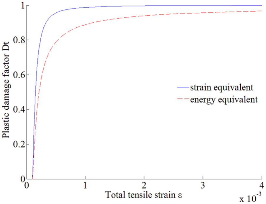
Tensile damage factor–strain curve determined by strain equivalent and energy equivalent.
From Figures 7 and 8, we can see that (1) under the uniaxial tension and compression condition, the plastic-damage factor determined by the equivalent strain principle of concrete is bigger than that by the EEP. Therefore, when strain equivalent assumption is adopted, the concrete damage of the constitutive model grows faster under the same load; (2) the curves of the tensile/compressive damage factor–strain obtained by the two methods have the same trend, and the slope of curves changes from the initiatively infinite value to nearly 0, which indicates that the damage process of concrete is developing rapidly.
Non-linear FEA and model test of RC simply-supported beam
Finite element model
The reinforced concrete (RC) simply-supported beam is based on the simply-supported plate girder bridge which is widely used in domestic highway. The 1:2 scale model is adopted as the test model with rectangular double reinforcement design, of which length is 4.98 m, section size is 230 mm × 300 mm, and concrete is C40 type. The compressive region is designed with four HRB335 steel bars with a diameter of 16 mm and the tensile region is designed with two HRB335 steel bars with a diameter of 8 mm. Meanwhile, stirrups are HRB235 steel bars with a diameter of 8 and 12 mm. The three-dimensional (3D) solid element with eight nodes in format of integral element (C3D8R) is adopted to simulate the concrete, and the linear 3D truss steel element with two nodes (T3D2) is adopted to simulate the rebar. In addition, the contact surface of steel and concrete is treated by the embedded method.16,18,19 The model of single beam is meshed using a sweep mesh control, creating 504 elements, and containing 6 degrees of freedom. The mesh converges well without analysis errors and warnings, as shown in Figure 9.

Finite element model of simply-supported beam.
Calculation parameters
The concrete plastic-damage factor can be determined by the strength grade of concrete. The C40 concrete is taken for example, of which the standard values of uniaxial compressive and tensile strength are 26.8 and 2.39 MPa, respectively. 17 Meanwhile, as for elastic modulus of cracked concrete, the secant modulus which is 22.9 × 10⁵ MPa is regarded as the initial elastic modulus of concrete and Poisson’s ratio is 0.2.
When the material steps into plasticity, the tensile and compressive plastic-damage factors in the CDP model can be obtained by formulas (10)–(13), which can be seen in Table 1.
Table of constitutive model parameters of C40 concrete in CDP model.

The design yield strength of HRB335 steel bars is

Experimental stress–strain curve of HRB335 rebar.

Ideal elastic–plastic constitutive model of steel bar.
Model test
In order to verify which method is more reasonable to determine the plastic-damage factor, the test was simultaneously carried out. The reinforcement of the test was consistent with that of the finite element model, of which the layout is shown in Figure 12. Among all the equipments, hydraulic jacks are shown in Figure 13, the pressure sensor controlling loading levels is shown in Figure 14, and the steel gaskets set in the position of bearing and loading to prevent the stress concentration through the whole process of loading are shown in Figure 15.

Sketch map of reinforcement and loading in simply-supported beam.

The hydraulic jack equipment.

The pressure sensor (50t).

The loading picture of test sample.
Some electrical measurement indicators were arranged in the mid-span of the test and the deflection information could be collected by the strain gauge. In order to ensure the accuracy of the data, the deflection of the mid-span was simultaneously observed by the precision level. Finally, the P-D curve going through the whole test process was obtained. The criterion for determining the ultimate bearing capacity of the beam through the test is that when the width of crack exceeds 2 mm, the loading cannot continue to increase. The fracture distribution of the test beam is shown in Figure 16.

Fracture distribution of the test beam.
In Figure 16, the data outside of the brackets indicate the loading level with the unit of kN, while the data in brackets indicate the width of cracks related to loading level with the unit of mm. Figure 15 shows that (1) cracks began to develop from bottom of the mid-span and the initial crack appeared as P equals to 25 kN; (2) when loading P grew up to 75 kN, the crack width developed stably, and a large amount of cracks generated with the developing tendency from the mid-span to the two ends; (3) as loading P added up to 90 kN, the width of cracks in mid-span developed rapidly but the number of cracks essentially unchanged, which indicated that the yield strength of rebar was attained; and (4) if P exceeded 90 kN, the loading failed to increase further while the plastic hinge occurred in mid-span, reaching its ultimate bearing capacity.
Comparative analysis of results
In this research, the damage constitutive model of concrete was determined using EEP at first. Then, the nonlinear finite element model which is based on the ideal elastic–plastic model of rebars (shown in Figure 11) was established. Two curves named strain equivalent (450 MPa) and strain equivalent (335 MPa) in Figure 17 were obtained. In a similar way, the other two curves named energy equivalent (450 MPa) and energy equivalent (335 MPa) in Figure 17 were gotten. The P-D curves calculated by the nonlinear FEA and measured are shown in Figure 17.

The P-D curve of FEA and model experiment of the beam.
As can be seen from Figure 17:
When the same concrete damage model and different ideal elastic–plastic models of rebar are adopted in the finite model, the limit bearing capacity of the model based on the measured strength of rebars is higher. It proves the correctness of the finite element model because the measured strength of rebars is greater than the theoretical one (as shown in Figure 11);
When the models are established by different concrete damage models and the same ideal elastic–plastic model of rebar, the P-D curves present the same tendency. The distinction is that the limit-bearing capacity determined by the EEP is greater than that by SEP of concrete in CDP model, which is due to the damage factor of the energy equivalence principle growing more slowly and absorbing more in the process of damages;
By means of combining CDP model with measured ideal yield model of rebar in the nonlinear finite element model, the P-D curve of EEP coincides better with the measured P-D curve, which not only verifies the rationality of the energy equivalent method to determine the plastic-damage factor of concrete but also shows the correctness of simplifying the ideal elastic–plastic model of rebar;
The load of the model experiment was added up to 90 kN. Then, a plastic hinge occurred in the mid-span of the beam. What determined the beam’s ultimate bearing capacity with 90 kN is that the beam counteracted the continuing loading work by the plastic deformation.
Conclusion
Through the comparative analysis of the CDP model and the uniaxial constitutive model of concrete in the specification, 17 the principle of Sidiroff energy equivalent and strain equivalent was adopted and the method of determining plastic-damage factors in CDP model was obtained. The nonlinear finite element models combined with the ideal elastic–plastic model of rebar were established. Meanwhile, the test model of a simply-supported beam verified the correctness of the above method. The main conclusions show that
Based on the continuum damage mechanics model, the calculation formulas (10)–(13) of the damage factor determined by EEP and SEP were deduced. It is found by analysis that the curves of the plastic-damage factor strain obtained by the two methods present the same tendency while the damage factor based on the principle of equivalent strain develops faster.
The uniaxial constitutive model proposed by the specification 17 was reasonably simplified, and the piecewise function curves of the concrete constitutive relation in formulas (5) and (6) which coincided with the CDP model were obtained.
By means of combining CDP model with measured ideal yield model of rebar in the nonlinear finite element model, the P-D curve based on the EEP coincides better with the experiment measured result. On this basis, it verifies the rationality of the energy equivalent method to determine the plastic-damage factor of concrete, and the correctness of simplifying the ideal elastic–plastic model of rebar.
Footnotes
Academic Editor: Tatsushi Nishi
Declaration of conflicting interests
The author(s) declared no potential conflicts of interest with respect to the research, authorship, and/or publication of this article.
Funding
The author(s) disclosed receipt of the following financial support for the research, authorship, and/or publication of this article: This study was financially supported by the National Science Fund for Distinguished Young Scholars of China (no. 51425801), the Ministry of Transport Construction Science and Technology Project (no. 2014318223030), the National Key Research and Development Program of China (no. 2016YFC0802202), the National Natural Science Foundation of China (no. 51508058), the Graduate Research Innovation Project of Chongqing (no. CYB15111), and the National Key Research and Development Program of China (no. 2017YFC0806007).