
Abstract
The phase-field method was used to simulate the propagation of concrete cracks and failure caused by corrosion and expansion of steel bars, which provides ideas for accurate simulation of the corrosion failure process of reinforced concrete (RC) and evaluation of structural durability. In this study, the entire process of corrosion and expansion of steel bars, resulting in cracks and finally falling off of the concrete protective layer, was successfully simulated. The simulation results were in good agreement with the actual observations. By setting different thicknesses of the protective layer, it was found that the thickness of the concrete protective layer had no obvious effect on limiting concrete cracks caused by the corrosion of steel bars. However, increasing the thickness of the protective layer can delay the speed of crack propagation. Simultaneously, considering the corrosion and expansion of multiple steel bars, according to the thickness of the protective layer and the spacing between the reinforcing bars, two forms of wedge-shaped cracking and laminar spalling of the protective layer are simulated. The simulation result is consistent with the actual observation phenomenon. This fully illustrates the possibility of using the phase-field method to simulate the corrosion fracture of RC and provides a reference for the engineering design and durability research of concrete structures.
Introduction
Concrete structures have been used in various environments, and higher requirements are placed on the durability of the structures. 1 When concrete is corroded by chloride salts or carbonized, internal steel bars or steel fibers are corroded.2,3 Meanwhile, the intrusion of sulfate and freeze-thaw cycles lead to the corrosion and deterioration of concrete materials.4,5
Studies have shown that high alkalinity concrete pore liquid will form a dense passivation layer on the surface of steel bars to prevent corrosion of steel bars. However, when the chloride ion reaches a critical concentration, it will penetrate and destroy the dense passive film on the surface of the steel bar. 6 When oxygen and moisture are sufficient, the steel will be oxidized, resulting in localized corrosion of the steel. The volume of rust products is three to four times the volume of iron. Corrosion products are deposited in the concrete pores, and due to the limited pore volume, the deposits will exert outward pressure on the surrounding concrete.7,8 The concrete around the steel bar will form tangential tensile stress, and when the tensile stress exceeds the tensile strength of the concrete, micro-cracks or even cracks through the protective layer will occur.9–11 Carbon dioxide and water vapor enter the interior of the concrete through pores from the concrete surface and neutralize the alkaline substances in the concrete material, causing the concrete to be carbonized. The pH inside the concrete is reduced, destroying the passivation film on the surface of the steel bar, and causing the steel bar to corrode. 12 This also leads to corrosion of the steel bars and destruction of the concrete protective layer. Sulfate erosion will form ettringite, 13 and when the sulfate concentration is high, gypsum crystals will be precipitated, 14 both of which will increase the volume of the solid phase, 15 resulting in concrete expansion and loss of strength.
In order to ensure the safe operation of concrete structures, it is necessary to analyze and predict the durability of concrete structures. Among them, chloride ions and carbon dioxide are considered to be the main reasons for the failure of the durability of reinforced concrete (RC) structures. This is due to that they will corrode the steel bars inside the concrete and cause cracking of the concrete structure, so they need to be paid the most attention. The corrosion rate of steel bars and the expansion and cracking of steel bars are two important links in calculating the corrosion damage of RC. The main factors affecting the corrosion rate of steel bars in concrete are the characteristics of concrete cover, the influence of environmental factors, and structural loads. These can be calculated by theoretical models, 12 statistical models, 16 and a combination of theoretical and statistical models, 17 and the related theories and calculations are relatively mature, so they are not the focus of this paper.
For the rust expansion and cracking process of concrete structures, the three-stage theory of rust expansion proposed by Liu 18 is generally accepted. From the blunting of the steel bar to the cracking of the concrete protective layer, it generally goes through three stages: the natural expansion of rust, the tensile stress of the concrete protective layer, and the cracking of the concrete protective layer. According to the difference of rust distribution, rust forms can be divided into uniform rust, non-uniform rust and pit corrosion. In most cases, due to the heterogeneity of the material and the difference in the environment of different parts, the area on the surface of the steel bar that reaches the chloride ion threshold will be preferentially de-passivated, acting as a rusted anode, forming a potential difference with the surrounding inactivated area. As a result, the local loss of steel bars at the anode is obvious, the steel bars near the surface corrode quickly, and the internal steel bars corrode slowly, so the non-uniform corrosion or pit corrosion of steel bars is a more common situation.19,20
The development process of concrete cracking caused by steel rusting expansion is a significant degradation period of the service performance of the structure, so it is also an important part of the research on the durability of the structure. Relevant scholars also predict the failure form of the structure through the development of the rust expansion of the steel bar, and calculate the residual service life of the structure. Weiliang and Yuxi 12 established the rust expansion and cracking model of concrete protective layer by using the theoretical basis of elastic mechanics and damage mechanics, and deduced the analytical solution of the rust expansion process, but it was only applicable to the uniform rust expansion model. For non-uniform rust expansion, the rust profile presents an elliptical distribution, 21 which needs to be solved by numerical solution. Chernin and Val 11 used finite element to calculate the corrosion of RC, and the simulated path was similar to the real crack propagation path. However, during the simulation, the crack is expanded along the element boundary, which is equivalent to a preset crack expansion path. The simulation results have grid dependence 22 and numerical instability, 23 which are not suitable for the simulation of corrosion damage of RC in practical engineering.
Phase-field methods for fracture developed since the early 21st century characterize cracks by introducing phase-field variables without the need for explicit tracking of crack surfaces. Therefore, there is no need for special treatment when calculating multi-crack interactions and three-dimensional crack propagation, which has unique advantages and has been widely developed and applied.
In this paper, the phase-field method is introduced to simulate the non-uniform rust expansion of RC, which leads to the cracking process of the concrete protective layer. According to the actual situation of the project, different thicknesses of protective layers and different reinforcement spacings were simulated, and the accuracy of the simulation was verified by comparing with the observed rust-expansion and cracking morphology of concrete. After adopting the phase-field method, the crack propagation does not depend on the finite element mesh, and can be expanded in any direction to simulate more complex corrosion failure behavior of RC, which can provide a reference for the engineering design and durability research of concrete structures.
Phase-field method for fracture
After years of development, the basic theory of the phase-field method has become quite mature, and this paper will briefly introduce it. The fracture variational criterion proposed by Francfort and Marigo 24 at the end of the 20th century laid a theoretical foundation for the study of phase-field fractures. In the fracture variational formula, the total potential energy (E) of the elastomer (Ω) is divided into two parts: elastic energy and crack surface energy, as follows:

where Γ is the crack surface,
The phase-field method uses a diffuse region of finite width to characterize cracks, which is the most significant difference between this method and other fracture simulation methods. Based on the fracture variation criterion, Bourdin et al.
25
introduced an auxiliary field variable, that is, the phase-field parameter

where
Then the crack surface energy inside the elastomer can be expressed as:

In order to avoid unreal crack formation and propagation caused by compression, the elastic strain energy needs to be decomposed,26–28 namely:

In the formula, the degradation function

where λ and μ are the Lame constants; the Macaulay bracket operator is defined as
According to the crack surface energy and elastic strain energy, without considering the kinetic energy term, according to the Hamiltonian principle and the variational principle, the strong form of the governing equation of the phase-field fracture model can be obtained:

where
To solve the phase-field fracture equation in the finite element framework, the weak form of the phase-field fracture equation is first given:

where
Using isoparametric elements for discretization, the displacement field and phase-field margin can be expressed as:

where
When solving the displacement field and the phase-field at the same time, considering their nonlinearity, the Newton-Raphson iteration method is used to solve the following nonlinear equations:

The tangent stiffness matrix given in equation (9) can be written as:
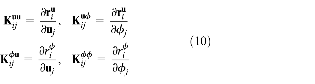
When the loading step size is small, a step-by-step solution strategy can be adopted, and the terms
Numerical simulation result
Standard example validation
The correctness of the program is verified by a classic example of a single-edge notched thin plate. As shown in Figure 1, a square sheet with a side length of 1 mm has a horizontal crack with a length of 0.5 mm on the edge of the sheet. Type I crack growth under uniaxial tension and type II crack growth under horizontal shear were calculated separately. The calculation parameters include the Lame constant, the crack regularization width parameter, and Griffith’s constant. For the convenience of comparison, the values are the same as in the literature. 27 The specific values of each parameter are shown in Table 1.

Geometry and boundary conditions of the models.
Parameters for phase-field model.

The boundary conditions of the uniaxial tensile model are: bidirectional constraints at the bottom, that is, ux = 0, uy = 0; left and right sides and top ux = 0. An upward displacement load is applied in the y-direction of the top, with a displacement of 1 × 10⁻⁵ mm per step for the first 500 steps, and a displacement of 1 × 10⁻⁶ mm for each step thereafter. Figure 2 shows the crack propagation path under uniaxial tension, and its morphology is completely consistent with the previous literature. 27

Type I crack propagation path: (a)
Figure 3 shows the load-displacement curve in the y direction at the top of the model. It can be seen from the figure that the cracks of the structure begin to expand when the vertical displacement reaches 5.6 × 10⁻³ mm, and the peak load reaches 710 N, which is basically consistent with the calculation results of Miehe et al. 27

Load-displacement curve of the model under uniaxial tension.
The boundary conditions of the horizontal shear model are: bottom bidirectional constraint, that is, ux = 0, uy = 0 left and right sides and top uy = 0. A horizontal displacement load to the right is applied in the top x direction, with a displacement of 2 × 10⁻⁵ mm per step for the first 400 steps, and a displacement of 5 × 10⁻⁶ mm for each step thereafter. Figure 4 shows the crack propagation path under horizontal shearing, and its morphology is completely consistent with the previous literature. 27

Type II crack propagation path: (a)
Figure 5 shows the x-direction load-displacement curve at the top of the model. It can be seen from the figure that the crack begins to expand when the horizontal displacement reaches 8.7 × 10⁻³ mm, and the peak load reaches 520 N, which is basically consistent with the calculation results of Miehe et al. 27

Load-displacement curve of the model under shear.
The calculation results of the classic examples of crack propagation through I and II are basically consistent with the previous ones, and the crack propagation path is the same, which verifies the correctness of the self-programmed program and can be used for crack propagation calculation.
Simulation of non-uniform rust expansion of a single steel bar
The corrosion of steel bars in reinforced concrete (RC) is not uniform, and the test shows that the corrosion area of steel bars in the natural state mostly presents an ellipse shape. Yuan and Ji
21
gave the distribution state of the steel corrosion layer before the RC swelled and cracked, as shown in Figure 6. In the polar coordinate system, the corrosion amount of each point on the surface of the steel bar is expressed by the radius loss, and the radius loss expression related to the polar angle is


Distribution of steel corrosion layer.
where R is the radius of the steel bar;
After the steel bar is corroded, the volume of the iron oxide generated expands, and the corroded volume is about three to four times the volume of the original steel bar. 3 When the rust fills the pores between the steel bar and the concrete, it will squeeze the surrounding concrete, resulting in a rust expansion force. The magnitude of the force is proportional to the corrosion volume, showing an ellipse shape, and the direction is opposite to the corrosion direction. The phase-field method is used to calculate the corrosion and expansion of RC. As shown in Figure 7, the RC specimen with a side length of 100 mm contains steel bars with a diameter of 16 mm inside, and the thickness of the protective layer is c. The rust expansion force distribution is shown in Figure 7, which is achieved by applying the corresponding nodal displacements on the reinforcement-concrete boundary. The displacements at different nodes are described by the same formula as equation (11):


Model of corrosion expansion of RC.
As shown in Figure 7, the bottom of the model is constrained by simply support, and displacement loads in the form of ellipses are applied to the nodes on the circular surface of the steel bar, where the maximum displacement of the nodes is
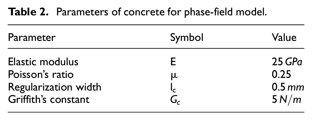
Parameters of concrete for phase-field model.
When the thickness of the protective layer is 15 mm, the calculation results are shown in Figure 8. When

Crack propagation with 15 mm concrete cover thickness: (a)
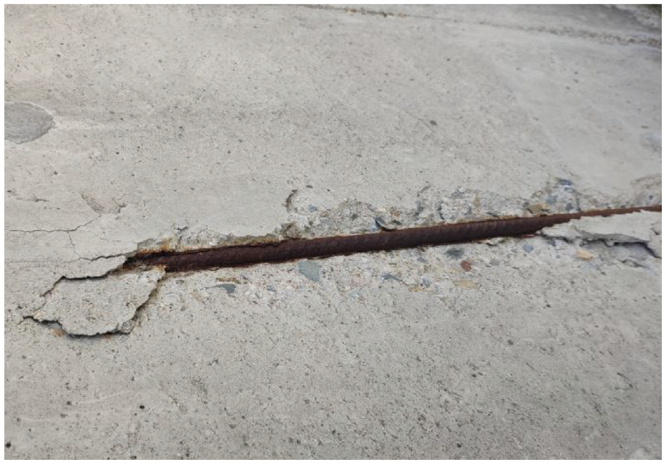
Wedge-shaped cracking of protective layer caused by corrosion of steel bar.
Adjust the thickness of the concrete cover to 20, 25, and 30 mm, respectively, and give a phase-field distribution diagram with a displacement of

Crack propagation with 20 mm concrete cover thickness: (a)

Crack propagation with 25 mm concrete cover thickness: (a)

Crack propagation with 30mm concrete cover thickness: (a)
Figure 13 shows the influence of the thickness of the concrete protective layer on the critical rust expansion force at the time of crack initiation. It can be seen from the figure that the critical rust expansion force is basically the same for the four calculation models, which is about 5.3 MPa. Therefore, the critical rust expansion force is not very sensitive to the thickness of the protective layer, and the thickness of the concrete protective layer has no obvious effect on limiting concrete cracks caused by corrosion of steel bars. This conclusion is consistent with the conclusion proposed by Xianli et al. 32 that the thickness of the protective layer has little effect on improving the corrosion damage durability life of concrete structures.
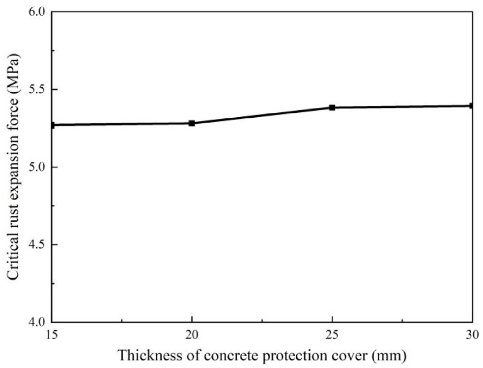
Critical rust expansion force for different concrete cover thickness.
However, a thicker protective layer actually has a significant effect on blocking the intrusion and carbonization of corrosive media, and can delay the corrosion time of steel bars. At the same time, the longer penetration path of corrosive medium can also reduce the corrosion rate of steel bars. In addition, comparing the crack propagation process of the protective layer thickness of 15, 20, 25, and 30 mm, it can be found that the thicker the protective layer, the slower the crack propagation, and the more difficult it is for the concrete protective layer to fall off.
It should be noted, however, that this section is still lacking in quantitative research. The main reason is that the calculation does not take into account the influence of factors such as the pores between the steel bar and the concrete, so the calculation ignores the process of the natural expansion of rust to fill the pores of the concrete. The calculation process only considers the tension stage and crack propagation stage of the protective layer, so the calculation results are conservative. However, in terms of qualitative research, the cracking law of steel bar rust expansion obtained by the phase-field simulation is in good agreement with the previous experiments and theoretical results, which preliminarily illustrates the feasibility of applying the phase-field fracture method to actual engineering simulation.
Simulation of non-uniform rust expansion of multiple steel bars
In actual engineering, the structure of a single steel bar is less, and the situation of multiple steel bars is more common, so this section calculates the corrosion and expansion of multiple steel bars. First calculate two steel bars, the thickness of the protective layer is 15 mm, the diameter of the steel bars is still 16 mm, and the distance between the two steel bars is 110 mm. The calculation parameters, constraints, load forms, and load steps are the same as for a single bar. The calculated crack propagation is shown in Figure 14. When the thickness of the protective layer is thin and the distance between the steel bars is large, the protective layer still cracks in a wedge shape, which is similar to that of a single steel bar. The difference is that when the crack propagates to the surface of the protective layer, there will be differences. Comparing Figure 8(c) with Figure 14(c), it can be found that the concrete protective layer will fall off when

Crack propagation with two steel bars rust:(a)
Adjust the concrete cover to 35 mm, and reduce the spacing between the steel bars to 70 mm. The calculation parameters, constraints, load forms and load steps are the same. The calculated crack growth is shown in Figure 15. At the initial crack propagation, the crack propagation morphology is similar to that of a single steel bar. However, when the crack further expands, the expansion path will be affected by adjacent cracks, and eventually the cracks are connected and penetrated to form layered spalling.

Crack propagation with four steel bars rust: (a)
Comparing the crack propagation of two steel bars and four steel bars, it can be found that when the concrete protective layer is thin or the spacing between the reinforcing bars is large, the wedge-shaped shedding of the protective layer may be caused by the rusting of the steel bars. However, when the concrete protective layer is thick and the spacing between the steel bars is small, the rusting of the steel bars will cause the protective layer to form layered spalling. This simulation result is in good agreement with the concrete rust crack morphology results observed by Cady and Weyers, 33 Bažant, 30 Zhou, 34 etc. This fully demonstrates the feasibility of the phase-field method to simulate the cracking and failure of concrete caused by steel bar expansion. The simulation results are close to the actual engineering, and complex crack propagation simulations such as corrosion damage of RC can be carried out.
Discussion
When the thickness of the concrete protective layer is 15 mm, once the steel bar is corroded, the concrete protective layer will easily fall off. The upper surface of the steel bar will be directly exposed to the air, jeopardizing the safety of the structure. The thickness of the concrete protective layer was adjusted during the simulation. It was found that the thickness of protective layer had no obvious effect on limiting concrete cracks caused by corrosion of steel bars. However, increasing the thickness of the protective layer could delay the speed of crack propagation and prevent the protective layer from falling off easily. However, increasing the thickness of the protective layer will undoubtedly increase the penetration path of the corrosive medium, thus delaying the time of corrosion damage of the reinforced concrete (RC) structure. In addition, there are the following advantages when the protective layer is not peeled off. On the one hand, this does not lead to direct exposure of the steel bar to the air, avoiding the risk of accelerated corrosion. On the other hand, for buildings such as traffic, the risk caused by the sudden falling off of the protective layer is avoided, and the integrity of the structure is maintained. 8
The brittle fracture phase field used in this paper simulates the corrosion failure of RC, and the crack propagation path is consistent with the observed actual crack propagation path. However, it should be pointed out that concrete belongs to quasi-brittle failure, and there is obvious strain softening phenomenon in the failure stage.35,36 In subsequent studies, the strain softening properties of concrete materials need to be considered. It is necessary to improve the phase-field method so that it can simulate quasi-brittle failure and make the simulation results more refined. In addition, the material properties of concrete used in this paper are single, while concrete is a composite material, in which the material properties of coarse aggregate, mortar and its joint surface are different. Therefore, for a small calculation model, the distribution of different aggregates can be considered, so that the simulated crack propagation is closer to the real situation.
At the same time, according to the actual situation, the cracking of the concrete protective layer caused by the corrosion of multiple steel bars is simulated. The simulation results show that when the concrete protective layer is thin and the spacing between the steel bars is large, the concrete protective layer will produce wedge-shaped cracking, which is the same as the corrosion failure of a single RC. When the concrete protective layer is thick and the spacing between the steel bars is large, the cracks will fuse and connect with each other as they expand. Penetrating cracks will be formed, resulting in the layered spalling of the protective layer. The simulation results are in good agreement with the experimental and engineering observations. Since only two kinds of reinforcement distributions in the concrete are simulated in the paper, no simulations are made for other situations. In future studies, different cover thicknesses and different rebar spacings can be simulated. When the simulation situation is increased, a quantitative relationship can be proposed according to the thickness of the protective layer and the spacing of different reinforcement bars. In this way, the damage form of the protective layer after the corrosion of the steel bar can be predicted.
Based on the traditional finite element framework, there are two main ways to describe crack propagation. One is the geometric description method based on grid expansion, including: element deletion method, 37 interface element method. 38 However, in such methods, cracks can only propagate on the grid or on the grid boundary, so the crack propagation has grid dependence and numerical instability. The other category is non-geometric description methods, including extended finite element, 39 and phase-field methods. In this kind of method, the crack propagation can be separated from the grid and propagate inside the grid. However, the former has a weak ability to deal with complex cracks, and is not suitable for simulating the propagation of concrete cracks caused by corrosion of steel bars. The phase-field method has the ability to deal with complex crack propagation, which is more suitable for dealing with the propagation of concrete cracks, and is easily applicable to three-dimensional calculations.
Of course, the calculation accuracy of the phase-field method is closely related to the mesh density. 40 Therefore, fine meshing is required, which often requires a long calculation time. In order to improve the computational efficiency, dynamic adaptive mesh technology can be used to refine the mesh only on the crack propagation path. In subsequent research, dynamic adaptive grid technology can be used, combined with efficient numerical solution methods, to improve the simulation efficiency of RC corrosion damage.
Conclusion
This paper attempted to introduce the phase-field method into the calculation of concrete structure damage caused by steel corrosion, and simulates the crack propagation process of the concrete protective layer. The correctness of the program adopted in this paper is verified by the basic example of uniaxial tension and shear. Then, the calculation model of reinforced concrete (RC) is established. According to the basic shape of the corrosion layer when the steel is corroded, the distribution of the rust expansion force on the concrete is given, and the displacement load is applied to the calculation model.
The crack propagation path obtained by the simulation is consistent with the observed concrete cover shedding morphology. When the thickness of the concrete protective layer is thin and the spacing between the rebars is large, the rust expansion of the rebar will easily lead to the wedge-shaped shedding of the protective layer. This will accelerate the corrosion of steel bars and endanger the safety of the structure. When the thickness of the concrete protective layer increases and the spacing between the reinforcing bars decreases, the cracks will fuse and connect with each other when they expand. Penetrating cracks will be formed, and the protective layer will fall off in layers. However, at this time, the steel bar will not be directly exposed to the air before the protective layer falls off in layers, and the corrosion rate will not be accelerated.
Through simple and complex steel bar corrosion leading to cracking of concrete protective layer, the feasibility of phase-field method for RC corrosion damage simulation is illustrated. It can provide reference for engineering design and durability research of complex RC structures.
Footnotes
Handling Editor: Chenhui Liang
Author contribution
Caihong Zhang: Conceptualization, Methodology, Programming, Writing-original draft, Writing – review and editing. Wenqiang Xu: Conceptualization, Methodology, Programming. Jialing Yang: Conceptualization, Methodology, Programming, Writing – review and editing. Kaizhong Cao: Methodology, Investigation, Writing – review and editing. Debing Wen: Programming, Investigation. Xusheng Wang: Programming, Investigation.
Declaration of conflicting interests
The author(s) declared no potential conflicts of interest with respect to the research, authorship, and/or publication of this article.
Funding
The author(s) disclosed receipt of the following financial support for the research, authorship, and/or publication of this article: This research was funded by Postgraduate Research & Practice Innovation Program of Jiangsu Province, grant number KYCX22_0641 and the Henan Province Science and Technology R&D Project, grant numbers cscec7b-2020-Z-21, cscec7b-2020-Z-25.