
Abstract
The principle of connecting rod (con-rod) fracture splitting was analyzed, and the microscopic morphology of fracture surface was observed using scanning electron microscope. Crack initiation and propagation during the fracture splitting of con-rod process was numerically simulated. The effects of the bolt hole on the fracture splitting force and distribution of stress and strain were investigated. Typical location of fracture splitting defects and why they were generated were analyzed, and methods were proposed to avoid them. The results show that the nature of con-rod fracture splitting is a mode I quasi-brittle fracture, and the position of crack initiation can be found during the analysis process. Existence of the bolt hole is helpful to optimize fracture splitting technology and improve product quality, and the optimized range of bolt hole position was achieved based on simulation result. Moreover, defects such as steps, break-outs, usually occur between the bolt hole wall and outer edge of the con-rod big end in that two cracks converged and propagation velocity was slow in this region. The fracture splitting defects can be reduced or avoided when the outer shape of the fracture surface is a circular arc.
Keywords
Introduction
A connecting rod (con-rod), whose big end is connected to the crankshaft and small end is connected to the piston, is one of the key parts of an automobile engine. Transmitting and transforming energy are the important functions of con-rod. The work environment of con-rod is extremely harsh in the automobile engine.1,2 According to the crankshaft structure, the big end of a con-rod is divided into two parts, including a cap and a rod. In traditional method, the big end of a con-rod is cut off by a milling cutter. There are two major requirements: (1) the cap and rod should have high precision rejoining surfaces, which is required by later machining procedures, such as rough grinding and finish grinding and (2) the structures of bolts are used to position. Therefore bolt holes need to be perpendicular to rejoining surfaces. All these requirements greatly increase the difficulty of processing, procedures and cost. However, the fracture splitting (FS) technique of con-rod, which is a high-precision manufacturing technology based on the crack technology and stress concentration principle of fracture mechanics has solved the above questions perfectly. The big end of a con-rod is divided into a cap and a rod using FS technology, which can improve the production efficiency and reduce cost. 3 At the same time, the jagged fracture surface is obtained, which provides the precise three-dimensional position between the cap and rod, and significantly improves assembly quality and load bearing capacity.
FS technology has become the development situation of future for con-rod processing because of its significant economic benefits and quality advantages, and has been increasingly applied to production. FS material, FS force, notch processing methods and parameter optimization 4 were extensively researched to optimize FS technology and reduce the defect rate of products. For example, the FS force can be determined according to the relationship between the J-integral value and the stress intensity factor, which can help to select the optimal notch parameters, and so on. 5 Research on con-rod FS in the past usually focused on crack initiation near the notch. However, FS of the con-rod is different from the fracture of general notch specimens, because of the intricate structure of the big end. The machining position of the bolt hole and the shape design of theoretical fracture surface affect the FS process and product quality. Additionally, it has been found in production that FS defects generate easily at the outer edge of the big end of the con-rod, 6 rather than the region where the crack initiates. Consequently, investigation into three-dimensional crack propagation is necessary.
In this article, according to the fracture mechanics theory of a notch specimen, the process of the FS of a C70S6 con-rod was simulated by “element death” technique of the finite element method. 7 Three-dimensional crack initiation and propagation were analyzed, and the distribution of stress and strain at notch tip was investigated. The path and the velocity of crack propagation were determined. The effects of both bolt hole and shape of fracture surface on the process of FS were studied, and the reasons for FS defects were analyzed. This study provides a reference for the design of the position of the bolt hole and the shape of the fracture surface, which help to improve the FS quality and efficiently reduce defect rates. The validity of the analysis results has been proved by experiment.
Principle of con-rod FS
The stress state of the local region of specimen is changed because of a notch, which causes a triaxial stress state and stress concentration at the notch tip. 8 The load applied on notch specimen and the stress field near notch tip are shown in Figure 1(a) and (b). There is high longitudinal stress (σy) at the notch tip, leading to transverse shrinkage because of the Poisson effect. Conversely, the adjacent area tends to retain its original size, leading to the generation of the transverse stresses σx and σz and the formation of a triaxial stress state, which leads to occurrence of brittle fracture instead of plastic deformation.
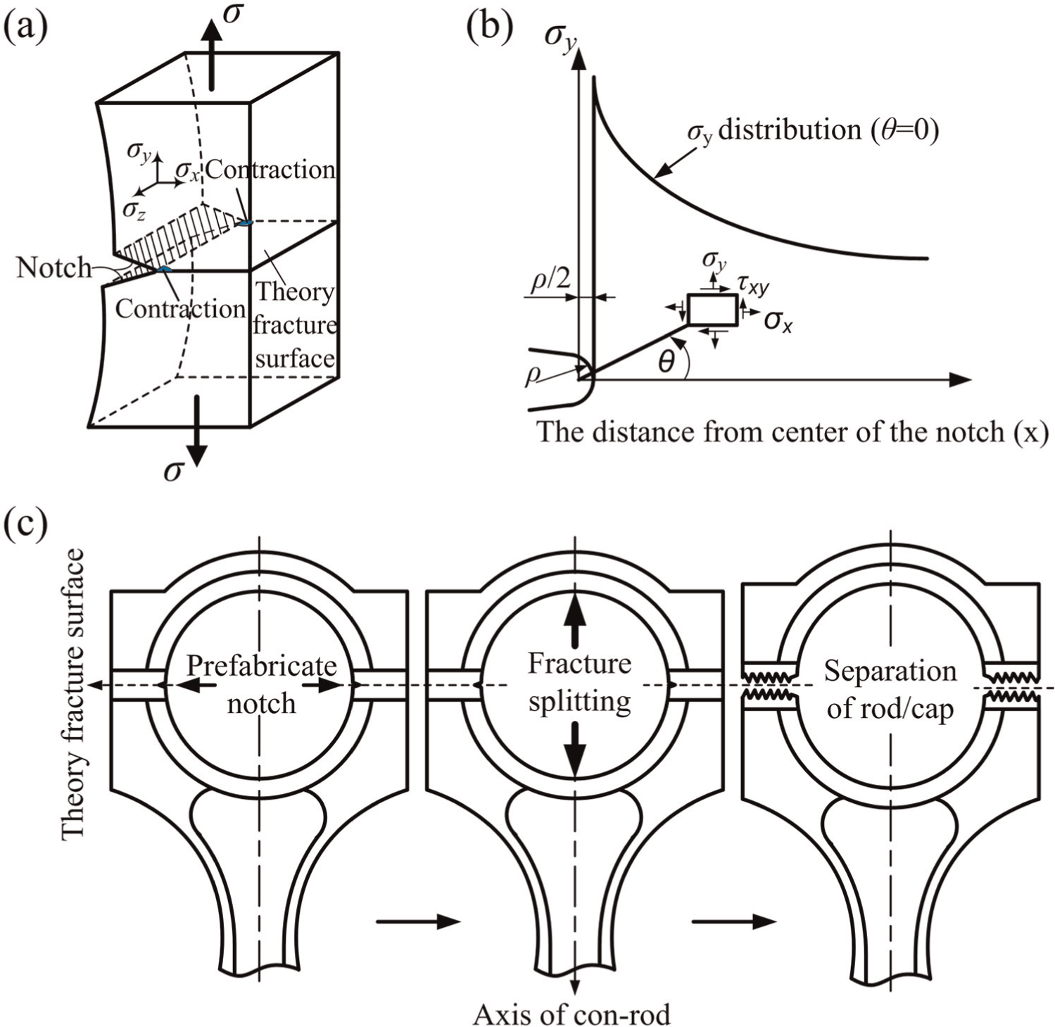
(a) The notch specimen subjected to load and Poisson effect diagram, (b) stress field near notch tip and (c) process of the con-rod FS.
The FS technology of a con-rod uses stress concentration effect of notch and the notch sensitivity of material to change the stress state of the designated region, which makes the material yield strength in this region higher than the brittle fracture strength that is required to achieve a brittle fracture. 9 The process of FS is shown in Figure 1(c).10,11 On the inner side of the big end hole of the con-rod, two symmetrical notches with the same shape and size are first cut as grooves by a neodymium-doped yttrium aluminum garnet (Nd:YAG) laser. 12 Then, a load is applied perpendicular to the theoretical fracture surface. With the increase of load, higher stress will be induced near the tip of the notch. Cracks will initiate at this tip and propagate rapidly until the con-rod is divided into two parts, that is, a cap and a rod.
Fracture criterion of con-rod FS
Stress components at the notch tip can be formulated as follows, and its coordinate system is shown in Figure 1(b) 13
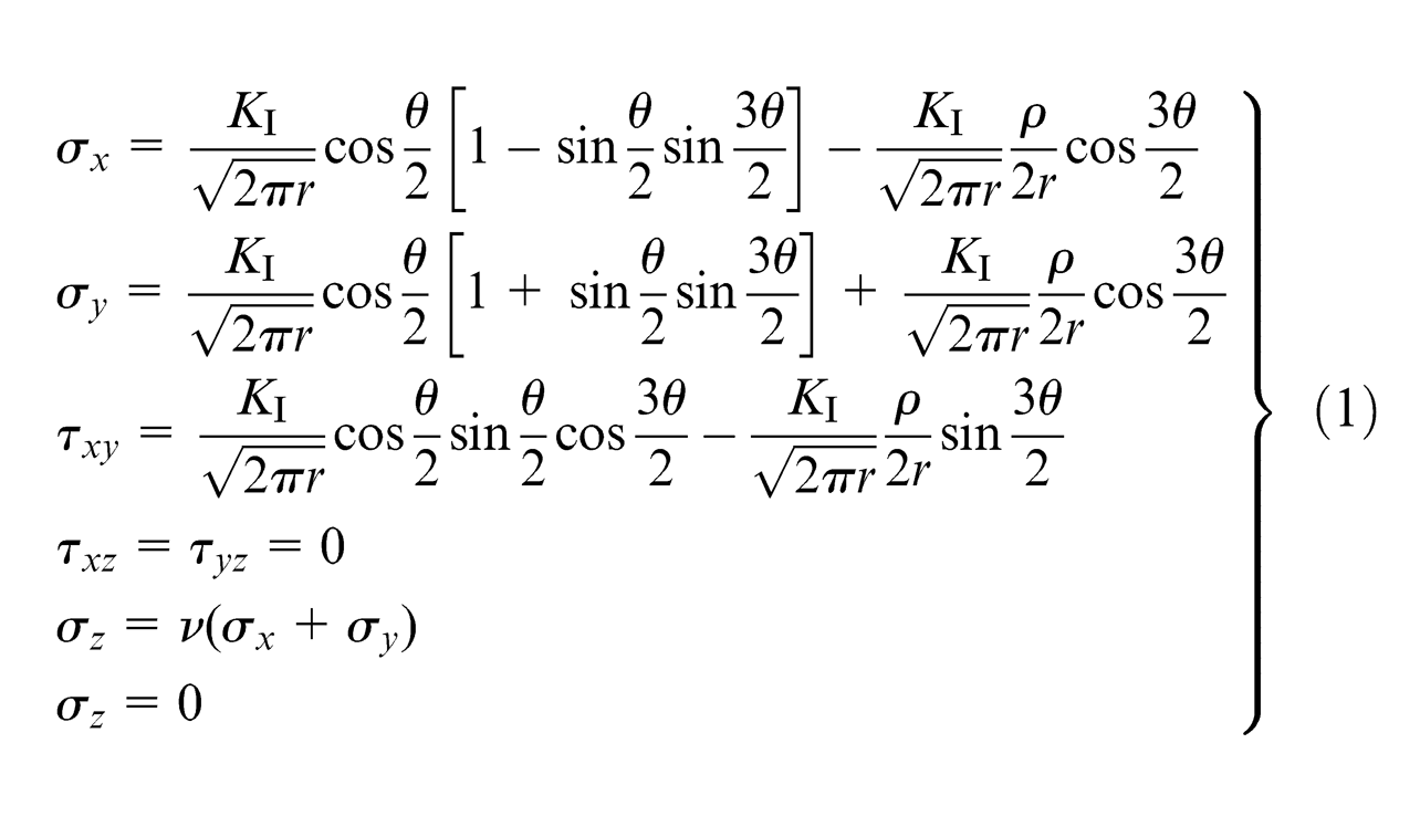
where ρ is the curvature radius at the notch tip, r and θ are the polar coordinates of a point near the tip, σx, σy, σz, τxy, τxz and τyz are the stress components, ν is the Poisson’s ratio and KI is the apparent stress intensity factor. KI represents the strength of stress field at notch tip, which was affected by load and notch. Under the constant value of ρ, there is a critical value of KI, which is considered as the apparent fracture toughness (KIA) of material. KIA can be obtained by Charpy experiment using V-notch specimen. With the increase in load, KI reaches to KIA. At that moment, the material is damaged and micro-cracks arise. So the fracture of con-rod depends on whether the stress at notch tip reaches the fracture standard of the material. To select the right criterion of fracture, the investigation on the nature of fracture of con-rod FS is essential.
To determine the nature of the fracture, microscopic morphology of the fracture surface was observed using a scanning electron microscope (SEM) after the FS of the C70S6 con-rod, as shown in Figure 2. The quasi-brittle fracture surface was observed. The river pattern can be seen from the microscopic morphology, which is a characteristic of cleavage fracture. According to the way the external load is applied, FS of the con-rod belongs to the mode I fracture category. The nature of FS is quasi-brittle fracture after yielding in a small region of the elastic–plastic material, and analysis by linear elastic fracture mechanics could be used. Fracture will generate when the maximum principal stress reaches the limit of the fracture stress of the con-rod. The maximum principal stress criterion can be used in quasi-brittle fracture, which is regarded as unifying the crack propagation fracture and regular strength criteria. Its accuracy has been proved by experiment and practice. 14
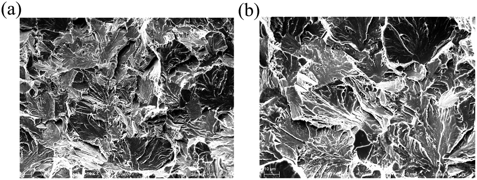
Microscopic morphology of the fracture surfaces: (a) under 1000 times and (b) under 2000 times.
Finite element modeling of con-rod FS
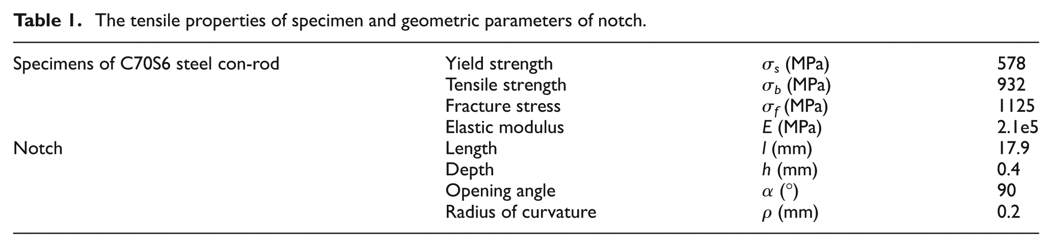
Before FS, the diameter of the big end hole of the con-rod is 41.8 mm and the diameter of bolt hole is 6.5 mm. The center distance between the big end and small end holes is 147.5 mm, and the thickness of the con-rod specimen is 17.9 mm. The material used for the con-rod specimen is C70S6 steel. Tensile test was executed to obtain the tensile properties of the specimen. The tensile properties and geometric parameters of the notch are shown in Table 1.
The tensile properties of specimen and geometric parameters of notch.
Because of the symmetry of the con-rod and the minimal effect of the small end, only a quarter of the big end was modeled in this study, as shown in Figure 3(a).
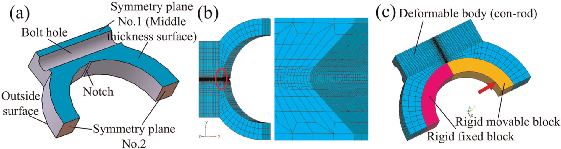
Finite element model: (a) geometry model of big end, (b) mesh and (c) contact and load.
The result of meshing is shown in Figure 3(b). The mesh refinement is taken into particular consideration in the specific area where the crack propagates. 15 In order to conserve computer resource and improve computational speed, the model was meshed into a hexahedral meshwork using the transition sub-network method. Literature showed that an element size equal to 0.05 mm yields optimum results. 16 The conclusion was in agreement with the tests using numerical analyses, so the side lengths of hexahedral element were set to 0.05 mm at crack propagation region. The maximum value of the element aspect ratio was 1:2, and the minimum value of the Jacobian was 0.92 beyond crack propagation region.
The boundary conditions were defined in accordance with the actual working conditions, as shown in Figure 3(c). There were two contact pairs. One was between the deformation body and rigid fixed block, and the other was between the deformation body and rigid movable block. The rotation and displacement in all directions of the fixed block were fixed. For the movable block, the rotation and the displacement in x-axis and z-axis were fixed, and displacement in y-axis was applied. The movement velocity of movable block along y-axis was about 14 mm/s in accordance with actual conditions. Moreover, uz = 0 on nodes in plane 1 and ux = 0 on nodes in plane 2. Due to mode I loading, the friction between the crack surfaces is not considered in the modeling.
After building the finite element modeling, a mesh element was hypothesized to die when its maximum principal stress reached to the presetting fracture stress (σf) in the process of calculation. The dead element would not to be displayed anymore in the modeling, so crack propagation process was numerically simulated. Then, the path of crack propagation can be clearly observed.
Results and discussion
Crack growth and stress distribution
Figure 4 shows the first principal stress distribution during the process of crack initiation and propagation. It can be seen that the stress distribution is symmetrical on both sides of the theoretical fracture surface, namely, on the direction of θ = 0 (as indicated in Figure 1(b)). High stress distribution is in the shape of a butterfly at the notch tip and crack tip, and it exhibits the most significant effect of stress concentration. The initiation point was measured to be about 0.05 mm away from the notch tip of the middle thickness surface. Under the loading velocity in accordance with actual conditions, the propagation distance of the crack was about 11.75 mm and took about 0.0006 s to propagate to the end after initiation. Thus, the average calculated velocity of propagation was about 19.6 m/s. During the propagation process, compressive stress existed outside of con-rod.
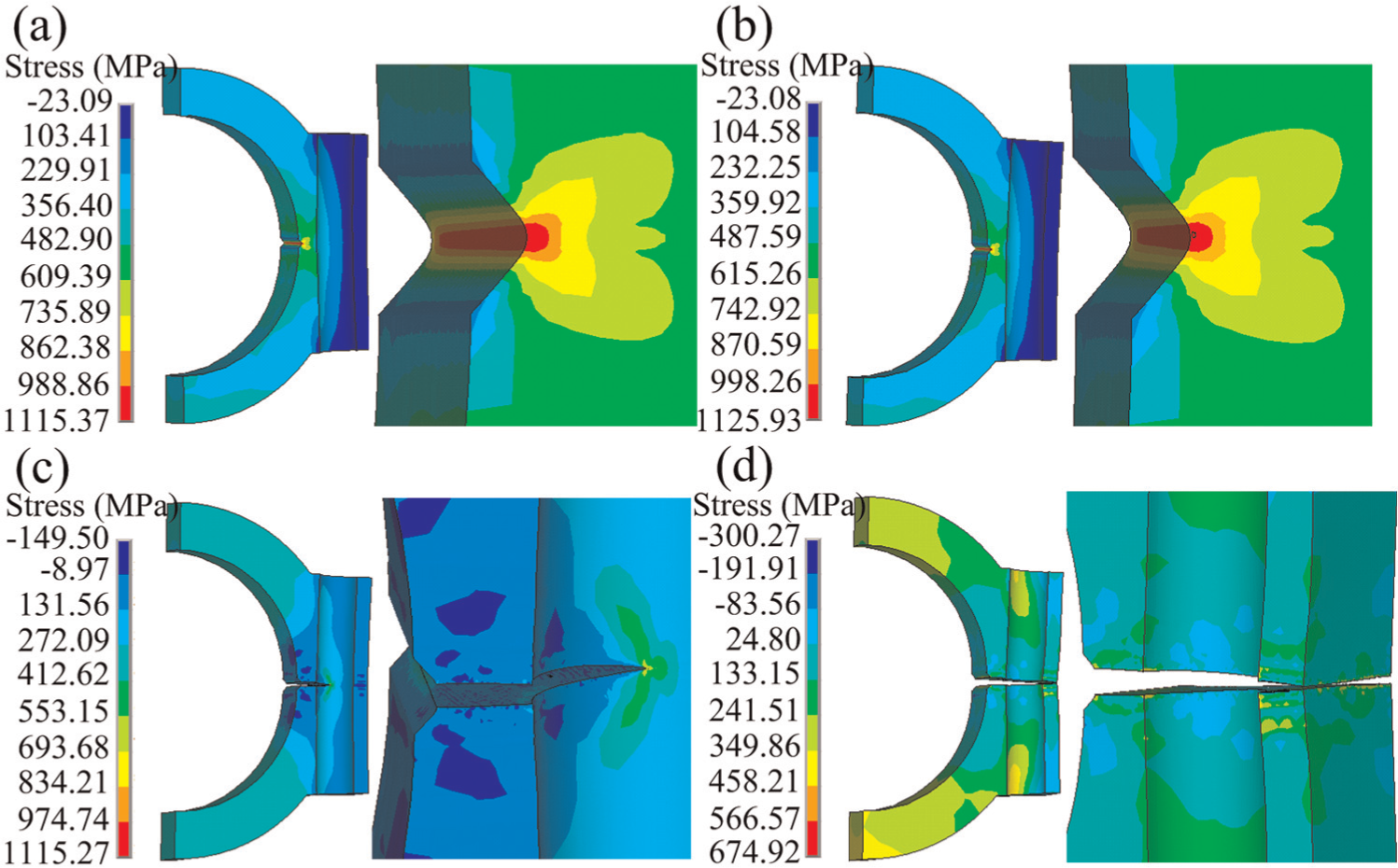
The distribution of first principal stress during crack growth process: (a) before crack initiation, (b) crack initiation, (c) propagation and (d) propagation end.
The law of stress distribution in special locations (lines 1–3) has been analyzed, and special locations are shown in Figure 5(a). Figure 5(b)–(d) shows the distribution curve of principal stress and equivalent stress at the notch tip (line 1) and notch bisector (lines 2 and 3) at the crack initiation. It can be seen from Figure 5(b) that the principal stress and equivalent stress increase rapidly in the range of distance 0.7 mm from the outside surface and increase slowly outside the range. As shown in Figure 5(c) and (d), the three-dimensional high stress region at the notch bisector concentrates in the range of 0.5 mm from the notch tip. The point with the highest first principal stress is located at about 0.05 mm from the notch tip on the middle thickness surface. The second principal stress and third principal stress are relatively high in this peak point, where the crack initiates.
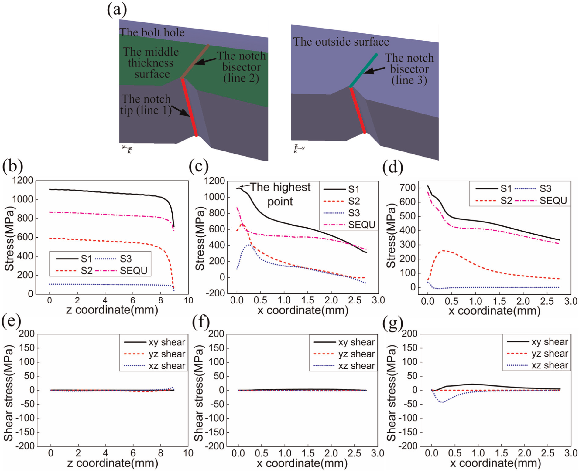
(a) The special locations near notch (lines 1–3), (b) the distribution curves of principal stress and equivalent stress at the line 1, (c) the distribution curves of principal stress and equivalent stress at the line 2, (d) the distribution curves of principal stress and equivalent stress at the line 3, (e) the distribution curves of shear stress at the line 1, (f) the distribution curves of shear stress at the line 2 and (g) the distribution curves of shear stress at the line 3.
Figure 5(e)–(g) shows the distribution curve of shear stress at the notch tip and notch bisector at the crack initiation. It can be seen that the shear stress is approximately equal to 0 at notch tip and notch bisector, meaning that the shear stress does not exist on the theoretical fracture surface.
Influence of the bolt hole on the FS of the con-rod
Figure 6 shows the FS force, plastic deformation and stress distribution in the simulations using con-rod specimens with and without a bolt hole. As shown in Figure 6(a) and (b), the FS force is reduced by 40% and the plastic deformation of the con-rod big end is reduced by tenfold with the existence of the bolt hole. The decrease in the FS force can decrease the requirements on the FS equipment. The decrease in the plastic deformation of the big end hole can reduce its ovality defect. As shown in Figure 6(c), the point with maximum value of the first principal stress at the notch tip is found on the middle thickness surface using con-rod specimens with a bolt hole. The stress value is basically the same as that of the con-rod specimens without a bolt hole except the value near the outside surface, which leads to the non-uniqueness of the crack initiation point. This will reduce the quality of FS con-rod.
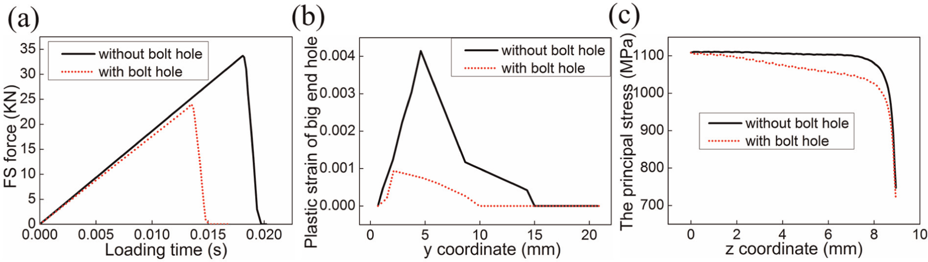
The effects of bolt hole on FS force, plastic deformation and stress distribution: (a) the effect of bolt hole on FS force, (b) the effect of bolt hole on plastic deformation of big end hole and (c) the effect of bolt hole on the first principal stress at notch tip.
Besides, if the bolt hole is machined on the cap and rod separately after FS, both the positioning of bolt hole and chucking of a cap and rod will be very hard. Accordingly, the existence of the bolt hole is beneficial to optimize the FS process.
Toughness of materials is a measure of a material’s resistance to fracture or crack propagation. 17 It is often expressed in terms of the energy requirements to produce new fracture surface, as the crack grows towards the critical condition for fracture. 18 The position of the bolt hole has an effect on FS process, because the thickness of the specimen affects its fracture toughness. 19 To analyze this law, the values of B′ and B″ were set in Figure 7(a).
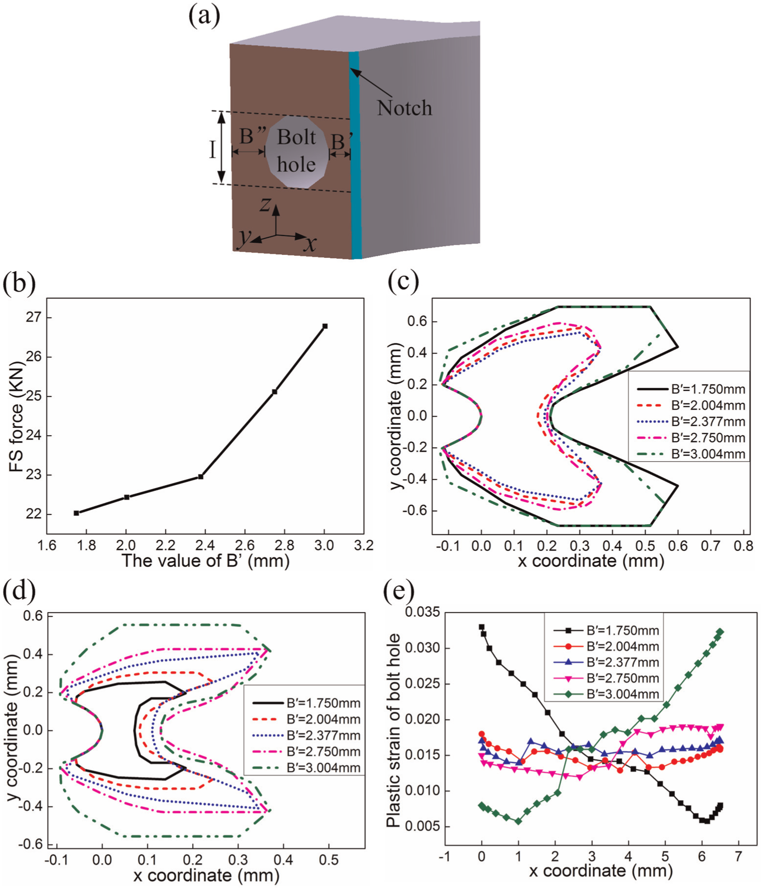
(a) Cross-sectional view of the big end along the direction of theoretical fracture surface, (b) the effect of bolt hole location on the FS force, (c) the effect on the plastic deformation near notch tip on the middle thickness surface, (d) the effect on the plastic deformation near notch tip on the outside surface and (e) the effect on the plastic deformation of bolt hole on fracture surface edge.
Five series of B′ and B″ are shown in Table 2. The results of comparing the effects of different bolt hole positions on the FS force and the plastic deformation are shown in Figure 7(b)–(e).
B′ and B″ for different locations of bolt hole.
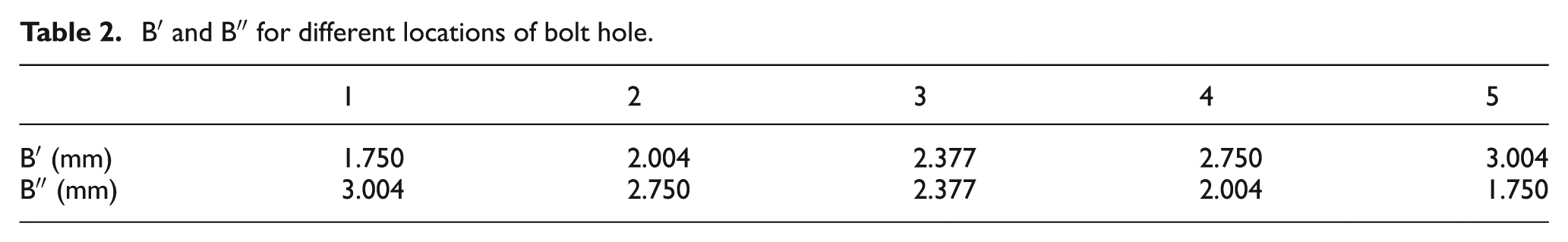
Figure 7(b) shows that the effect of different bolt hole location on the FS force. It can be seen that the FS force rise along with the increase in the value of B′. When B′ is less than 2.377 mm, the FS force increases more slowly. As shown in Figure 7(c), when the B′ is equal to 1.750 or 3.004 mm, the range of plastic deformation near notch tip on the middle thickness surface is lager. As shown in Figure 7(d), the range of plastic deformation near notch tip on the outside surface increases with increase in the value of B′.
With the variation of value B′, rules on the plastic deformation zones of the middle surface and the outside surface are different. The reason is that the bolt hole is located inside the fracture surface and far from the outside surface. So its location only affects the size of non cracking strip along the x-axis in region I near notch, but does not affect the size of non cracking strip along the x-axis on outside surface near notch, as shown in Figure 7(a). For the middle surface, when the B′ is equal to 1.750 mm, the thickness between the notch tip and the bolt hole wall is thin, plastic deformation occurs easily. When B′ is equal to 3.004 mm, crack initiation needs larger FS force. The larger FS force also leads to the increase of plastic deformation. For the outside surface, the plastic deformation range is only controlled by the change of FS force. As shown in Figure 7(b), the FS force rises with the increase in the value of B′. So the plastic deformation on the outside surface increases with the increase in the value of B′.
The position of the bolt hole has affected the deformation of the bolt hole as shown in Figure 7(e). With the increase in the B′ value and the decrease in the B″ value, the bolt hole deformation near the notch is decreased. In contrast, the bolt hole deformation far from the notch is increased. When the value of either B′ or B″ was lower than 2 mm, the bolt hole deformation on the corresponding side increased noticeably. But when the values of B′ and B″ were both greater than 2 mm, the variation in the plastic deformation was not obvious.
To sum up, the FS force is relatively low and the plastic deformation range is relatively small when the value of B′ is between 2.0 and 2.75 mm. The plastic deformation of the bolt hole is small when the value of B′ and B″ is greater than 2 mm. Therefore, the B′ should be controlled between 2.0 and 2.75 mm and the B″ should be greater than 2 mm in processing of con-rod FS.
Cause and preventive measures for FS defects
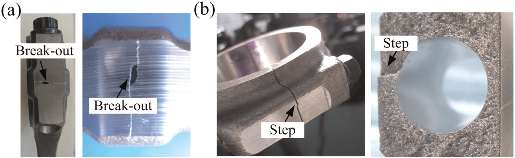
FS defects have been usually found in production, such as break-outs, steps, and so on. As shown in Figure 8, several defects are usually located on the outer edge of the con-rod big end. This article analyzed the cause of defects occurrence from crack propagation view. Path and velocity of crack propagation was achieved by numerical simulation. The left side of Figure 9 shows the path of crack propagation. The color stands for time changing, and the black curve stands for crack front line at this moment, so the color stripe between the two black curves is one time step. The right side of Figure 9 shows the velocity of crack propagation. Based on the different propagation velocities, the fracture surface is divided into several regions.
FS defects found in experiments: (a) break-outs and (b) steps.
(a) Crack propagation path and velocity of actual fracture surface, (b) changing the design of outer shape of the fracture surface, (c) crack propagation path and velocity of trapezoid fracture surface and (d) crack propagation path and velocity of arc shape fracture surface.
It can be seen from Figure 9(a), the crack initiates at the notch tip and propagates to the front and to the outside surface at the same time. The main crack divides into two parts when it reaches the bolt hole and then converges after passing by the bolt hole. The steps easily occurred in region IV where the two cracks converge. When the cracks propagate to region V, the propagation velocity is lower because of the extrusion pressure in this region, leading to break-outs.
Therefore, the reduction in the ranges of the regions IV and V and the increase in the propagation velocity can reduce the incidence of defects. In this article, changing the design of outer shape of the fracture surface was taken into account. As shown in Figure 9(b), basic dimensions of the con-rod remains the same, and trapezoid fracture surface could be attained by tilting two end lines 30° inward. Another shape of fracture surface outer edge was designed for circular arc, which was required to be concentric with bolt hole and tangent to the two tilted end lines. Figure 9(c) and (d) shows the crack propagation simulation results.
According to Figure 9(c) and (d), it can be seen that when the outer shape of the fracture surface is a circular arc, there is no obvious boundary between regions IV and V. The ranges of these two regions are small, and the crack propagates rapidly. Therefore, the arc shape fracture surface is the most suitable within the acceptable range for practical application.
To validate the simulation results and facilitate practical production, C70S6 con-rods were fracture split in the FS facility with a drop-off wedge invented independently by Jilin University (as shown in Figure 10(a)). The results show that the quality of FS con-rod with arc shape fracture surface is good, and the defect rate is almost null. Figure 10(b) shows the FS con-rods without the break-out and the step defects.
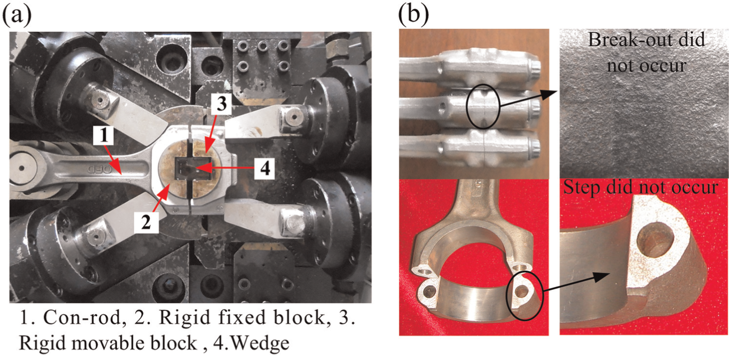
Experimental setup of con-rod FS: (a) experimental facility and (b) experimental results.
Conclusion
According to how the external load applied and micro morphology of the fracture surface, the nature of FS is a mode I quasi-brittle fracture after yielding in a small region of the elastic–plastic material. The results of numerical simulation show that the point of crack initiation is located at about 0.05 mm from notch tip on the middle thickness surface. The stress distribution is symmetrical on both sides of the theoretical fracture surface and shear stress is equal to 0 on the theoretical fracture surface.
The FS force can be reduced by 40% and the plastic deformation of the big end of the con-rod can be reduced by tenfold under the existence of the bolt hole. Besides, the existence of the bolt hole changes stress distribution at notch tip, which leads the point of crack initiation to be unique. Analysis of the effect of different bolt hole location on FS shows that the distance between the notch tip on the middle thickness surface and the bolt hole wall should be controlled between 2.0 and 2.75 mm. The distance between the bolt hole wall and outer edge of the fracture surface should be larger than 2 mm. Under this condition, the quality of the FS is the best.
The main crack will divide into two parts when it reaches the bolt hole, and these cracks then converge after passing the bolt hole. When the two cracks converge, some defects might occur, such as steps. During the propagation process, compressive stress exists outside the con-rod, causing low velocity of crack propagation, which finally leads to FS defects, such as break-outs. When the outer shape of the fracture surface is a circular arc, the range where defects are prone to occur is decreased. Moreover, the crack propagation velocity in this range is increased, which can help to reduce the FS defects rate.
Footnotes
Appendix 1
Declaration of conflicting interests
The authors declare that there is no conflict of interest.
Funding
This work was supported by the National Science and Technology Major Project (2013ZX04002021) and International Science and Technology Cooptation Project (2011DFR 70350).