
Abstract
Aiming to more accurately control the wheel speed of an electric vehicle (EV) driven by four in-wheel motors, a developed whale optimization algorithm-proportional–integral–derivative (KW-WOA-PID) control algorithm is proposed herein. In this study, mathematical and simulation models are built for EVs by analyzing the mechanical structures of EVs driven by four in-wheel motors. Simulations are conducted, and the driving and control requirements for the in-wheel motors are obtained. Then, mathematical and simulation models are built for a specific in-wheel motor. The whale optimization algorithm (WOA) is optimized by kent mapping and the adaptive weight coefficient to improve the ability of the algorithm to jump out of the local optimum and the convergence speed and convergence accuracy of WOA. Then the further simulations are conducted. The simulation results display that the maximum overshoot and adjustment time of the motor under KW-WOA-PID control are significantly optimized. Then, a speed-control bench test system is built for the in-wheel motor, and real-life experiments were conducted. The experimental results verify that KW-WOA-PID has higher control accuracy and a better response performance; accordingly, the developed control algorithm can meet driving requirements. The handling stability of EVs is effectively improved by controlling the motor speed.
Introduction
In view of the increasing global energy and environmental crises, people worldwide attach increasing importance to electric vehicles (EVs), which have these advantages, such as high efficiency, energy saving, and zero emissions. The technologies for EVs driven by four in-wheel motors, with higher transmission rate and lighter chassis, become an important field of study.
At present, scholars worldwide have focused their studies on the driving systems of EVs. Some control strategies were proposed to improve the handling stability of electric vehicles.
Joa et al. 1 proposed a control algorithm for four-wheel independent braking by analyzing automotive dynamics, so that automotive stability could be enhanced on different road surfaces. It provides a reference for the dynamic analysis of electric vehicles in this study. A stability controller was developed and used in a vehicle with four-wheel independent braking, driving, and steering. A direct torque control strategy was employed to improve the handling stability and maneuverability of the body. 2
A design method for integrated chassis controllers for four-wheel independent steering was proposed by Yim 3 based on a front slip angle constraint, and the automotive transverse stability and mobility were enhanced. Nonlinear model predictive control was applied in the motor torque-vectoring and the control of front-to-total anti-roll moment distribution of four-wheel-drive EVs so that power loss was reduced and automotive steering response under stable and transient state were enhanced. 4
As the drive-wheel torque of the EV could be controlled, the four-wheel driving and braking torque were controlled through adjusting the output torque of the in-wheel motors. The pseudo inverse optimization algorithm was employed to optimize and distribute the driving torque of each wheel, so that transversal stability control of the EV could be realized. 5 Chhlonh et al. 6 improved the handling stability of electric vehicles by proposing a hybrid Fuzzy-PI speed controller to control brushless DC motors. Pang et al. 7 proposed a composite adaptive backstepping robust tracking controller to improve handling stability of EVs. Although the actual application is not yet mature. The simulation results were very good, mathematical modeling of the literature provides great reference for this study.
It can be discovered from the above literature that some scholars have studied the handling stability of electric vehicles from different perspectives. It is a very effective solution to control the handling stability of electric vehicles by controlling the motor. The research on the control of the motor torque of electric vehicles is relatively rich and adequate, but the research on the control of the motor speed is almost a blank up to now.
Dogan et al. 8 proposed a robust adaptive electric vehicle control model and position control method based on vehicle dynamics, which provided a reference for the mathematical modeling of this study. The bicycle model (also known as the monorail model) used by Park et al. 9 in his thesis helped to model the entire 4WD electric vehicle for this study. Another study applied different metaheuristic technologies in DC motor speed adaptive control with uncertain parameters. The simulation results indicated that the proposed adaptive control strategy could help EVs adapt to different working condition by adjusting the motor speed, and demonstrated that an adaptive control strategy based on a metaheuristic algorithm had many advantages. 10
Masoudi et al. 11 employed fuzzy logic system to realize the adaptive control of linear motors and the proposed control strategy had good adaptability without being influenced by motor dynamic uncertainty. Rohan et al. 12 proposed a fuzzy logic-based PID controller gain tuning method to improve the response performance of the controller. The motor was controlled by the optimized PID controller, so that the acceleration and speed of electric vehicle could achieve best balance. Feng and Zheng 13 used the fuzzy self-tuning PID control method to simulate the operating conditions of the vehicle, and conducted a joint simulation analysis to contribute to the realization of the vehicle anti-lock braking. The fuzzy self-tuning PID control method of the combined brake of the in-wheel motor-driven electric vehicle was studied. George et al. 14 used the ant colony optimization (ACO) algorithm to tune the parameters of the PID controller to effectively control the speed of electric vehicles. Dutta and Nayak 15 reported that brushless DC motors were superior to brushed DC motors. A proportional–integral–derivative (PID) controller, as optimized by the grey wolf algorithm for finding the PID parameters, was used to control the brushless DC motors. This paper expounds the method of optimizing PID controller through optimization algorithm, and provides a basis for the selection of the type of motor used in this study. Some scholars also applied HHO and PSO algorithms to optimize PID controller parameters to achieve better controller effects.16,17
Based on above research, the PID controller is finally selected as the controller of this study, given its maturity, easy usage and strong applicability.
Yin et al. 18 analyzed the mathematical model, operated characteristics of the BLDCM and designed a fuzzy system that took the deviation and deviation change rate of the reference speed and feedback speed as input and took the corresponding PI adjustment parameters as output. This provides a reference for the modeling of the motor PID control system in this study. Qiran et al. 19 employed several PID arrangements and adaptive network-based fuzzy inference system controllers to control the speeds of DC motors, and simulations indicated that the built models provided a greater response speed and improved robustness. Wang et al. 20 proposed an improved algorithm based on the original firefly swarm optimization algorithm. The algorithm solved the problems of poor robustness, slow convergence and low precision of traditional PID controllers. The speed of the brushless DC motor was better regulated through the improved optimization algorithm. Song et al. 21 developed a random vibration particle swarm optimization (PSO)–gravitational search algorithm (GSA)-based approach. The developed PSO–GSA was applied to design an optimal fuzzy PI controller for BLDCM, whose parameters can be optimally selected to obtain better performance. These scholarly studies demonstrate the feasibility as well as the superiority of metaheuristic algorithms for optimizing PID controller parameters.
Mirjalili and Lewis 22 proposed a novel nature-inspired meta-heuristic optimization algorithm, called whale optimization algorithm (WOA). Optimization results proved that the WOA was very competitive compared to the state-of-art meta-heuristic algorithms as well as conventional methods.
Some scholars also optimized the parameters of the PID controller through WOA, and applied the optimized PID controller in the field of 3D printing and achieved good results. 23 However, there is no improvement to the shortcomings of the whale optimization algorithm. Therefore, after improving some existing deficiencies of the whale optimization algorithm, the improved whale optimization algorithm can theoretically achieve a better effect of optimizing the PID controller.
The study on the accurate control of EV drive motors is significant, because it can enhance automotive safety and handling performance. Thus, with an EV driven by four in-wheel motors as the study objective, this study takes a four-wheel drive electric vehicle for urban use as the research object, to analyze its wheel motor speed control system, in which the developed whale optimization algorithm (KW-WOA-PID) is applied.
The paper is organized as follow: Section 2 illustrates the process of building a four-wheel drive electric vehicle simulation model and the results of the simulation. Then, the correctness of the simulation model of the brushless DC motor is verified. Section 3 describes derivation of Mathematical Model of Brushless DC Motor. WOA is improved by adding kent mapping and adaptive weight coefficients. PID controller is optimized by KW-WOA-PID. The motor model under the optimized PID control is established and simulated to verify the effectiveness of the algorithm improvement and the superiority of the optimized PID controller. In section 4, the effectiveness of the proposed KW-WOA is verified through actual bench tests. The obtained results confirm that the KW-WOA-PID control can achieve the desirable motor speed control. Section 5 presents the conclusions drawn from the study results.
Modeling and simulation of electric vehicles (EVs) driven by four in-wheel motors
Mechanical structure and working principles
The mechanical structure of the EV studied herein includes the driving system, in-wheel motors, inverter, battery pack, and electronic control unit (ECU). The structure of the EV is shown in Figure 1.

Structure schematic of four-wheel independent drive vehicle.
The driving theory for EVs driven by four in-wheel independent motors is as follows: when the acceleration pedal is stepped on by the driver, the ECU collects the signals and controls the driving circuit inverter to produce the corresponding current according to the position signals of the in-wheel motors, so that electromagnetic torque is produced in the driving motors and drives the EV to move.
Modeling and simulation of EV driven by fourin-wheel motors
Models of the EV
The car dynamic equation (equation (1)) is based on the resistance which must be overcome by the EV on the roads.

Here, Ft is the driving force, Ff is the rolling resistance, Fw is the air resistance, Fi is the grade resistance, and Fj is the acceleration resistance.

Here, W is the wheel load, and f is the coefficient of rolling resistance.

In the above, ua is the forward velocity of the EV.

Here, Cd is the coefficient of air resistance (Cd = 0.19), and A is the windward area.

In the above, G is gravity; a is the angle of the gradient.

Here, δ is a scaling factor for the mass, and m is the mass of the EV.
Equation (7) can be derived based on EV driving theory.

In the above, Tt is the torque transmitted from the motor to the wheels through each drive train. Because an in-wheel motor is employed in this study, the connection between the driving motors and wheels is rigid, the torque on the driving motors is equal to that on the driving motor, and r is the radius of the wheel.
The EV driving equation (equation (8)) can be obtained by substituting equations (1)–(6) into (7).

Models of EV driving motors
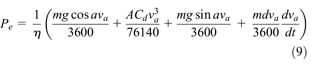
In this study, brushless DC motors were selected as the in-wheel motors, in view of their simple structure, high efficiency, long lifetime, large power at lower velocities, and good controllability. The power of the motor in this study was 25 kW. The largest torque was 160 N m. The highest speed of the motor was 6000 rpm. Equation (9) was employed to calculate the EV power according to the power balance equations for the car traveling. A map of the motor speed and torque is shown in Figure 2.

MAP chart of brushless DC motor.
Where, Pe is the motor power.
The speed of the in-wheel motor can be calculated through equation (10).

Here, nmax is the maximum motor speed, and vmax is the maximum velocity of the EV.
Models of batteries
Ternary lithium batteries were employed as the power batteries; in which, nickel, cobalt, manganese, and lithium can be selected as the materials. The percentage composition of nickel, cobalt, manganese, and lithium can be adjusted according to need. Thus, these batteries have a good safety performance and large capacity. In this simulation, an internal resistance model was employed, in which only an ideal voltage source and internal resistance were used to form the batteries.
The voltage balance equation (equation (11)) can be expressed as follows:

Here, E1 is the open-circuit voltage, U1 is the terminal voltage of the batteries, R1 is the constant battery internal resistance, and I1 is the electric current in the circuit.
The energy balance equation (equation (12)) can be expressed as follows:

Here P is the power of the batteries.
The state of charge (SOC) can be calculated through equation (13).

In the above, SOC0 is the original SOC of the batteries, and CN is the rated capacity.
Simulation and analysis
In the EV model driven by four in-wheel independent motors, the total battery capacity was 75 kW, and the motor power was 25 kW. The other parameters of the EV are listed in Table 1.
Model parameters.

Based on the above motor models, battery models, and so on, simulation models are built, as is shown in Figure 3.
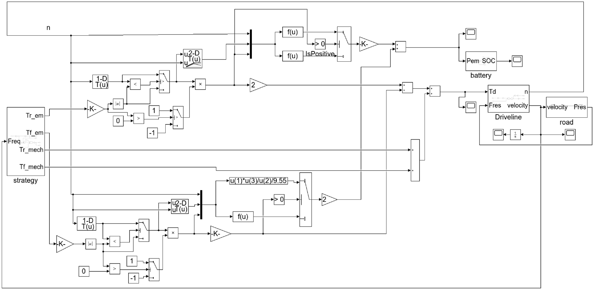
Model of four-wheel drive vehicle.
To verify whether the studied EV could work well, a common city conditions driving cycle (CYC_1015) was selected for the EV working conditions in the simulation. In the simulation, the time of a single working cycle was 660 s, and the highest speed was 70 km/h. The simulation results are presented in Figure 4.

Simulation results of the whole vehicle model: (a) battery level and (b) mileage.
Figure 4 indicates that the studied EV can operate for 20 h and cover 457 km after 110 working cycles. The SOC of the battery is 12% and the electricity consumption, whose curves are linear with respect to time, makes sense in view of protecting the batteries.
When the EV is traveling, the fact that the speed of EV according to the requirements of the working cycle is an important piece of evidence for verifying that the EV can work well.
Figure 5(a) and (b) show the required EV speed of the working cycle and actual speed in the simulation, respectively.

Comparison of key indicators of the whole vehicle simulation: (a) body speed required by working conditions, (b) actual speed of the electric vehicle, (c) motor torque for body requirements, and (d) actual output torque of the motor.
A comparison of Figure 5(a) and (b) shows that the EV speed curves in the simulation can vary based on the requirements of the working cycle, and that the highest speed does not exceed 80 km/h. The actual EV speed curves agree with the required curves, which indicates that the studied EV-driven four in-wheel motors have a good working performance, and can meet the requirements of city life. This also verifies that the built models are correct.
During EV traveling, the torque of the driving motors determines the driving force of the EV. Figure 5(c) and (d) show the required torque curves for CYC_1015 and actual torque provided by the in-wheel motor, respectively. It can be observed from the comparison that Figure 5(d) agrees with Figure 5(c), verifying that the studied brushless DC motor can effectively drive the EV.
Research on control algorithm of brushless DC motor
Models of brushless DC motor
In general, the operation modes of three-phase six-state motors with two-wire conduction and star connections are simple, and exhibit good performance. Therefore, motors with these operation modes were employed in this study. The voltage balance equation (equation (14)) can be expressed as follows:
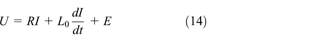
Here, U is the instantaneous value matrix of the stator three-phase voltage, R is the armature resistance, I is the instantaneous value matrix of the stator three-phase current, L0 is the mutual induction of the three-phrase stator winding, and E is the instantaneous value matrix of the three-phase stator back-electromotive force.


At a 360° electric angle, the reluctance of the magnetic circuit does not change with the position of the rotor, and the three-phase winding is symmetrical.
Equations (20) and (21) can be achieved as follows.

In the above, L is the self-inductance of every two windings in the stator.

Here, M is the mutual induction of every two windings in the stator.

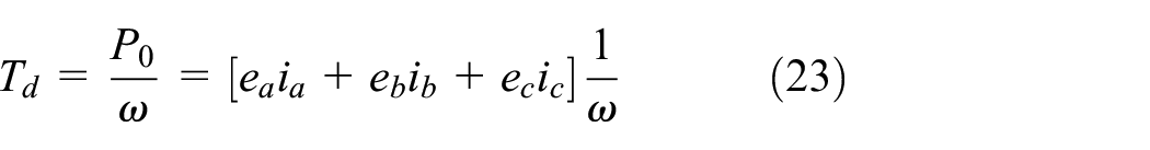
In the above, Td is electromagnetic torque, ω is the mechanical angular velocity of the rotor, and P0 is the motor power.
When the inverter is conducted at an angle of 120° to power the brushless DC motor, the energized conductor in the motor is in the same magnetic field, and the induced electromotive force of each winding can be expressed by equation (24).

Here, N is the total number of conductors, a is the number of parallel branches, B is the magnetic induction intensity, v is the speed at which the wire cuts the magnetic induction line, and l is the length of the conductor.
v can be obtained from equation (25).

Here, n is the rotating speed of the motor, and D is the rotor diameter.

In the above, p is number of pole-pairs, and ф m is the air gap main flux.


In the above, Ke is factor for the electromotive force.
A star connection is employed in the brushless DC motor, and its induced electromotive force comes from a two-phrase winding series connection via the inverter. Therefore, the induced electromotive force Ed of the brushless DC motor can be expressed by equation (29).

The electromagnetic torque Td can be expressed by equation (30).

In the above, Id is the provided square wave current amplitude.
ω can be obtained from equation (31).

Thus, Td can be calculated according to equations (32) and (33).


Here, KT is the torque factor.

The kinematics equation for the rotor can be expressed by using equation (35).

In the above, Tl is the load torque, that is, the sum of the applied mechanical torque and damping torque, and J is the moment of inertia of all of the rotational masses attached to the rotor shaft.


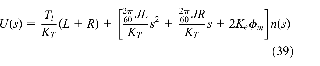
According to voltage balance equation, the following equations can be achieved.
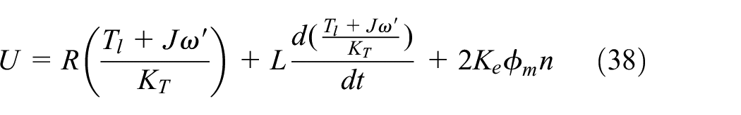
The Laplace transformation is conducted using equations (38) and (39).

Developed whale optimization algorithm-proportional–integral–derivative (WOA-PID) control algorithm
The WOA-PID control algorithm is employed in this study to more effectively control the speed of the motors. A normal WOA is developed for a faster speed of convergence and higher accuracy; then, the developed WOA is used to optimize the factors of PID controllers. The PID parameters determined by experience are relatively limited, the control effect is greatly limited, and the control effect of the PID controller can not be stably guaranteed. By contrast, the PID parameters (kp(Proportional), ki (Integral), kd (Derivative)) solved by the optimization algorithm can ensure the stability and superior control performance of the PID controller. The developed PID controller is used in the motor control system to control the rotation speed of the motor. Thus, the rotational speeds are smoother, and the drivers’ speed objectives can be realized more quickly.24–27 The working theory of the developed WOA-PID control algorithm is illustrated in Figure 6.
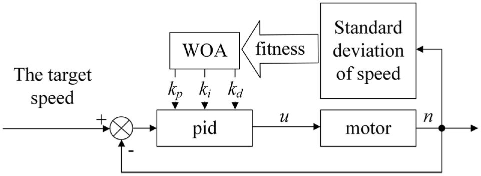
Block diagram of WOA-PID control algorithm.
The WOA is a type of swarm intelligence algorithm whose main idea is to imitate whales’ hunting processes by referring to the surrounding hunt and hunting by using spiral bubbles. The optimum solution is regarded as the prey, and is searched for by referring to the process of whale hunting. The WOA has good solving effects on multi-objective questions. However, the WOA has some disadvantages, such as its poor ability to avoid local optima, low accuracy, and slow convergence rate. In view of the above problems, a normal WOA was developed as follows.
1. Optimize the WOA random parameters r1, r2 in the process of renewing positions.
Chaos theory has been employed widely in swarm intelligence algorithms, in view of its randomness, ergodicity, and non-repetitiveness; thus, the diversity of the original group can be strengthened, and the optimization performance can be enhanced. Compared with random searching, chaos theory can be used to conduct a more comprehensive search in the search space. In this optimization, the values of r1 and r2 are distributed more randomly through the Kent mapping in chaos theory. Then, the ability to avoid local optima can be greatly enhanced by putting the operation into the algorithm. The number of mappings is set so that the ability to jump out of the local optimum can be improved in the early searching, and the entire slow iteration speed can be avoided. The specific mathematical models are as follows.
When the iteration number is smaller than 1/3 of the total number of iterations, the mapping parameter u is set to 0.3.


r 1 and r2 from the mapping are inserted into the computation, and the parameters from the Kent mapping make the calculations more comprehensive.
2. Change the adaptive weight coefficient with iterations. An adaptive weight is employed in the new algorithm and specifically in the early stage, so that the optimal solution in each previous generation has less influence on generating the next generation of populations, which is used as a way to avoid local optima. 28 Then, in the later period, the influence of the optimal solution in each generation gradually increases during the iterations. Thus, the convergence rate and accuracy of the developed algorithm are increased. The adaptive weight coefficient can be calculated by using equation (43).

Here, W is the adaptive weight coefficient in the iteration. The value of q is between 0 and 1; for this developed WOA, when q is equal to 0.5, the WOA can obtain a good result by introducing the adaptive weight. In addition, t is the current iteration number, and MAX_iter is the total iteration number.
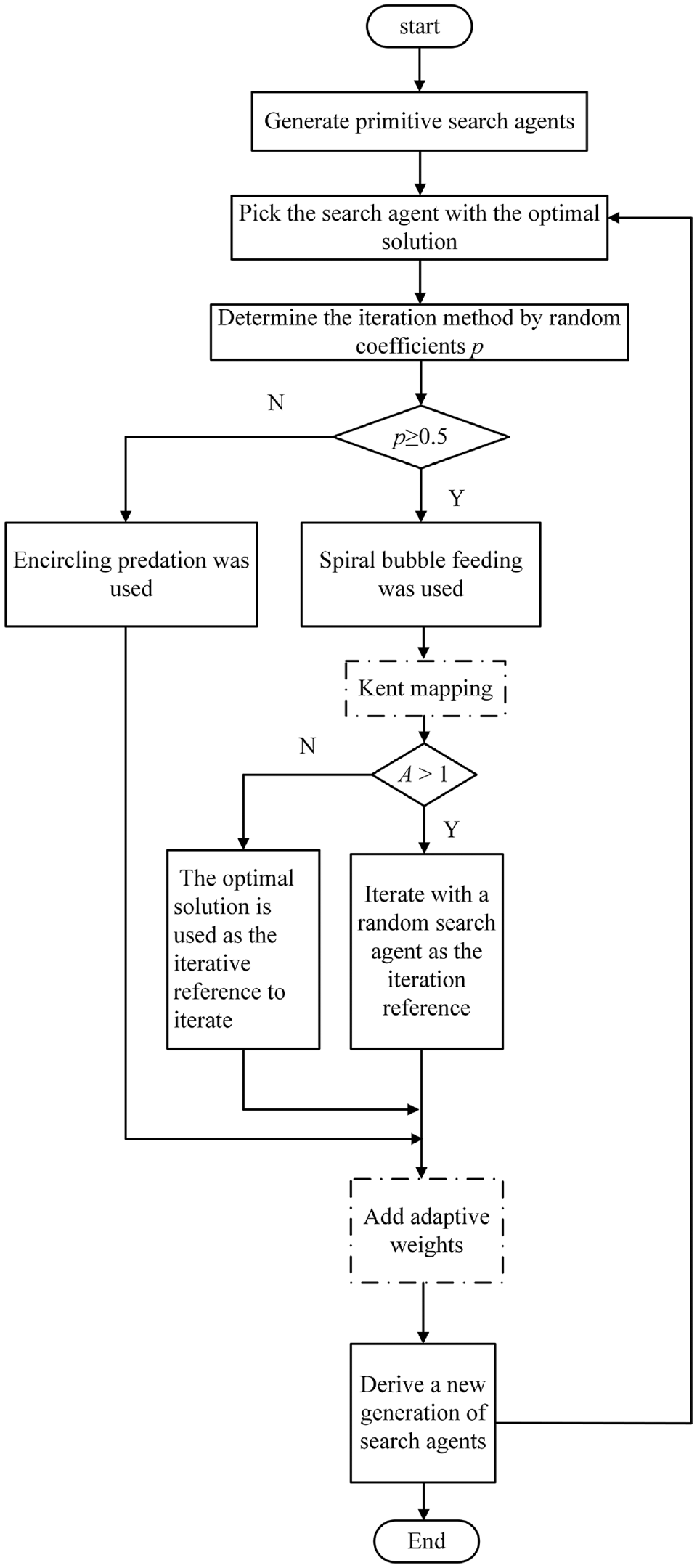
In summary, the optimization method based on Kent mapping enhances the ability to avoid local optima. After introducing the adaptable weight coefficient W in the algorithm, the convergence speed of the developed WOA is improved, and the convergence accuracy is increased. Accordingly, the improved whale optimization algorithm based on Kent mapping and adaptive weights (KW-WOA) is proposed. A flowchart of the KW-WOA is shown in Figure 7.
Block diagram of KW-WOA algorithm.
As is shown in the Figure 7, the kent mapping and the adaptive weight coefficient affect each iteration of the algorithm. The chaotic mapping combined with the three position update methods can ensure the diversity of the population to a great extent, and effectively guide the optimal solution in KW-WOA to move in the direction of higher accuracy. When the number of iterations is sufficient, the optimal solution is also mature to a certain extent, and the convergence speed of KW-WOA is improved by the action of adaptive weights to complete the optimization algorithm solution.
To verify the optimizing ability of the KW-WOA algorithm, unimodal functions and multi-peak functions were employed to test the convergence speed, convergence accuracy, and ability to jump out of a local optimum. All benchmark functions are listed in Table 2.
Description of benchmark functions.
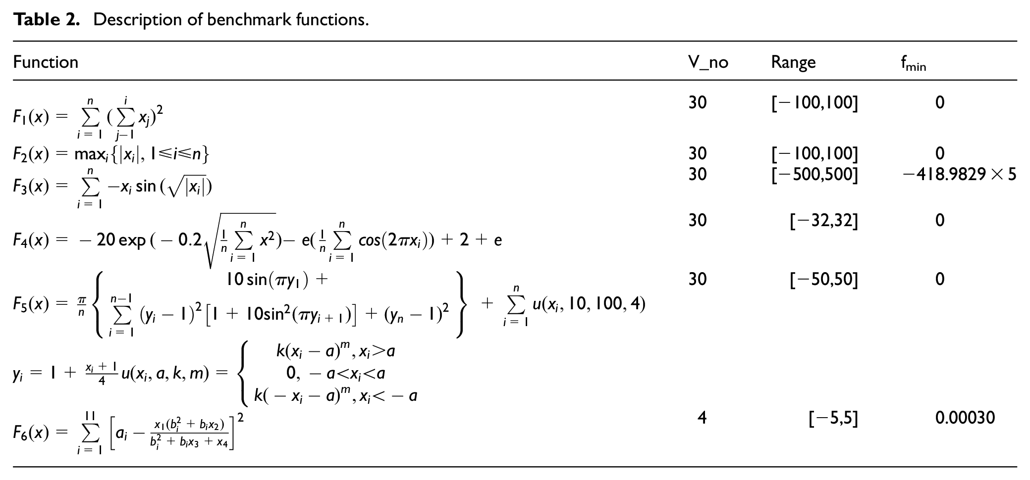
Among them, F1–F3 were unimodal functions, and F4–F6 were multi-peak functions. The testing results are shown in Figure 8, in which the full lines represent the iteration process of the WOA, and the dotted lines represent the iteration process of the KW-WOA.

Algorithm comparison of optimizing F1–F6: (a) algorithm comparison of optimizing tested function F1, (b) algorithm comparison of optimizing tested function F2, (c) algorithm comparison of optimizing tested function F3, (d) algorithm comparison of optimizing tested function F4, (e) algorithm comparison of optimizing tested function F5, and (f) algorithm comparison of optimizing tested function F6.
Figure 8(a) to (f) shows the convergence curves of WOA and KW_WOA for the solution of the benchmark function.
Figure 8(a) to (f) verify the advantages of this development. In the first 1/3 of the iterations, the filial generations are more dispersive, and the convergence speed is comparatively slow to maintain population diversity. However, after 2/3 of the iterations, the convergence speed and accuracy are enhanced, owing to the influence of the adaptable weight coefficient.
From the analysis of the optimization process for the different testing functions, Figure 8(a) to (f) indicate that the convergence speed of KW-WOA is faster than that of WOA for the different testing functions, and the accuracy of KW-WOA is higher than that of WOA.
In order to verify the universality and stability of the KW-WOA, the average values and standard deviation were calculated after 20 solutions, and the results are shown in Table 3.
Comparison of optimization results obtained for the benchmark functions.

It can be seen from the mean values and standard deviations of the multiple solution results that the KW-WOA is more accurate than the normal WOA, indicating that the solution accuracy of the KW-WOA is generally higher. The standard deviation of the multiple solution results is smaller, indicating that the solution results for the KW-WOA are more stable. Thus, it can be proven that the KW-WOA has a faster convergence rate, and a more accurate and stable solution.
The KW-WOA is employed to optimize the PID-controller’s three parameters for the in-wheel motors used by EVs, and the optimized KW-WOA-PID controller is used to conduct the simulation experiments for the driving motors.29–37 The PID parameter values are ranged among [−100,100], the number of iterations is 100, and the population number is set to 30. The obtained KW-WOA based PID controller parameters are: kp = 20.3312, ki = 0.5746, kd = 59.1546 after successful finalization of the optimization process. The simulation curves are shown in Figure 9(a) to (c), in which the dotted dashed lines, broken lines, and full lines are the motor speed curves of the open-loop control, PID controller as optimized by the normal WOA, and KW-WOA-PID controller, respectively.

Simulation curves of motor speed under different control strategies: (a) curves of motor speed variation for a target speed of 200 rpm, (b) curves of motor speed variation for a target speed of 400 rpm, and (c) curves of motor speed variation for a target speed of 600 rpm.
Figure 9(a) to (c) show that when the target speed is set at a low speed of 200 rpm, medium speed of 400 rpm, and high speed of 600 rpm, the maximum overshoot of the motor speed controlled by the improved KW-WOA-PID approach is significantly lower than that with the normal WOA, as it decreases by more than 4%. Thus, it is proven that the KW-WOA-PID control can effectively reduce the maximum overshoot when the motor speed changes, and that it improves the relative stability of the system. The adjustment time for the motor speed as controlled by the KW-WOA-PID control is more than 28% lower than that without, proving that the KW-WOA-PID control can effectively reduce the adjustment time for a motor speed change, and improve the response speed of the control system.
To more easily determine the control effects, the responses of the motors were calculated, and are shown in Table 4.
Transient response criteria for different controller type.

Table 4 indicates that the designed KW-WOA-PID controller achieves the expected control effects. Under the control of the KW-WOA-PID controller, EVs can be driven based on the driver’s intention, and the automotive handling performance and safety performance are greatly enhanced.
Bench tests of the in-wheel motor control system
Construction of test rig
An STM32F103ZET6 was employed as the CPU of the in-wheel motor control system, an insulated-gate bipolar transistor was employed as the power tube of the three-phase full bridge circuit, and a PS21A7A was employed as the driving chip. A 48 V DC battery pack provided power for the in-wheel motor. A brushless DC motor with Hall sensors was employed as the in-wheel motor. The HD-200 speed sensor manufactured by Suzhou Durst Automation Equipment Co. Ltd. was used to measure the rotational speed of the motors in the tests. The CZ-20 magnetic powder brake manufactured by Suzhou Durst Automation Equipment Co. Ltd. was used as the load of the driving motor.
The flowchart of the in-wheel motor test is shown in Figure 10.
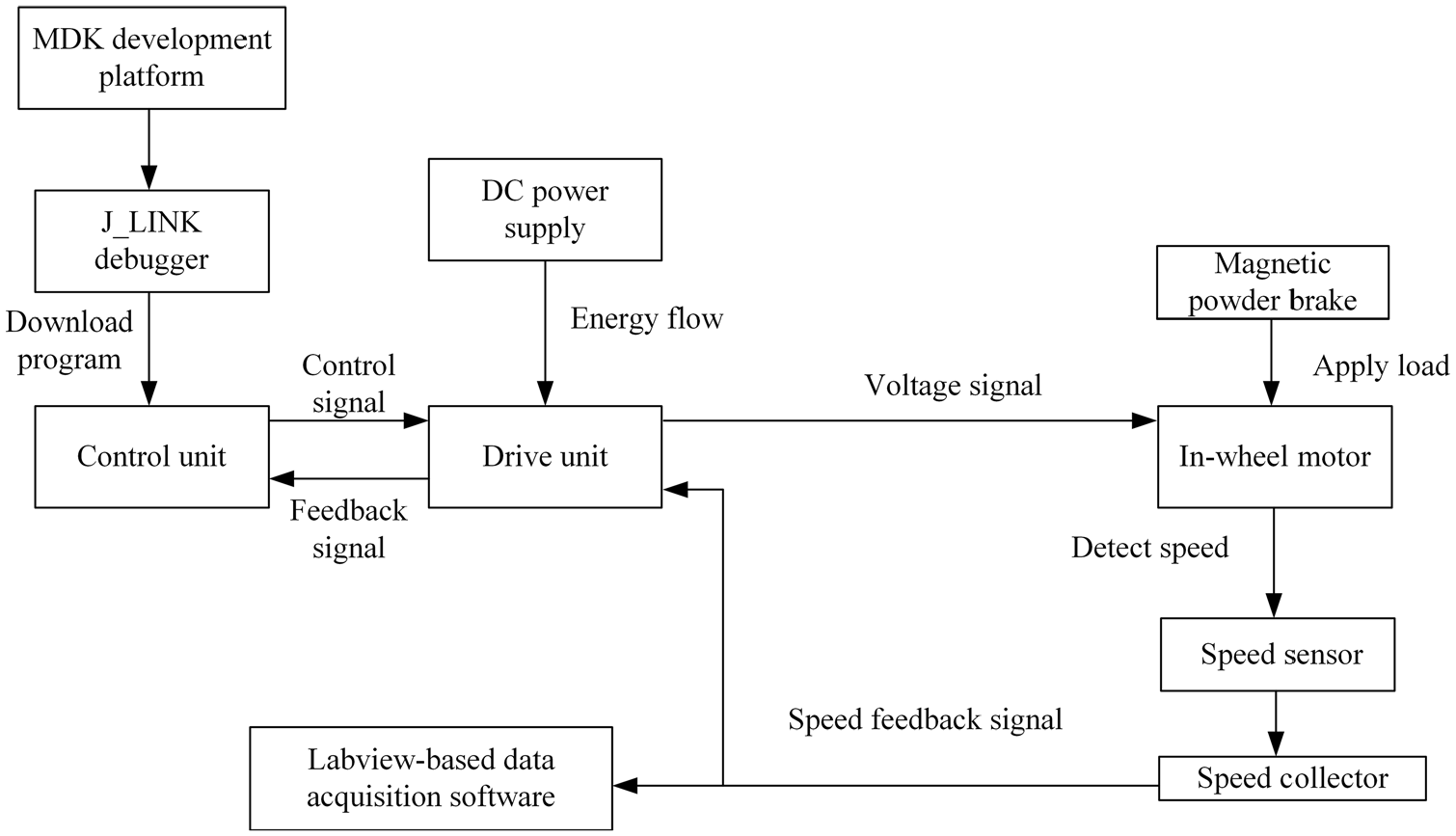
The flowchart of the in-wheel motor test.
To detect the control effects of KW-WOA-PID clearly, the motor rotational speed was measured, and Labview software was employed to compile the speed-measure programs. The developed test rig is shown in Figure 11.

Test rig. The test rig includes: (a) MDK program interface, (b) speed Indicator, (c) air switch, (d) brushless DC motor, (e) driver board, (f) speed sensors, (g) main control board, (h) magnetic powder brake, (i) J = LINK debugger, and (j) 48V DC power supply.
The key step of motor control is mainly the control of the interrupt program. The interrupt program used this time first jumps into the interrupt from the main program, then latches all kinds of data, collects the voltage signal, detects the position through the Hall sensor, and then calculates and adjusts through the PID controller, and the voltage is adjusted to output six PWM waves. Control the output speed of the drive, return to the main program and then cycle the above process.
Testing results and analysis
To check whether the in-wheel motor used in the EVs could work well, bench tests were conducted under the working conditions of 200, 400, and 600 rpm, respectively.
The load torque provided by the magnetic powder brake was 3 N m, and the testing results from the brushless DC motor as controlled by KW-WOA-PID were compared with motors controlled by a normal WOA-PID controller, an empirical PID controller, and an open-loop controller. The testing results are shown in Figure 12(a) to (c).
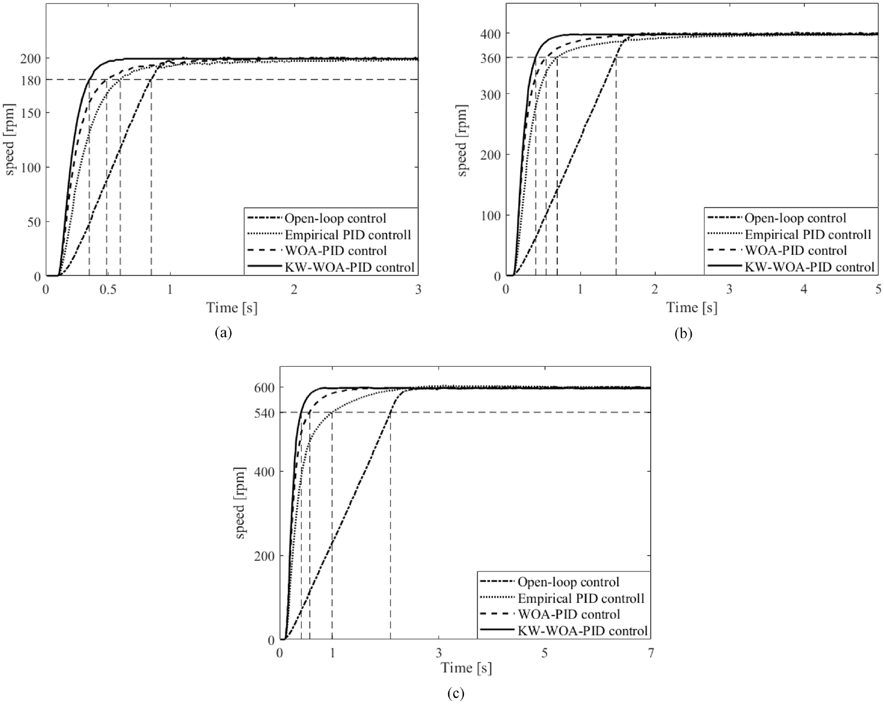
Experimental curves of motor speed under different control strategies: (a) curves of motor speed variation for a target speed of 200 rpm, (b) curves of motor speed variation for a target speed of 400 rpm, and (c) curves of motor speed variation for a target speed of 600 rpm.
Figure 12(a) to (c) indicates that the curve rise time and settling time of the motor speed controlled by the KW-WOA-PID are shorter than those controlled by the three other control algorithms in the working conditions for low, middle, and high speeds. It can be discovered from the Figure 12 that the KW-WOA optimized controller can make the motor respond faster, and the rise time and adjustment time of the speed change are significantly optimized. This means that the proposed optimization algorithm can effectively optimize the controller, thereby improving the control effect of the controller on the motor, and finally achieving the purpose of improving the steering stability of the electric vehicle.
The transient response data of the brushless DC motor under the different control algorithms were calculated, and are shown in Table 5.
Transient response criteria for different controller type.

As can be seen from Table 5, the motor speed rise time under the control of the KW-WOA-PID is at least 22.4% less than that of the motor speed under the control of the normal WOA-PID, and the settling time is reduced by more than 21.1% in the full speed range required by the working conditions. The KW-WOA-PID controller evidently improves the motor response speed when the speed changes, and reduces the time for the motor to reach the target speed and the time required to stabilize the motor speed. Electric vehicles are faster to meet the demands of drivers.38–41
It can be seen from the analysis that under the control of the KW-WOA-PID, the response time for the speed is faster, and the driving motor can reach the target speed in a shorter time under the working conditions of low speeds, middle speeds, and high speeds. Moreover, the stability is higher than those of motors controlled by other algorithms. Thus, the developed KW-WOA-PID helps cars driven by in-wheel motors to change their speeds more stably, and the safety and handling performance of EVs can be significantly enhanced.
Conclusion
This paper proposes an improved whale optimization algorithm PID (KW-WOA-PID) control algorithm suitable for the speed control of the in-wheel motor of the four-wheel drive electric vehicle. Firstly, the control requirements of the four-wheel drive electric vehicle on the speed of the drive motor are modeled and analyzed. Then, the mathematical model and simulation model of the in-wheel motor are established, and the iterative process of the conventional whale optimization algorithm are optimized by the adaptive weight coefficient and kent mapping, so as to design the new KW-WOA-PID control algorithm. Simulation test and bench test show that under the control of the new algorithm, the in-wheel motor has a faster response speed and higher control accuracy, which improves the safety and handling stability of the vehicle. This study uses four-wheel drive electric vehicle model and brushless DC motor model on the basis of referring to other scholars’ proposed models for modeling, so the research has solid theoretical basis. The research on the optimization method of PID controller by other scholars ensures the feasibility of the experiment. Through the comparison of various algorithms by other scholars, WOA was selected as the research object because of its superiority. KW-WOA was introduced into the brushless DC motor PID control system and achieved excellent results.
Footnotes
Handling Editor: Chenhui Liang
Declaration of conflicting interests
The author(s) declared no potential conflicts of interest with respect to the research, authorship, and/or publication of this article.
Funding
The author(s) disclosed receipt of the following financial support for the research, authorship, and/or publication of this article: This work is sponsored Key Research and Development Projects in Anhui Province (2022a05020007), by the National Natural Science Foundation of China (51605003) and undergraduate teaching quality improvement plan project of Anhui Polytechnic University (Grant no. 2021jxtd02).