
Abstract
Electric vehicles are becoming more and more prevalent, especially with major manufacturers announcing that they will be focusing on electric or hybrid vehicles in the future. This article describes an object-oriented approach to a vehicle model using Python 3. This approach allows for flexibility of vehicle design. The key parameters were input to define the specific vehicle for validation, in this case a Nissan Leaf. It is anticipated that this flexibility will lead to rapid exploratory design of vehicle variants, such as four-wheel drive, independent wheel drive and multiple electrical sources. The model had its objects individually validated before the whole vehicle was verified against common drive cycles and a real-world drive in the United Kingdom recorded using an On-board Diagnostics (OBD2) Bluetooth dongle.
Keywords
Introduction
Object-oriented programming (OOP) has many benefits over other programming paradigms such as imperative, functional or procedural paradigms with respect to enhancing the functionality and usability of a vehicle model.1–4 Many processor architectures are natively capable of running compiled C++ code 5 unlike a multi-paradigm environment such as MATLAB 6 which generally requires an operating system. This opens the door to opportunities of running the vehicle model on small embedded systems in vehicle in future projects to allow for hardware-in-the-loop (HIL) testing and model predictive control (MPC).7–10 It is critical for advanced software to be usable by others without a deep knowledge of the language, style or structure of the software in order to enhance usability. 11
Furthermore, OOP gives the software for a vehicle model some key functionality benefits. Encapsulation allows for certain portions of data to be protected from external manipulation. This encapsulation allows for greater certainty that the model is performing correctly and that data have not been manipulated by code trying to force a desired output. It also allows for greater decoupling of different data structures, leading to a modular structure to the full model which utilises composition and inheritance. Composition allows for objects to contain other objects in a ‘has-a’ methodology. For example, a powertrain has a motor, battery and gearbox (among others) and therefore receives a reference to these other objects within the model so it can access their data in a controlled manner. Inheritance allows for an ‘is-a’ relationship to be created. For example, the battery and the motor are both electrical devices so they can inherit the ‘ElectricalDevice’ abstract base class. From a user friendliness point of view, it ensures that any access to the voltage of the motor is done in the same way as the voltage of the battery, for example. It also greatly reduces the duplication of code which can lead to excessive debugging. Inheritance goes hand in hand with polymorphism which in turn allows for reduced memory usage and quicker development time. 12
On the road today are several different types of electric vehicles. They are often loosely categorised as hybrids; however, this general umbrella term is not specific enough to describe this work. Any vehicle which has a mechanical connection between an internal combustion engine (ICE) and the wheels is not considered in this model (although could be included in the future) meaning that only electrical drive is explored. However, the model does allow for an ICE to be used as a generator to convert fuel into electrical energy in vehicle as it can be easily compartmentalised in the code as a type of an ElectricalDevice object (utilising inheritance). Similarly, a hydrogen fuel cell may also be represented and used as a range extender or as a primary electrical supply instead of a battery, for example.
In this article, we will only consider an electric vehicle with a battery as the only energy store on the vehicle, in order to validate the model and provide a suitable foundation for future work. It is the authors’ intent to use this model to perform explorative research on different vehicle powertrain design configurations and their associated performance, such as independent wheel drive, four-wheel drive (4WD) with one motor and 4WD with one motor per axle, to name a few general ideas.
The structure of the code is given to allow for replication, a demonstration of the programming methodology used and the robustness of the code. To understand and prove the model’s limitations, a robustness study and a validation study were conducted using real-world data.
Model
The OOP language being used for the vehicle model is Python 3.13,14 This is a high-level interpreted language, removing the need for length and complicated compilations to run the code. Python has a large standard library, automatic memory management and is cross-compilable into C++ code for embedded systems making it ideal for this research. Furthermore, it is open-source and freely available.
Traditionally, MATLAB is used for engineering and science programming; however, this software is not ideal for low-power embedded systems.15,16 With a view to running HIL testing onboard an electric vehicle, it is logical to aim for the lowest power approach to reduce any impact the computer has on vehicle range. Rather than cross-compiling from MATLAB to an embedded system, which is difficult to do, a native Python-to-C++ cross-compiler may be used (e.g. Cython).
High-level classes
In Python, the vehicle is defined as an interface class as in Figure 1. This structure allows for all vehicles to have the same methods at the higher level, that is, a global interface to interact with the vehicle without needing to know the specifics of what type of vehicle it is or how it works. For simplicity, the only methods that are required by higher levels are an ability to demand a velocity and the ability to run the model and update the output at each time step. A key advantage of this method is that multiple vehicles can be spawned into the environment with the same or different parameters allowing for a study of a fleet of vehicles.
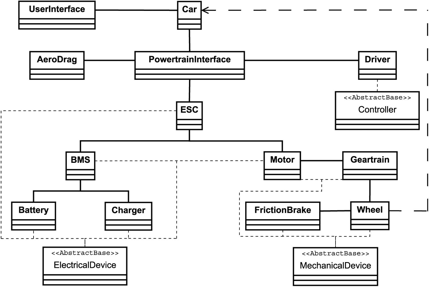
Software schematic showing the various objects of the model, each being independent blocks of code. Of particular note are the abstract base classes which define the linking structure between the higher level classes. This methodology is native to OOP and provides simplicity when changing the vehicle configuration to, for example, four-wheel drive or independent wheel drive.
Inherited by the car class are the aerodynamics and a powertrain. The aerodynamics only required velocity at each time step since the model is two-dimensional (2D). It then outputs a drag force. The powertrain requires the velocity at the last time step and the demanded velocity at this time step; however, this method can be improved by adding future demands to anticipate a change occurring, that is, feed-forward control. The powertrain outputs a force which is summed with the aerodynamics force and the new velocity is calculated using Newton’s first and second laws.
The powertrain is a dynamic class that can be instantiated in different ways based upon the objects that get passed to its constructor. For example, a single motor object connected to the two front wheels may be passed to the powertrain to define a front wheel drive car like the Nissan Leaf. However, the user may pass the constructor four motors, each only connected to one wheel to simulate a four-wheel independent drive car.
Low-level classes
Beneath the powertrain in the model hierarchy are the motor, wheel, battery, friction brakes, transmission, road and the electronic speed controller (ESC) classes.
The motor and battery both inherit the abstract base class of an electrical device. In this article, a battery is considered but any electrical device could be looked at in the future such as an ICE driving a generator, fuel cell or a supercapacitor. Furthermore, these can be hybridised. 17 Again, this allows for various methods and properties to be defined as common between all electrical devices, such as voltage, cumulative energy and power limit. All of these data are available on each iteration allowing for any of these data to be plotted to understand device specification requirements.
Similarly, the motor, wheel, transmission and friction brake all inherit the abstract base class of a rotational, mechanical shaft. This is to permit setting torque limits and to understand how the torque is being transferred around the system. It is notable that here the motor is inheriting two base classes; this is called multiple inheritance.
Finally, the ESC and separate traction control module both inherit from a proportional–integral–derivative (PID) controller abstract base class. The whole speed management system is constructed in a nested logic manner to allow the motor and friction brake to have their own independent control systems with rate limits and saturation limits. The two are controlled by the ESC which attempts to reduce the error between the velocity demand from the drive cycle and the actual vehicle speed. The traction control system may have different modes, such as economy, comfort, sport and race, as is seen in many vehicles today, and intercepts the velocity demand signal before it reaches the ESC. It then may amplify or reduce the error or apply a derivative-based ramp to suit the different driving modes. It is notable that the model can bypass the cruise controller and send signals directly to the motor and brake to mimic a driver controlling the vehicle with pedals.
User interface
The user interface (UI) is the main runtime code that the user can configure to meet the needs of the simulation. Pre-defined vehicle parameters can be passed from the UI into the high-level car class constructor to instantiate an object representative of a Nissan Leaf, for example. Furthermore, these pre-defined values can be modified to create subtle or extreme changes to the object in order to perform exploratory research, for example, halving the battery size, reducing motor power or making the car 4WD. Finally, a whole custom car could be defined or iterated to produce the specification of vehicle required to meet certain requirements such as range, weight and power.
The UI is also responsible for interrogating the drive cycle that the user wishes to follow and analysing which point in time, with respect to the system clock, that the model is in. This non-deterministic approach means that faster computers will ultimately produce more data points per second of drive cycle time than the slower ones. It also means that the model runs in real time, opening the door for future HIL testing. Different drive cycles can be attached to different vehicle objects, so multiple vehicles can be simulated simultaneously while driving different cycles, or alternatively a drive cycle can be repeated indefinitely (or until the battery is fully discharged).
Outputs from the UI are typically time series datasets of any user-accessible property of any object within the model which are typically presented as comma-separated value files or graphs.
Vehicle configuration
As has been shown, the structure of the object-oriented approach allows for linking of different classes to be changed, that is, there are fewer dependencies and therefore fewer changes to the code required to alter the setup of the model. For example, extra motor objects can be spawned, perhaps one per wheel, to simulate independent wheel drive, or the single motor can be linked to all four wheels to provide a more traditional 4WD setup. Alternatively, two motors could be used, one on each axle to provide a distributed 4WD setup. The idea in this example is that it may be preferred to design a vehicle with no motor bay to maximise the interior space, so smaller motors in the wheel hubs would be ideal. The model will assist in explorative design to assess the performance of the vehicle in this configuration.
Verification
Module
This section of the article describes the model verification, that is, the confirmation that the code has been correctly implemented and is performing as expected. This includes each of the individual objects within the model and the linking between objects to become the full model.
Figure 2(a) shows a verification of the wheel object. This test shows the stability and accuracy of the wheel under low acceleration and full power, followed by increasing brake torque for deceleration. For this test, the effects of aerodynamic drag, vehicle inertia and wheel slip were ignored as these effects require feedback from a higher level object in the overall model to calculate. For this test, the whole vehicle model was not included in order to ensure that the only effects seen in the verification are those caused by the wheel and its directly coupled components of the drivetrain.

Verification of powertrain: (a) Wheel object verification achieved by simulating a single wheel, motor and brake without any higher level linking. The wheel does not decelerate noticeably once spooled up as it is freewheeling in space, and it only has inertia in this test. (b) Powertrain object verification achieved by simulating two driven and two non-driven wheels which all have independent brakes and no aerodynamic drag or higher level linking. The powertrain is slightly overdamped resulting in no overshoot.
Following the verification of the wheel model, the whole powertrain needed to be verified. This includes both powered wheels and the two non-driven wheels (which includes brakes on each wheel). It can be seen from Figure 2(b) that very little force is required by the motor for maintaining a constant speed. This is to be expected when aerodynamic drag is omitted. The speed controller is also included in this test to ensure its basic ability to control the motor and brakes.
Controller
Figure 3(a) shows the speed response to the step input of 25 and 100 km/h. Both show that there is an overshoot of

Controller robustness: (a) Velocity step change showing that the controller is slightly underdamped at a maximum power step input resulting in an acceptable overshoot of
The speed control system, imitating the driver’s acceleration and brake pedal positions, must be robust enough to not become unstable during normal operation. The control system has been tested using step inputs, impulses, ramps and sine waves. Figure 3(b) shows that there are minimal phase lag
Typical controller testing has also been conducted at high- and low-frequency sine wave inputs, impulse and various steady-state conditions. The results have shown that the simple PID controller is robust and able to take a velocity demand and control the motor/brake in order to meet this demand in a realistic way with respect to the Nissan Leaf. The results shown have been validated against the authors’ Nissan Leaf; however, this is discussed in detail later.
Whole vehicle
The final phase of verification is to link all the various objects into the whole model of the Nissan Leaf. This was done using the structure shown in Figure 1 and the data from Table 1. It is well known that the Nissan Leaf meets various drive cycle standards, for example, New European Driving Cycle (NEDC) and Federal Test Procedure (FTP)-75. These drive cycles were used as inputs to the vehicle model and are shown in Figure 4(a) and (b), respectively. The points of interest here are the agressive acceleration zones of the FTP where

Whole vehicle verification using common standardised drive cycles as velocity inputs: (a) New European Driving Cycle (NEDC) and (b) Federal Test Procedure (FTP)-75 US Environmental Protection Agency Federal Test Procedure.
Vehicle data.

Measured from the author’s 2016 Nissan Leaf.
Validation
Following verification, the vehicle model must be validated against real-world data to ensure that it is an accurate representation of an electric vehicle. In this article, the authors’ Nissan Leaf is used to validate the model. Figure 5 shows a

Real-world comparison–real-world drive from Birmingham to Loughborough, UK. The car velocity data were captured using an OBD2 dongle and then fed into the model as a velocity demand. Phase lag is
Nevertheless, the variance between the setpoint and modelled velocity is less than
Conclusion
This article has presented a flexible new electric vehicle model which can be easily reconfigured to any electric vehicle using the parameters in Table 1. The model was validated using a 2016 Nissan Leaf and written in Python 3.
Using the programming paradigm of object orientation, the vehicle model is configurable in its setup. For example, the Nissan Leaf, front wheel drive, single-motor setup can be extended to 4WD with a gearbox coupling or independent motors on each wheel. This encourages some exciting future work into specification optimisation for different variants of the Nissan Leaf or other validated vehicles using this model.
Verification included an evaluation of each object within the model both independently and with linked dependencies to ensure an accurate representation of the real world. The model was then validated using a real-world drive between Birmingham and Loughborough, recorded by the means of an OBD2 Bluetooth dongle connected to the authors’ Nissan Leaf. The validation was acceptable and showed a phase shift of under
Footnotes
Handling Editor: Yong Chen
Declaration of conflicting interests
The author(s) declared no potential conflicts of interest with respect to the research, authorship and/or publication of this article.
Funding
The author(s) disclosed receipt of the following financial support for the research, authorship and/or publication of this article: This work has been supported by EPSRC (EP/M009394/1).