
Abstract
In this paper, a seven-stage high pressure centrifugal pump for water injection was taken as the research object. The steady state full flow field was numerically simulated by unstructured grid and Renormalization Group (RNG) k-ε turbulence model, and the results were verified by experiment. The flow characteristics of each flow passage component in the centrifugal pump under rated flow condition were analyzed, and the influence of wear-ring clearance flow on the full flow field was studied. The entropy production theory was applied to compare the distribution law of full flow field with and without wear-ring clearance at rated flow. The range and magnitude of the main energy loss in the pump were quantitatively analyzed. The results show that the guide vane area has the highest entropy production, which is the main energy loss part of the centrifugal pump. The existence of wear-ring clearance increases the entropy production of full flow field and has an adverse effect. The impeller wear-ring clearance has a greater influence on the full flow field than the guide vane wear-ring clearance.
Keywords
Introduction
Multi-stage centrifugal pumps are widely used in petrochemical, energy and other fields due to their advantages of large head and high efficiency. Designing a multi-stage centrifugal pump with high performance, low noise and low energy consumption is the goal that engineers have strived for. 1 Many researchers focus on the improvement of impeller performance as it is the central working part. In the study of the internal flow characteristics of centrifugal pump, the wear-ring clearance is an important factor that cannot be ignored. As shown in Figure 1, its existence will not only produce volume loss, but also change the internal flow structure of centrifugal pump, which has an important effect on the overall performance and shafting vibration of centrifugal pump.2,3 The previous research usually focuses on the main flow field and simplified the effect of wear-ring clearance on the pump as a scale factor due to smaller size, more complex flow and difficulty of experimental research. 4
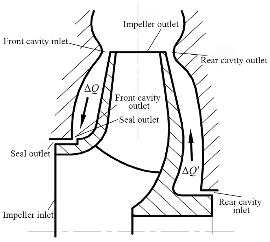
Schematic diagram of clearance flow field of centrifugal pump. 5
Diewald and Nordmann 6 used the finite element method to numerically calculate the internal clearance leakage flow and its influence in a multi-stage pump, and compared it with the existing impeller leakage analysis models. Jiang et al. 5 used CFD method to analyze the influence of different clearance inlet circumferential velocity and clearance width on volume loss in multi-stage pump, and found that the volume loss increases with the increase of clearance width. The study of Jia et al. 7 found that the improved efflux angle of the wear-ring clearance could effectively weaken the impact disturbance of the leakage flow in the wear-ring clearance to the main flow at the inlet. Xianfang et al. 8 studied the effect of front and back wear-ring clearance on the performance change of a pump by test and numerical simulation. The test results show that the head and efficiency of pump decrease by 3.56% and 9.62% respectively at 1.0Dd due to the wear-ring abrasion. Yan et al. 9 studied the wall wear law of the centrifugal pump under different wear-rings clearance through the McLaury wear model. The wear of impeller and volute first increase and the decrease with the increase of clearance.
The above literatures mainly studied the internal flow characteristics of the centrifugal pump from the aspects of wear-ring clearance width, efflux angle, and so on. There are relatively few studies on analysis of energy loss of multi-stage centrifugal pump considering wear-ring clearance. For the analysis of energy loss, the traditional approach is to obtain the range and magnitude of hydraulic losses indirectly through the distribution of pressure and velocity fields in the internal flow field,10–12 though it hardly provides any intuitive access to the specific areas where the energy loss occurs. 13 The application of entropy production theory is regarded as an effective method on the energy loss analysis of centrifugal pump because it bears the property of directly characterizing the intensity of local energy loss. Huang and Li 14 analyzed the hydraulic turbine flow field based on the entropy production theory, accurately solved the position and magnitude of the hydraulic loss in the flow field, and analyzed the reasons for the large entropy production through the details of the flow in the pump. Zhang et al. 15 applied the theory of entropy production to study the flow loss of a single-stage side channel pump, and analyzed the location and distribution characteristics of the hydraulic loss of the pump. Guan et al. 16 analyzed the energy loss of the double-suction centrifugal pump through the entropy production theory. The results indicate that the difference in total entropy production under different flow rates is mainly affected by the entropy production in the main flow region, and the entropy production of volute has the greatest effect on the entropy production in the main flow region. To reduce the operating energy consumption of large vertical centrifugal pump, Yang et al. 17 proposed a matching optimization on hydraulic components and used entropy production theory to visually analyze the energy loss. Hou et al. 18 numerically used the entropy production method to evaluated the energy loss in a centrifugal pump system and found that the central regions of entropy production are located in the front edge near the suction side, the volute tongue, and the trailing edge.
In summary, many of the study focus on the energy loss analysis of single-stage centrifugal pump or other hydraulic machineries through entropy production theory. There are few studies on analysis of internal flow and energy loss in multi-stage high pressure centrifugal pump for water injection considering wear-ring clearance. In this paper, the flow characteristics of each flow passage component in a multi-stage centrifugal pump under rated flow conditions were analyzed numerically, and the influence of wear-ring clearance on the full flow field was studied. The entropy production theory was applied to compare the distribution law of full flow field with and without wear-ring clearance at rated flow, and the range and magnitude of the main energy loss in the pump were quantitatively analyzed.
Numerical simulation and test methods
Computational model
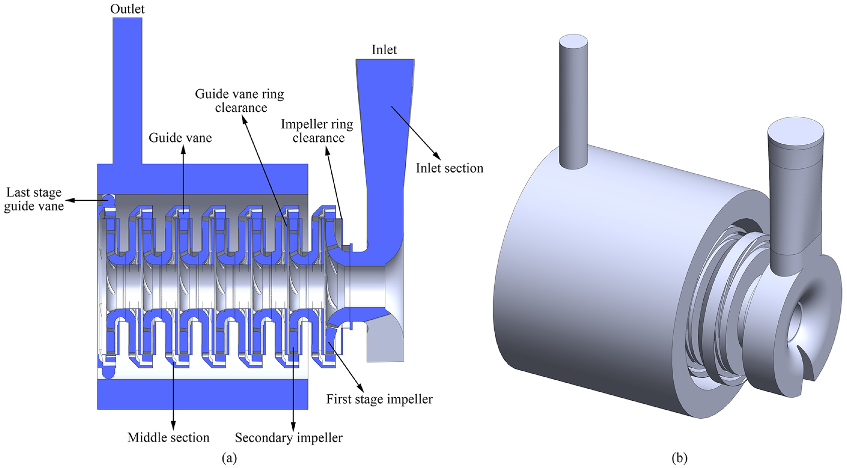
As shown in Figure 2, the computational model in this paper is a seven-stage high pressure water injection centrifugal pump, and its main performance parameters are shown in Table 1. The main flow passage components of the centrifugal pump include suction section, impeller, guide vane, intermediate section, outlet section and other parts. It should be noted that impellers 2–7 are secondary impellers, and the parameters are completely the same. The difference lies in the different angles installed on the rotor. Impeller 1 is the first stage impeller. Compared with the guide vanes of other stages, the last stage guide vane has no intermediate section component and anti-guide vane flow channel, which increases the outlet flow channel.

Multi-stage high pressure water injection centrifugal pump.
Main performance parameters of multi-stage centrifugal pump.

There are wear-ring clearances at the impeller and guide vane of the multi-stage centrifugal pump, which the sizes of them are shown in Figure 3. The influence of these clearances on the pump is often simplified to scale factor due to small size. In this paper, the full flow field model of multi-stage centrifugal pump is based on the main flow field model with the addition of the impeller and guide vane wear-ring clearance. The fluid field of each section in the centrifugal pump was extracted and assembled by SpaceClaim and SolidWorks software. Finally, the full flow field calculation domain of multi-stage centrifugal pump including the wear-ring clearance was obtained as shown in Figure 4. The existence of the wear-ring clearance makes the structure of the fluid domain more complex and also puts forward higher requirements for mesh division.

The wear-ring clearance sizes of centrifugal pump: (a) impeller 1, (b) impeller 2, and (c) guide vane 1.
Full flow field calculation domain of centrifugal pump: (a) axial section and (b) axonometric.
Control equations and boundary conditions
In this paper, the computational fluid domain material was set to water, and the physical parameters are shown in Table 2. In practice, the internal flow field of centrifugal pump is typical turbulent flow with large curvature of flow interface. Considering the cost and accuracy of calculation, the control equation and turbulent model selected here are three-dimensional Reynolds time-average N-S equation and Renormalization Group (RNG) k-ε turbulent model, respectively. 19
Physical parameter table of centrifugal pump conveying medium.

Three-dimensional Reynolds time-average N-S equation is as follows:
Continuity equation:

N-S equation:
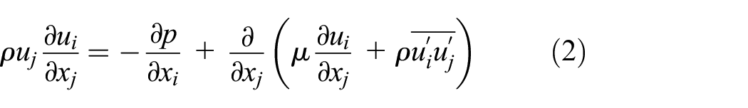
Where
RNG k-ε turbulent model is described as follows:


Where ui denotes component of fluid velocity along i direction, k denotes turbulent kinetic energy, αk and αε denotes reciprocals of effective Prandtl number, Sε and Sk is user-defined, Cp denotes specific heat capacity, ε denotes turbulent dissipation rate, Gk denotes turbulent kinetic energy generated by laminar velocity gradient, Gb denotes turbulent kinetic energy generated by buoyancy, and YM denotes the contribution of fluctuating expansion to the total dissipation rate in compressible turbulence. C1, C2, C3, η0, and β are constant.
CFD software Fluent was used to calculate the full flow field of centrifugal pump. In order to ensure the accuracy of numerical simulation, the setting of boundary conditions needs to be matched with actual test data acquisition methods. The boundary conditions of pressure inlet and mass flow outlet were used here as follows: The inlet surface of centrifugal pump inlet section was set as pressure inlet condition with hydraulic diameter of 40 mm and turbulent intensity of 5%. The outlet surface of centrifugal pump outlet section was set as mass flow outlet boundary condition. All over-flow areas were set as fluid computational domain. The rotating reference frame was used to set the impeller area as the rotating domain with rotating speed of 2980 rpm and others as stationary area. Interface boundary was set between rotating area and stationary area to transfer data between them. All remaining boundary conditions were set as non-slip wall conditions and the standard wall function was used to solved the near wall region.
The type of solver chose pressure basis and steady-state calculation with consideration of gravity acceleration. Pressure-velocity coupling format was set to SIMPLEC algorithm in solution algorithm, spatial discrete settings remained default, and convergence residuals were set to 1 × 10⁻⁵.
Meshing and mesh independence verification
The internal flow channel structure of multi-stage centrifugal pump studied in this paper is complex, and the wear-ring clearance is quite different from the impeller in size, which makes meshing more difficult. Therefore, the ANSYS Mesh software was used to partition the unstructured grid of the whole flow field. The tetrahedral grid was selected for the type of mesh. The curvature and proximity size functions in the software were used to refine meshes in places with large curvature and narrow areas, and the number of global meshes was adjusted by adjusting the mesh correlation and the maximum mesh size in the software.
In order to verify the grid independence, this paper divided six groups of grids with different numbers, and numerical calculations on the full flow field computational domain with different grid numbers were carried out. Then the predicted head was obtained through post-processing and error analysis was carried out with test head (285.3 m) to select the optimum grid number, as shown in Figure 5. To balance the calculation accuracy and efficiency, the final number of grids in the full flow field was determined to be 50,305,241. In addition, the influence of wear-ring clearance mesh size on the calculation results was also analyzed, as shown in Table 3. It was refined by controlling the clearance mesh size, and the final clearance mesh element size was controlled at 5e-3 m. The partitioned grid and local refinement of the full flow field of centrifugal pump are shown in Figure 6. The average quality of the overall grid is 0.82, which meets the calculation requirements.
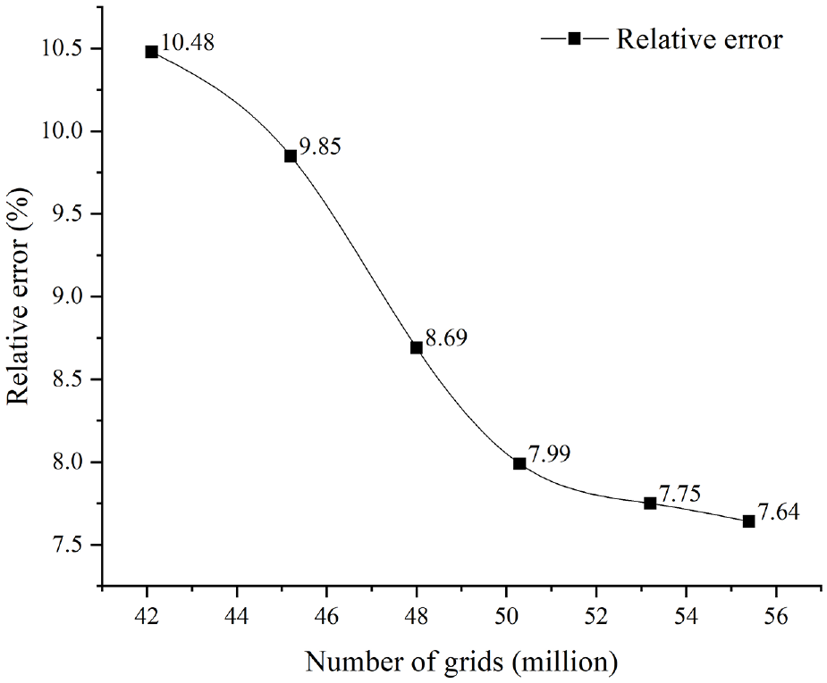
Grid independence verification.
Influence of the wear-ring clearance grid size on the calculation results.


Full flow field meshing and local refinement: (a) full flow field, (b) impeller, (c) guide vane, and (d) wear-ring clearance.
Entropy production theory
Entropy production refers to the characteristic parameter used to describe irreversible energy loss due to heat transfer and fluid viscosity. The location and magnitude of energy loss can be captured in detail by entropy generation theory, and then the flow characteristics in the fluid can be analyzed. The ability to visualize energy and hydrodynamic properties is an advantage of entropy production theory over traditional methods. 20 The wall entropy production was not considered in this paper.
For turbulent flow, the entropy yield S consists of two parts: one is caused by the average velocity, and the other is caused by the pulsating velocity, as shown in equation (5).

Where Spro,VD is the entropy production rate caused by time-average motion, which is called direct entropy production, Spro,TD is the entropy production caused by velocity fluctuation, which is called turbulent entropy production. The two parts are defined as follows:


Where μ is the dynamic viscosity (m2·s−3), T is temperature (K). Kock and Herwig 21 proposed that the turbulent entropy production is related to the turbulent kinetic energy dissipation rate and the average temperature, so the pulsating entropy production can be replaced by the following expression.

The total entropy production of the different fractions can be calculated by the volume fraction of each local entropy production term:

Comparison of numerical and experimental results
The rated flow rate of the centrifugal pump Qd is 30 m3/h. The full flow field of multi-stage centrifugal pump was simulated with multiple sets of data under different flow conditions of Qd = 0.2Qd∼1.4Qd, and the predicted values of the external characteristic parameters of centrifugal pump were calculated by following equations 11 :


Where H is the total head of the centrifugal pump (m), Pout is the outlet pressure of centrifugal pump (Pa), Pin is the inlet pressure of centrifugal pump (Pa), N is the shaft power of centrifugal pump (kW), M is the torque of impeller acting on water body (N·m), ω is angular velocity (rad·s−1), n is the rotational speed of the centrifugal pump (rpm), η is the centrifugal pump efficiency.
In order to verify the accuracy of numerical simulation for the full flow field of centrifugal pump, the performance test of the seven-stage centrifugal pump was carried out in this paper, and the external characteristic parameters of the centrifugal pump were measured. The experimental platform for centrifugal pump performance is shown in Figure 7. The experimental device mainly includes a reservoir, a multi-stage centrifugal pump, a motor, a pressure sensor, an electromagnetic flowmeter and other equipment. The model parameters of the main instruments are shown in Table 4.

Schematic diagram of performance test device: 1-outlet pipe valve, 2-inlet pipe valve, 3-electromagnetic flowmeter, 4-inlet pipe pressure transmitter, 5-outlet pipe pressure transmitter, 6-control cabinet, 7-computer, 8-electric motor, 9-photoelectric tachometer, 10-multi-stage centrifugal pump, 11-reservoir.
Instrument model of centrifugal pump performance test device.

The comparison between the numerical value of centrifugal pump head H and efficiency η and the test results is shown in Figure 8. It can be seen from the figure that the predicted values of H and η are basically consistent with the experimental results under different flow rates. Under the rated flow rate of Q = 30 m3/h, the relative error of H is 7.99%, and the relative error of η is 7.48%. In the numerical simulation, the mechanical loss is not considered, and there is flow separation and backflow in the pump, so there is a deviation between the simulation and the experimental results, but the deviation is still within 10%. The results show that the performance of a multistage centrifugal pump can be reliably predicted using CFD with the entire computational model and an appropriate numerical setting method.
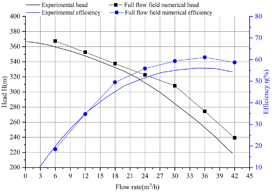
Comparison of numerical values of pump head (H) and efficiency (η) with test results.
Analysis of the flow characteristics of full flow field
Pressure field analysis of full flow field
The axial section pressure distribution of the full flow field in centrifugal pump under rated flow is shown in Figure 9. This figure conforms to the pressure distribution law of the multi-stage pump. The pressure range of the whole centrifugal pump is −38.1 kPa to 3.07 MPa. The fluid is pressurized by the impeller and guide vane of each stage. The pressure rises step by step and reaches the maximum at the outlet of the last stage guide vane. The impeller wear-ring clearance connects the inlet and outlet of the impeller, and there is a large pressure difference in the flow field in the clearance. The guide vane clearance connects the inlet and outlet of the guide vane, and the pressure difference of flow field in clearance is small.
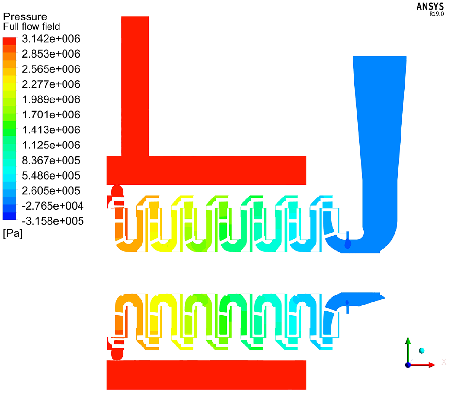
Axial section pressure distribution in the whole flow field of centrifugal pump.
Figure 10 shows the flow field pressure distribution in the axial section under rated flow of the first two stage impellers. It can be seen from the figure that after the fluid in the flow channel of impeller 1 is sucked in under negative pressure, the pressure increases continuously during the high-speed rotation, and the maximum value appears at the outlet of the impeller, which is about 0.267 MPa. After the diffuser action of the guide vane 1, the fluid pressure is increased. It can be seen that the fluid pressure at the inlet of the impeller 2 is significantly higher than that at the outlet of impeller 1, and the inlet pressure is 0.316 MPa. In this way, the fluid is pressurized in several stages and finally reaches a high pressure of 3 MPa at the outlet of centrifugal pump.

The flow field pressure distribution of impeller in axial section: (a) impeller 1 and (b) impeller 2.
Figure 11 shows the flow field pressure distribution in the radial section of the impeller 1 and the guide vane 1. The pressure in the impeller flow channel is distributed symmetrically in the center, and the pressure distribution is relatively uniform. Before the liquid thrown from the impeller enters the flow channel of the guide vane, part of the liquid is blocked by the volute tongue of the guide vane, and the flow velocity decreases, and there is a local high-pressure area there. Comparing 11(a) and 11(b), it can be seen that the existence of the wear-ring clearance will cause partial backflow of the liquid after being thrown from the impeller outlet, resulting in a decrease in the pressure in the diffuser section of the guide vane of the centrifugal pump, which can be seen in Figure 12.

Radial cross-sectional flow field pressure distribution of impeller 1 and guide vane 1: (a) full flow field (with wear-ring clearance), and (b) main flow field (without wear-ring clearance).

Axial cross-sectional streamline diagram of impeller 1 and guide vane 1 in the full flow field.
The pressure distribution of the axial section flow field in the wear-ring clearance of the impeller and guide vane is shown in Figure 13. The pressure range of the first-stage impeller wear-ring clearance is −38.1 kPa to 0.424 MPa, and the pressure range of the second-stage impeller wear-ring clearance is 0.295–0.742 MPa. The pressure range of the final stage impeller wear-ring clearance is 2.54–2.89 MPa, and the pressure difference between inlet and outlet is about 0.4 MPa. The pressure difference between the inlet and outlet of the guide vane wear-ring clearance is small, so volume loss is relatively small, while the pressure difference between the inlet and outlet of the impeller wear-ring clearance is large, which makes part of the high-pressure fluid thrown out from the impeller outlet flow back to the impeller inlet again, causing a certain volume loss and pressure loss, which also provides evidence for the pressure reduction in the diffuser section of the guide vane mentioned above.

The pressure distribution of the axial section flow field in wear-ring clearance: (a) the first stage wear-ring clearance, (b) secondary wear-ring clearance and (c) final stage wear-ring clearance.
Velocity field analysis of full flow field
Figure 14 shows the axial section velocity distribution of the full flow field for a centrifugal pump at the rated flow. The fluid has experienced multiple acceleration and deceleration processes in the flow channel of the centrifugal pump, and the velocity field between different stage of guide vanes is almost unchanged. When the fluid passes through the impeller, it rotates at a high speed to obtain a higher kinetic energy. The maximum speed appears at the outlet of the impeller. Then it passes through the guide vane assembly, and some kinetic energy is converted into static pressure energy through deceleration to achieve pressurization due to the increase of the flow area. It flows back to the next impeller through the middle section along the radial direction and continues the previous process until it flows out from the last stage guide vane to the cylinder. Finally, the fluid is pumped out from the outlet of the centrifugal pump under the action of high pressure. The fluid flow rate in the wear-ring clearance of impeller is about 5.72 m/s, which means that there is more backflow caused by the pressure difference, and the volume loss is large, while the fluid pressure difference in the wear-ring clearance of guide vane is smaller, so the flow rate here is very small.
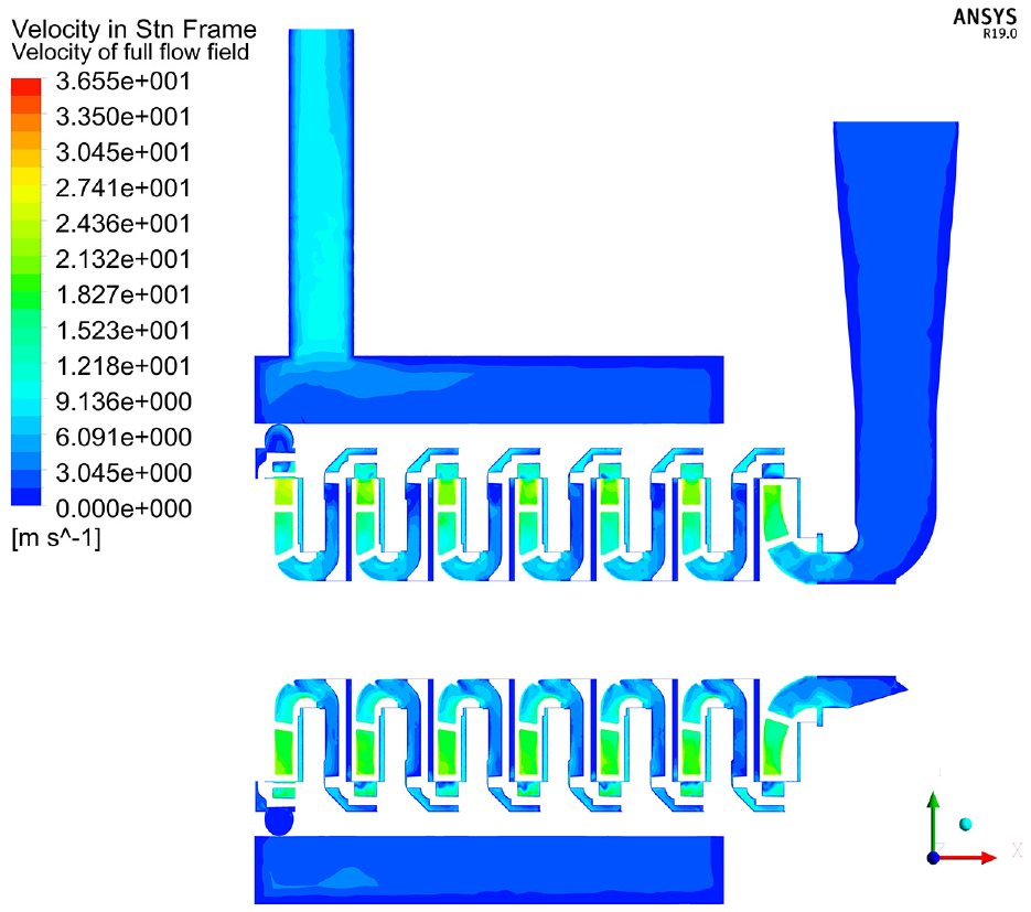
Axial section velocity distribution in the whole flow field of centrifugal pump.
The velocity distribution of the radial section of the centrifugal pump impeller 1 is shown in Figure 15. After the liquid enters the impeller, the speed gradually increases along the flow direction through the work done by the blades, and it is distributed symmetrically in the center. However, the velocity distribution at the inlet of the impeller is not uniform. Compared with Figure 16(a) and (b), it can be seen that the existence of the wear-ring clearance reduces the velocity at the impeller inlet of full flow field, and the velocity distribution is more uneven. This is because part of the liquid thrown out from the impeller flows back to the impeller inlet through the wear-ring clearance, interacts with the incoming flow from the inlet, and generates unstable structures such as vortex. After the fluid enters the impeller, it is impacted by the high-speed rotating blades, resulting in backflow, which makes the fluid flow more unstable, as can be seen in Figure 17. In addition, Figure 17 also shows that the flow velocity in the impeller wear-ring clearance is much larger than that in the guide vane wear-ring clearance, and the former has a greater effect on the impeller inlet velocity than the latter.

Radial velocity distribution of impeller 1: (a) full flow field (with wear-ring clearance) and (b) main flow field (without wear-ring clearance).

The inlet velocity distribution of impeller 1: (a) full flow field (with wear-ring clearance), and (b) main flow filed (without wear-ring clearance).

Axial section velocity distribution of impeller 1 wear-ring clearance in the full flow field: (a) velocity cloud diagram, and (b) velocity vector diagram.
As shown in Figure 18, the velocity distribution of the radial section of impeller 1 and guide vane 1 was further analyzed. The high-speed rotating liquid in the impeller is thrown out from the outlet and enters the diffuser section of the guide vane. The flow area increases, the speed decreases, and part of the kinetic energy is converted into static energy, which further increases the fluid pressure. In addition, by carefully observing the red box in Figure 18(a), it can be seen that when the outlet end of the impeller blade rotates to the vicinity of the volute tongue, the fluid velocity near the blade end and the volute tongue is significantly reduced due to the impelling effect of the blade and the reduction of the flow area, and backflow is generated, as shown in Figure 18(b). Therefore, there is a local high-pressure area, which is consistent with the previous pressure analysis.

The velocity distribution of the radial section of impeller 1 and guide vane 1: (a) velocity cloud diagram, and (b) velocity vector diagram.
Flow field analysis under different flow rates
The streamline diagram of the radial section of impeller 1 and guide vane 1 under the flow rate of 0.2–1.4 Qd is shown in Figure 19. When the flow is small, the rotating speed of the impeller blade is far greater than the fluid velocity, so there is obvious vortex on the suction surface of the blade and the pressure surface at the outlet. With the increase of flow, the vortex on the pressure surface of the blade at the outlet disappears first, the vortex size on one side of the suction surface gradually decreases, the number of vortices decreases, and the flow state in the impeller gradually improves. When Q = 1.0Qd, there is a phenomenon of vortex and flow separation in the impeller, causing a certain energy loss and reducing the efficiency of the pump.

Streamline diagram of impeller 1 and guide vane 1 at different flow rates: (a) Q = 0.2Qd, (b) Q = 0.4Qd, (c) Q = 0.6Qd, (d) Q = 0.8Qd, (e) Q = 1.0Qd, (f) Q = 1.2Qd, and (g) Q = 1.4Qd.
Analysis of entropy production in the full flow field
In order to simplify the setting of the Interface surface, the inlet section includes the impeller wear-ring clearance of impeller 1, the guide vane 1 includes the guide vane wear-ring clearance of the impeller 1 and the impeller wear-ring clearance of the impeller 2, the guide vane 2 includes the guide vane wear-ring clearance of the impeller 2 and the impeller wear-ring clearance of the impeller 3, the guide vanes 3–6 are derived in turn, and the last stage guide vane includes the guide vane wear-ring clearance of the impeller 7, excluding the impeller wear-ring clearance.
The distribution and proportion of entropy production of flow passage components in the full flow field of centrifugal pump under rated flow are shown in Figure 20. It can be seen from the figure that the guide vane has a much higher entropy production than that of the impeller. The entropy production of all guide vanes accounts for 78% of the total entropy production and is the main energy consumption part of the multi-stage centrifugal pump. In addition, the entropy production of the first six stage guide vanes includes the entropy production value of the guide vane itself, the impeller wear-ring clearance and the guide vane wear-ring clearance. Compared with other guide vanes, the last stage guide vane lacks the impeller wear-ring clearance, and its entropy production value is significantly smaller than that of other guide vanes, indicating that the impeller wear-ring clearance is also the main energy consuming part, which will be confirmed later.
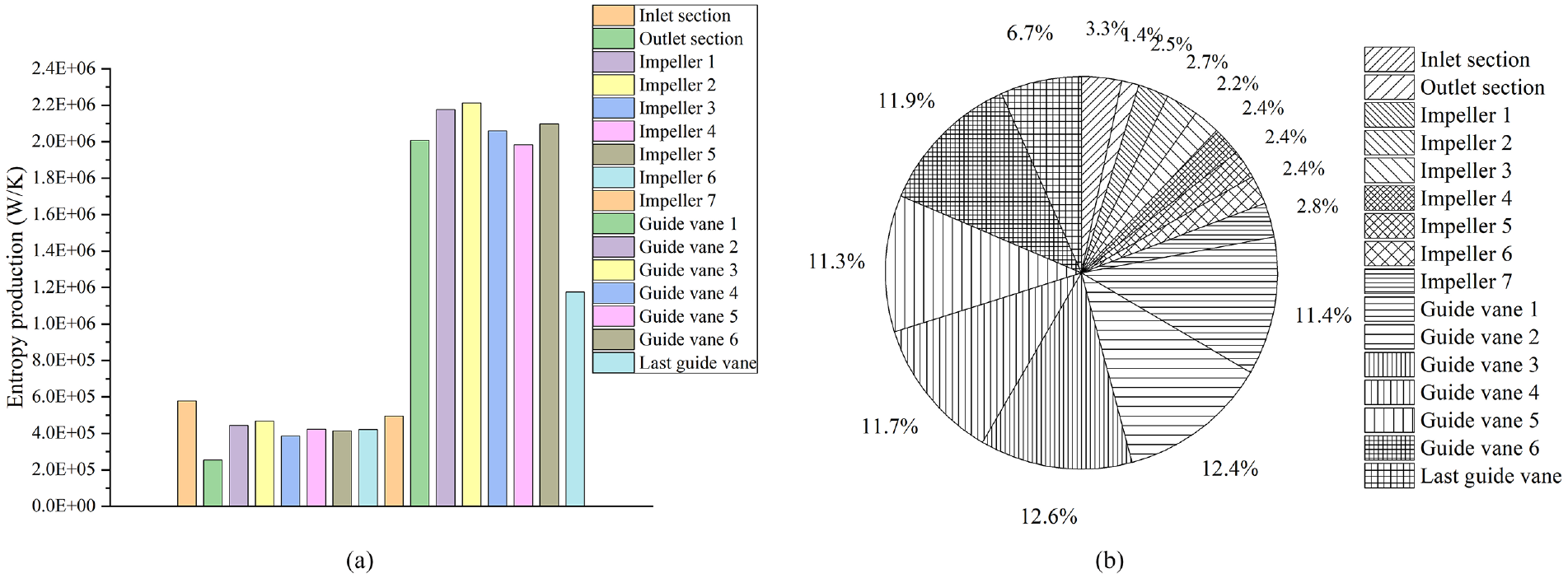
Entropy generation distribution and proportion of flow passage components in the whole flow field under rated flow: (a) histogram and (b) pie chart.
The entropy production under different flow conditions of typical flow passage components in the centrifugal pump (such as inlet section, impeller 1, guide vane 1, etc.) was analyzed, as shown in Figure 21. In Figure 21(a), the total entropy production of full flow field in centrifugal pump first decreases rapidly and then increases with the increase of flow. When Q = 36 m3/h, the entropy production value is the smallest, and the minimum value is 1.5 × 10⁷W/K. The entropy production in the outlet section has the smallest value among all flow passage components, and it shows an upward trend with the increase of flow rate, while the entropy production in the inlet section decreases with the increase of the flow rate. The trend of entropy production of impeller 1, impeller 2, guide vane 1 and last-stage guide vane with the flow rate is consistent with the total entropy production, which first decreased and the increased. Among them, the guide vane 1 has the highest entropic yield, followed by the last one, and the impeller 1 and 2 have the lowest. The difference of the entropic yield between the guide vane and the impeller increases with the increase of flow rate. When the liquid flows through the guide vane, the flow area increases, the flow velocity decreases, and part of the kinetic energy is converted into static pressure energy. This process produces unstable structures such as vortex, and the energy loss is large. And in the process of reversing the flow back to the impeller through the guide vanes, there is more turbulent dissipation. The main function of the impeller is to apply work on the fluid to increase its kinetic energy, and its energy loss is less than that of the guide vane. Comparing Figure 21(a) and (b), it can be seen that under the same flow conditions, the total entropy production value of full flow field is higher than that of main flow field. In addition, when the flow rate is low, the entropy production of the last stage guide vane in the main flow field is lower than that of the impeller, and the entropy production of the inlet section is lower than that of the inlet section in the full flow field, indicating that the existence of the wear-ring clearance increases the entropy production of the full flow field and increases the energy consumption of the centrifugal pump.

Comparison of entropy production of typical flow passage components in full flow field and main flow field under different flow rates: (a) full flow field (with wear-ring clearance), and (b) main flow field (without wear-ring clearance).
Figure 22 shows the entropy production distribution of axial section in the full flow field of centrifugal pump. It can be seen from the figure that the entropy production range and magnitude in the guide vane area are the highest, and the entropy production in the impeller wear-ring clearance area is also relatively high. Figure 23 shows the distribution of entropy production in the axial section of impeller 1 and impeller 2 in the full flow field. The distribution of entropy production of the two impellers is similar and uneven. The entropy production at the inlet, outlet and two side walls of the impeller is high. Further, the entropy production distribution of the wear-ring clearance under different flow rates was analyzed, as shown in Figure 24. It can be seen that the entropy production of the guide vane wear-ring clearance is much smaller than that of the impeller wear-ring clearance, indicating that the influence of the impeller wear-ring clearance on the increase of the entropy production in full flow field is greater than that of the guide vane wear-ring clearance. The flow velocity at the outlet of impeller wear-ring clearance is large, which is opposite to the inlet flow direction. The two interact to form vortex backflow, resulting in large energy loss. Therefore, the existence of impeller ring clearance increases the entropy production at the impeller inlet. In addition, as the flow increases, the high entropy production area at the impeller inlet first decreases and then increases. When Q = 36 m3/h, the entropy production is the minimum, and the pump efficiency is the highest.
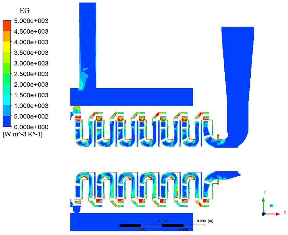
The entropy production distribution of axial section in centrifugal pump.

The entropy production distribution of axial section in impeller of full flow field: (a) impeller 1 and (b) impeller 2.
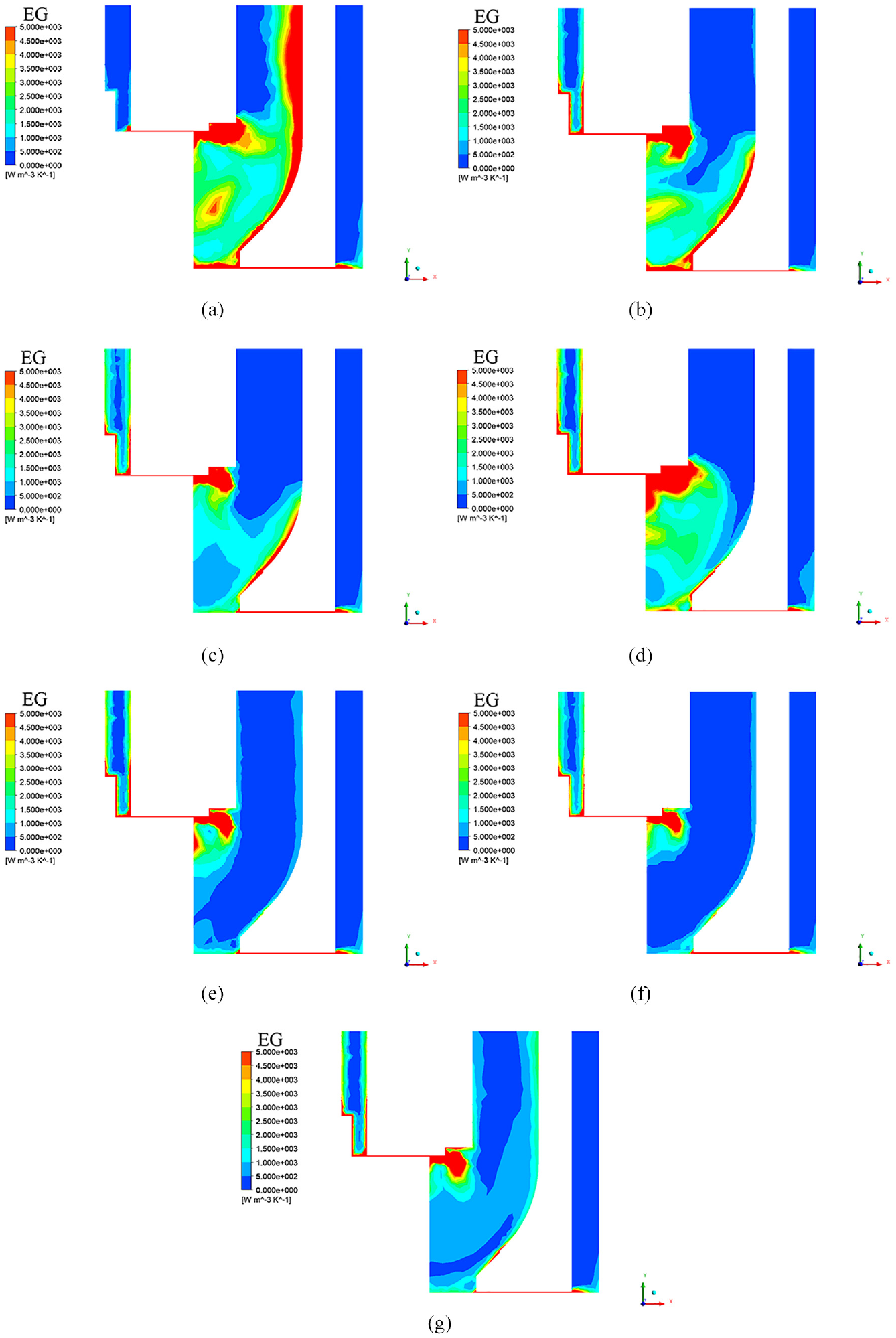
The distribution of entropy production in the wear-ring clearance under different flow rates: (a) Q = 6 m3/h, (b) Q = 12 m3/h, (c) Q = 18 m3/h, (d) Q = 24 m3/h, (e) Q = 30 m3/h, (f) Q = 36 m3/h, and (g) Q = 42 m3/h.
Conclusion
In this paper, the internal flow characteristics of full flow field considering clearance flow in a multi-stage centrifugal pump were analyzed numerically and verified by experiment. The entropy production theory was applied to compare the distribution law of full flow field with and without wear-ring clearance at rated flow, and the range and magnitude of the main energy loss in the pump were quantitatively analyzed. The main conclusions are as follows:
The wear-ring clearance makes the fluid flow back to the impeller inlet after being thrown out from the impeller outlet, resulting in pressure reduction in the diffuser section of guide vane of centrifugal pump. Among them, the influence of the impeller wear-ring clearance on the pressure reduction in the diffuser section is greater than that of the guide vane wear-ring clearance.
The velocity distribution of fluid in each stage impeller and guide vane flow channel is almost the same, the flow velocity in the impeller wear-ring clearance is greater than that of guide vane wear-ring clearance. The existence of the wear-ring clearance reduces the velocity at the impeller inlet of full flow field, and the velocity distribution is more uneven.
The guide vane has the highest entropy production value and proportion, which is the main energy consumption part in the centrifugal pump. The existence of the wear-ring clearance increases the total entropy production value and energy consumption of the centrifugal pump. The entropy production range and magnitude of the impeller wear-ring clearance are larger than that of the guide vane wear-ring clearance. With the increase of flow rate, the total entropy production of centrifugal pump first decreases and the increases.
Footnotes
Appendix
Handling Editor: Chenhui Liang
Declaration of conflicting interests
The author(s) declared no potential conflicts of interest with respect to the research, authorship, and/or publication of this article.
Funding
The author(s) disclosed receipt of the following financial support for the research, authorship, and/or publication of this article: This work is supported by NSFC (National Natural Science Foundation of China)-Shandong Joint Fund (U2006221), Shandong provincial fund (ZR2021ME161), Ocean industry leading talent team of Yantai’s “Double Hundred Plan,” the Key Research and Development Project of Shandong Province (2019GGX102058). We feel grateful for their kind support.