
Abstract
The manufacturing of optical free-form surface is a difficult point in industry, so the development and research of the integrated manufacturing equipment for optical free-form surface has become a key issue. In the paper, the flexible manufacturing cell for optical free-form surface with four Z-axis closed modules is developed, which includes 3D printing module, milling module, grinding module, and polishing module successively, the columns of the flexible manufacturing cell adopt a mechanical shunt design, the optical component is transferred from one module to another by the robot, positioned by the zero-point positioning system, and can be processed in each module in turn by coordinate transformation. The processed optical component has low surface roughness, low surface residual stress and surface damage, ensuring the optical component has good optical performance, the flexible manufacturing cell can achieve high-quality and high-efficiency machining of optical free-form surface. Because each module has similar structure, the milling module is carried out the static and dynamic simulation research using finite element (FE) method and virtual prototype (VP) method, the simulation results show that the milling module has excellent performances, the gravity balance device combined with the mechanical shunt column can significantly improve the precision of the milling module.
Keywords
Introduction
The free-form surface in optical system usually refers to the surface that cannot be expressed by spherical or aspherical coefficients. It also refers to any non-traditional, asymmetrical surface, or a surface that can only be expressed by parameter vectors. The free-form optical system is the next-generation optical system with excellent optical performance and advantages of system integration. The manufacturing of optical free-form surface which generally require nano-level machining precision is a comprehensive technology involving design,1–7 machining,8–19 and measurement.20,21
The most important aspect of the development of factory automation is through the use of flexible manufacturing systems (FMS). In flexible manufacturing system, each workpiece and each tool can be moved from one equipment to another by the corresponding workpiece and the tool automated guided vehicles, respectively. FMS can be defined as the general-purpose manufacturing machines, which are connected together by the material handling systems and can perform different types of operations, in these systems, the machines and material handling systems are controlled by a central computer system. 22
Nowadays, the development trend in FMS is toward the small edition of FMS, called flexible manufacturing cell (FMC). FMC may be deemed the most important achievement in low-volume manufacturing. 23 FMC is composed of multiple machine tools, equipped with equipments for automatic changing of workpieces and cutting tools, connected by material handling devices. 24 Flexible manufacturing cells have been used as the tool to improve the competitiveness of manufacturing systems. These highly automated manufacturing systems are becoming more and more important to the survival of modern industry, and attract more and more scholars to conduct researches solving many inherent problems in flexible manufacturing. 25 Different kinds of operation environments have been studied in Arzi and Iaroslavitz . 26 Generally, FMC runs under three different situations such as single batch production, flow production, and make-to-order production. In single batch production, the known sets of workpieces will be produced in a given time period. 27 However, in flow production, the workpieces are produced continuously in fixed and known proportions. During make-to-order situation, orders with different machining requirements are accepted randomly with different inter-arrival times and due dates. 28 Moreover, the authors Hutchison et al. 29 found that the routing flexibility can strengthens the system performance. Many key technologies are involved in the development of flexible manufacturing systems.30–36
The existing manufacturing equipments for optical free-form surface have single function and can only carry out discrete manufacturing, therefore, factory needs more equipments which occupy a larger workshop area and also increase the production cost at the same time, in addition, secondary clamping is needed when a variety of processing technologies are required, which leads to the reduction of machining precision and efficiency of optical free-form surface, furthermore, most of the existing machine tools are cantilever structure, which has the disadvantages of insufficient rigidity and low Z-axis precision caused by the gravity of the suspended part of machine tool.2,9,10 Aiming at the problems existing in the manufacturing process of optical free-form surface, the flexible manufacturing cell for optical free-form surface is developed based on ergonomics and esthetic theory, which can achieve the hybrid additive-subtractive manufacturing of optical free-form surface. The gravity of the upper part of each module flows out partly from Z-axis column without affecting the precision of the Z-axis, the symmetrical design of each module structure can reduce the influence of heat on manufacturing precision, 37 the mechanical condition of moving parts of each module is good, and each module can enhance the manufacturing precision when the gravity balance device is used. The research on the milling module can provide a theoretical reference for the scheme selection of the other modules.
Development of the flexible manufacturing cell for optical free-form surface
Process design of the flexible manufacturing cell for optical free-form surface
Operation steps of the flexible manufacturing cell for optical free-form surface:
Step 1: The system boots, the manufacturing cell controller regulates the gravity balance device of the 3D printing module to start to ensure the precision of the 3D printing module, then the optical component model input to the manufacturing cell controller is printed, at the same time, the molten pool condition is detected online, if the test is not qualified, the process parameters are changed to continue printing. After printing, the quality of the optical component is detected online, if the test is not qualified, we change the process parameters to continue printing until the test is qualified;
Step 2: The manufacturing cell controller regulates the milling cutter replacement robot to carry the fixture and the optical component from the 3D printing module to the milling module, and regulates the gravity balance device of the milling module to start to ensure the precision of the milling module, for the worn milling cutter, the milling cutter is replaced using the milling cutter replacement robot and the milling cutter library. After each stage of the rough milling, the semi-finish milling and the finish milling is finished, the quality of the optical component is detected online, if the test is not qualified, we change the process parameters to continue processing until the test is qualified;
Step 3: The manufacturing cell controller regulates the grinding wheel replacement robot to carry the fixture and the optical component from the milling module to the grinding module, and regulates the gravity balance device of the grinding module to start to ensure the precision of the grinding module, for the worn grinding wheel, the grinding wheel is trimmed using the grinding wheel replacement robot and the grinding wheel dresser, the grinding wheel is replaced using the grinding wheel replacement robot and the grinding wheel library. After each stage of the rough grinding, the semi-finish grinding and the finish grinding is finished, the quality of the optical component is detected online, if the test is not qualified, we change the process parameters to continue processing until the test is qualified;
Step 4: The manufacturing cell controller regulates the polishing pad replacement robot to carry the fixture and the optical component from the grinding module to the polishing module, regulates the gravity balance device of the polishing module to start to ensure the precision of the polishing module, and calculates the position of the ultrasonic spray robot according to the relative position of the optical component and the polishing pad during the polishing process, for the worn polishing pad, the polishing pad is trimmed using the polishing pad replacement robot and the polishing pad dresser, the polishing pad is replaced using the polishing pad replacement robot and the polishing pad library. After each stage of the fast polishing and the fine polishing is finished, the quality of the optical component is detected online, if the test is not qualified, we change the process parameters to continue processing until the test is qualified.
Figure 1 is the process design of the flexible manufacturing cell for optical free-form surface, including the stage of 3D printing, the processing stage of milling, the processing stage of grinding, and the processing stage of polishing, the optical component is transferred from one module to another by the robot, positioned by the zero-point positioning system, and can be processed in each module in turn by coordinate transformation.

Process design of the flexible manufacturing cell for optical free-form surface.
Structure design of the flexible manufacturing cell for optical free-form surface
Figure 2 is the structure topology graph of each module of the flexible manufacturing cell for optical free-form surface, the structure topology graph could describe the motion transmission relationship of each module of the flexible manufacturing cell for optical free-form surface.
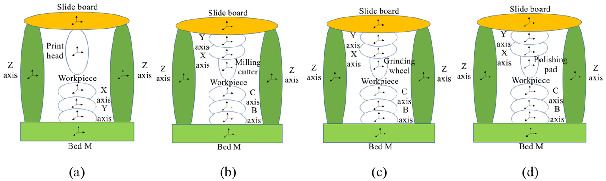
Structure topology graph of each module of the flexible manufacturing cell for optical free-form surface: (a) 3D printing module, (b) Milling module, (c) grinding module, and (d) polishing module.
Figure 3 is the three-dimensional man-machine engineering drawing of the flexible manufacturing cell for optical free-form surface. The protective door of each module adopts styling design, the height ratio of the protective door of each module to the flexible manufacturing cell for optical free-form surface is the golden ratio.
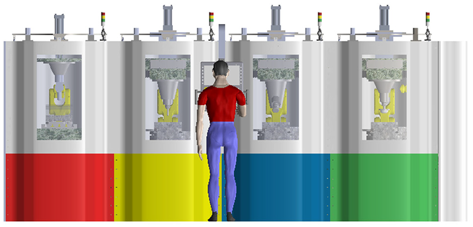
3D man-machine engineering drawing of the flexible manufacturing cell for optical free-form surface.
The main body size of the flexible manufacturing cell for optical free-form surface is 1400 mm × 2000 mm × 5000 mm, the X-axis, the Y-axis, and the Z-axis travel of each module are 400, 400, and 280 mm, respectively. the columns of the flexible manufacturing cell adopt a mechanical shunt design, each module is equipped with a gravity balance device, the workbenches and the robots are accurately positioned to ensure the realization of coordinate transformation, and each module adopts different precision designs and stiffness designs according to process characteristics. The front lower side protection of the 3D printing module can be painted red, the front lower side protection of the milling module can be painted yellow, the front lower side protection of the grinding module can be painted blue, the front lower side protection of the polishing module can be painted green, and the rest are painted white. Figure 4(a) and (b) is the two-dimensional view of the flexible manufacturing cell for optical free-form surface without internal and external protection.
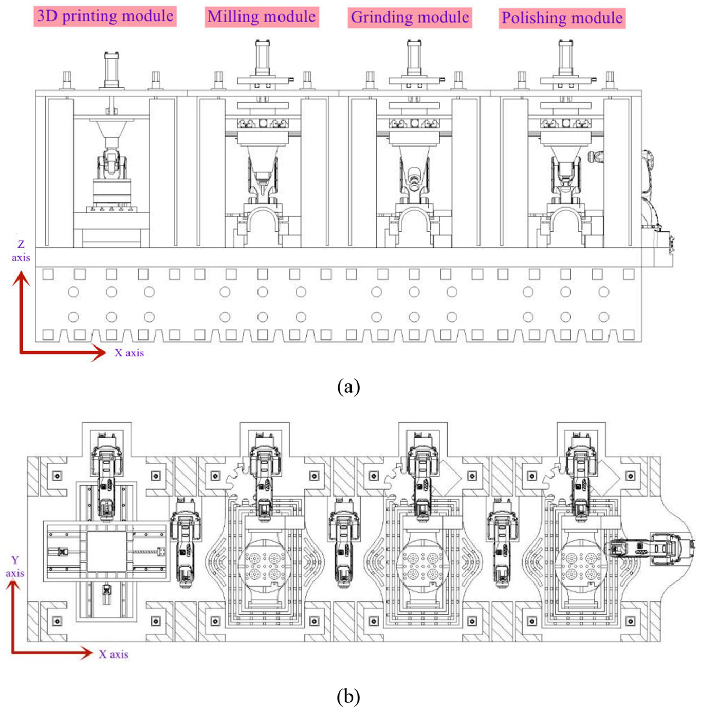
2D view of the flexible manufacturing cell for optical free-form surface: (a) front view and (b) internal view.
Research on the performances of the milling module
Study on the static performances of the milling module
Features of the milling module
Gravity transfer path refers to the force flow path of the suspended gravity in the milling module, the lifting force of the gravity balance device is the sum of the gravity of the slide board

Gravity transfer path of the milling module: (a) roof + gravity balance not working, (b) roof + gravity balance working, (c) column + gravity balance not working, and (d) column + gravity balance working.
Figure 6(a) is the working principle of the fixed gravity balance device. The fixed gravity balance device is composed of an oil cylinder and its connecting components, the fixed gravity balance device can balance the gravity of the suspended part of the milling module, however, due to the movement of the X-axis and Y-axis of the milling module, the gravity center of the suspended part of milling module changes continuously, and the gravity moment generated will affect the milling module precision. And Figure 6(b) is the working principle of the two-dimensional motion gravity balance device. The two-dimensional motion gravity balance device is composed of an oil cylinder and its connecting components, a two-dimensional main motion platform and a two-dimensional follow-up motion platform, when working, the two-dimensional main motion platform moves according to the position of the calculated gravity center, ensuring the gravity center of the suspended part of the milling module is always on the axis of the oil cylinder, when the milling module moves from the origin position (0, 0) to the coordinate (

Working principle of the gravity balance device: (a) the fixed gravity balance device and (b) the two-dimensional motion gravity balance device.
The establishment of the finite element model
The establishment of the finite element model is divided into three stages. Firstly, the simplified three-dimensional geometric model of the milling module is established according to the requirements of the drawings. Then we conduct material property definition, mesh division, and contact element generation (Considering the stiffness and damping characteristics of the joint surface) to generate an equivalent finite element model. Finally, according to the working state and force situation of the milling module, the boundary constraint conditions and the force loads are loaded to generate a mechanical model.
This paper uses three-dimensional modeling software to establish a three-dimensional model of the whole milling module. The basic parts of the milling module, bed, column, etc. are all large parts, including a large number of rounded corners, bolt holes, smaller bosses, etc. If building a 3D model, we model these solid features one by one, it is bound to increase the amount of the finite element calculation and the difficulty of meshing, and these detailed features have negligible influence on the results of the finite element analysis. Therefore, it is necessary to make the simplifications when building the three-dimensional model. The simplified contents are as follows: we omit the X, Y-axis servo motors and other functional parts that do not perform quantitative analysis.
We use ABAQUS finite element software to carry out the statics modeling and analysis on the milling module, where the Z-axis motor is installed on the roof or column, the main structure material of the milling module is cast iron or natural granite. The elastic modulus of the cast iron is 120 GPa, the Poisson’s ratio is 0.25, and the density is 7300 kg/m3. The elastic modulus of the natural granite is 55 GPa, the Poisson’s ratio is 0.3, and the density is 2800 kg/m3. Load loading situation: when the milling module is only subjected to the gravity, the gravity load is applied to the entire model, and the load direction is downward along the Z-axis, when the milling module is under the combined action of the gravity load and the cutting load, in addition to the gravity load, the cutting load Fx = 100 N, Fy = 100 N, Fz = 100 N is applied at the same time, according to whether the gravity balance device is working or not, the balance force is applied or not, and the value of the balance force is the gravity of the balanced part. Figure 7 shows the finite element model of the milling module, where the Z-axis motor is installed on the roof.

Finite element model of the milling module (the Z-axis motor is installed on the roof).
Simulation results and analysis of the milling module under gravity load
The static deformation represents the static stiffness characteristics of the structure, when the gravity balance device is not working (equivalent to the non-shunt design), the milling module (Roof + Cast iron) is under gravity load, the space error is shown in Figure 8(a), the maximum space error of the milling module is 28 μm, and the maximum space error is located at the spindle of the milling module. When the gravity balance device is working, the milling module is under gravity load, the space error is shown in Figure 8(b), the maximum space error of the milling module is 46 μm, and the maximum space error is located at the roof of the milling module.

Space error of the milling module (Roof + Cast iron): (a) gravity balance not working and (b) gravity balance working.
At the origin position of the milling module, the straightness of the Z-axis guide rail is 0.8 μm when the gravity balance device is not working, and the straightness of the Z-axis guide rail is 0.5 μm when the gravity balance device is working, the straightness of the Z-axis lead screw is 5 μm when the gravity balance device is not working, and the straightness of the Z-axis lead screw is 8 μm when the gravity balance device is working. Figure 9(a) to (c) shows the space error of the milling module spindle end, respectively, when the gravity balance is not working, the fixed gravity balance is working, and the two-dimensional motion gravity balance is working, Z = 0, X-axis and Y-axis are in different working positions. It can be seen that the maximum space error of the spindle end is 28 μm when the gravity balance device is not working, the maximum space error of the spindle end is 7.3 μm when the fixed gravity balance device is working, and the maximum space error of the spindle end is 5.8 μm when the two-dimensional motion gravity balance device is working. Due to the structural symmetry, the space errors are distributed symmetrically along the X-axis and Y-axis.

Space error of the spindle end in different working positions (Roof + Cast iron) (gravity load): (a) the gravity balance is not working, (b) the fixed gravity balance is working, and (c) the two-dimensional motion gravity balance is working.
The difference between the maximum space error and the minimum space error is 3.5, 2.7, and 1.4 μm, respectively, which will affect the repeat positioning precision during non-machining. It can be seen that the fixed gravity balance can significantly reduce the difference of the maximum space error and the minimum space error of the spindle end, and the two-dimensional motion gravity balance can further reduce this difference.
Table 1 shows the space error of the spindle end of adopting different schemes under gravity load, when different types of gravity balance device are used.
The space error of the spindle end under gravity load.

Table 2 shows the straightness of the Z-axis guide rail and the Z-axis lead screw of adopting different schemes. It can be seen that the straightness error of the Z-axis guide rail and the Z-axis lead screw can be reduced when the gravity balance is working, but when the Z-axis motor is installed on the roof, the straightness error of the Z-axis lead screw increases. Figure 10(a) shows the straightness of the Z-axis guide rail and the Z-axis lead screw of adopting different structural schemes, when the cast iron is used for the structural material, the gravity balance device is working or not. Because there is no mechanical backflow effect, when the gravity balance device is working, the Z-axis motor installed on the column compared with roof can greatly reduce the straightness error of the guide rail and the lead screw. Figure 10(b) shows the straightness of the Z-axis guide rail and the Z-axis lead screw of adopting different structural schemes, when the natural granite is used for the structural material, the gravity balance device is working or not. It can be seen that the use of the natural granite as the structural material can significantly reduce the straightness error of the guide rail and the lead screw, under the same working conditions compared with the cast iron. The optimal design scheme of static characteristic is that the Z-axis motor of the milling module is installed on the column and the structural material is natural granite.
The straightness of the Z-axis guide rail and the Z-axis lead screw.


The straightness of the Z-axis guide rail and the Z-axis lead screw: (a) cast iron and (b) natural granite (1.0-scheme: roof + gravity balance not working; 2.0-scheme: roof + gravity balance working; 3.0-scheme: column + gravity balance not working; 4.0-scheme: column + gravity balance working).
When the Z-axis motor of the milling module is installed on the column, the structural material is natural granite. Figure 11(a) is the space error of the Z-axis guide rail, respectively, when the gravity balance is not working, the fixed gravity balance is working, and the two-dimensional motion gravity balance is working, Z = 0, the X-axis and Y-axis travel is largest. Figure 11(b) is the space error of the Z-axis lead screw, respectively, when the gravity balance is not working, the fixed gravity balance is working, and the two-dimensional motion gravity balance is working, Z = 0, the X-axis and Y-axis travel is largest. It can be known that the gravity balance device can greatly reduce the straightness error of the Z-axis guide rail and the Z-axis lead screw, the two-dimensional motion gravity balance device compared with the fixed gravity balance device can further reduce the straightness error of the Z-axis guide rail and the Z-axis lead screw.

Space error of the Z-axis guide rail and the Z-axis lead screw: (a) guide rail and (b) lead screw.
Simulation results and analysis of the milling module under gravity load and cutting load
Figure 12(a) to (c) shows the space error of the milling module (Roof + Cast iron) spindle end, respectively, when the gravity balance device is not working, the fixed gravity balance device is working, and the two-dimensional motion gravity balance device is working, under gravity load and cutting load, Z = 0, X-axis and Y-axis are in different working positions. It can be seen that the maximum space error of the spindle end is 29 μm when the gravity balance device is not working, the maximum space error of the spindle end is 8 μm when the fixed gravity balance device is working, and the maximum space error of the spindle end is 6.3 μm when the two-dimensional motion gravity balance device is working. At the origin position, the stiffness in three directions of the spindle end is Kx = 95 N/μm, Ky = 56 N/μm, and Kz = 34N/μm. The space errors are distributed approximately symmetrically along the X-axis and Y-axis, but the degree of symmetry is reduced due to the cutting load.

Space error of the spindle end in different working positions (roof + cast iron) (gravity load + cutting load): (a) the gravity balance is not working, (b) the fixed gravity balance is working, and (c) the two-dimensional motion gravity balance is working.
The difference between the maximum space error and the minimum space error is 3.5, 3.7, and 2 μm, respectively, which will affect the repeat positioning precision during machining. Table 3 shows the space error and the stiffness of the spindle end in three directions of adopting different schemes under gravity load and cutting load, when different types of gravity balance device are used.
The space error and the stiffness of the spindle end under gravity load and cutting load.

It can be seen that the fixed gravity balance has no significant influence on the difference of the maximum space error and the minimum space error of the spindle end under gravity load and cutting load, and the two-dimensional motion gravity balance can significantly reduce the difference under gravity load and cutting load. Figure 13 shows the stiffness of the spindle end of adopting different structural schemes and material schemes. It can be seen that the Z-axis motor installed on the roof compared with column can slightly increase the stiffness of the spindle end. The structure material using the natural granite compared with the cast iron can significantly increase the stiffness of the spindle end. The stiffness in X-axis direction is greater than in Y-axis direction, the stiffness in Y-axis direction is greater than in Z-axis direction. According to the simulation results of the structure statics, the static deformation laws are summarized, and the structure optimization design is guided.

The stiffness of the spindle end of adopting different schemes.
Study on the dynamic performances of the milling module
Virtual prototype of the milling module
ADAMS is a kind of virtual prototype analysis software. The whole milling module is modeled by SolidWorks, and it is introduced into the ADAMS/View module to establish a virtual prototype of the milling module, where the Z-axis motor is installed on the roof. The Z-axis characteristics of the milling module are simulated and analyzed. In ADAMS, firstly we set up the working environment including gravity options and unit options. Secondly we add the component constraints of the model including parameter information such as stiffness and damping. Thirdly we define the materials of the milling module components, the main structure material of the milling module is cast iron. Fourthly we create the rotation speed of the Z-axis motor. Fifthly we apply the balance force according to whether the gravity balance device is working or not. Sixthly the milling module needs to be softened. Finally we check whether there are incompletely defined components and over-constraints in the model. After the system model is successfully verified, the Z-axis characteristics of the milling module can be dynamically simulated. Simulation results can be obtained in ADAMS/PostProcessor module.
Virtual simulation of the milling module
Since the milling module spindle, the X-axis motion mechanism, and the Y-axis motion mechanism are installed on the slide board, when the Z-axis motor drives the slide board, the spindle also moves at the same time. When the Z-axis motor rotates at a constant rotation speed (300 rpm). Figure 14(a) shows the X-direction projection curve of the Z-axis screw nut, the curve is full period fluctuation function regularly, the first fluctuation range is between 0° and −120°, the second fluctuation range is between −40° and −105°, each fluctuation cycle is very short. Figure 14(b) shows the Y-direction projection curve of the Z-axis screw nut, the curve is full period fluctuation function regularly, the first fluctuation range is between 32° and −32°, the second fluctuation range is between 18° and −18°, each fluctuation cycle is very short. Figure 14(c) shows the Z-direction projection curve of the Z-axis screw nut, the curve type is full period fluctuation function regularly, the first fluctuation range is between 160° and −160°, the second fluctuation range is between 125° and −125°, each fluctuation cycle is very short. The projection curve indirectly indicates the dynamic characteristics of the Z-axis screw.

Three-dimensional projection curve of the Z-axis screw nut: (a) X-direction, (b) Y-direction, and (c) Z-direction.
Figure 15(a) shows the torque curve of the Z-axis motor of using flexible multibody model when the gravity balance device is not working, the curve is full period fluctuation function regularly, each fluctuation cycle is very short, the maximum torque is about 2.45 N/m, the minimum torque is about 1.85 N/m, and the average torque is about 2.15 N/m. Figure 15(b) shows the torque curve of the Z-axis motor of using flexible multibody model when the gravity balance device is working, the curve is full period fluctuation function regularly, the fluctuation cycle when the gravity balance is working is smaller than when the gravity balance is not working, the maximum torque is about 0.24 N/m, the minimum torque is close to 0 N/m, the second minimum torque is about 0.075 N/m, and the average torque is about 0.15 N/m. The average torque is reduced by 93% when the gravity balance device is working.
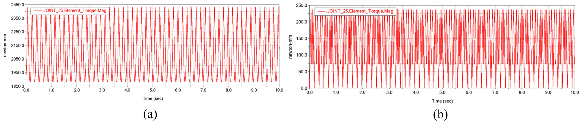
Torque curve of the Z-axis motor: (a) gravity balance not working and (b) gravity balance working.
Figure 16(a) shows the load curve of the Z-axis end bearing of using flexible multibody model when the gravity balance device is not working, the curve is full period fluctuation function regularly, each fluctuation cycle is very short, the maximum force is about 13,500 N, the minimum force is about 11,000 N, and the average force is about 12,500 N. Figure 16(b) shows the load curve of the Z-axis end bearing of using flexible multibody model when the gravity balance device is working, the curve is full period fluctuation function regularly, the fluctuation cycle when the gravity balance is working is smaller than when the gravity balance is not working, the maximum force is about 1300 N, the minimum force is close to 0 N, the second minimum force is about 400 N, and the average force is about 850 N. The average force is reduced by 93% when the gravity balance device is working.
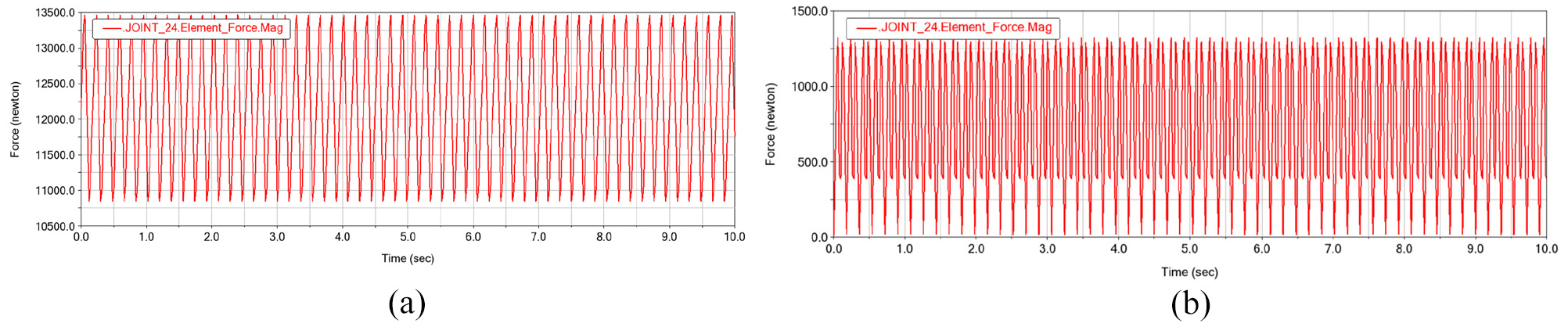
Bearing load curve of the Z-axis end: (a) gravity balance not working and (b) gravity balance working.
Conclusions
In this paper, aiming at the discrete manufacturing problems of optical free-form surface in the industry, the manufacturing strategy of achieving the hybrid additive-subtractive manufacturing of optical free-form surface is proposed, the flexible manufacturing cell for optical free-form surface is developed based on ergonomics and esthetic theory (Patent No.: ZL 2020 1 0008995. 1). It includes 3D printing module, milling module, grinding module, and polishing module in turn, each module adopts different precision designs and stiffness designs according to process characteristics, and the structure of each module can reduce the influence of gravity and heat on the machine tool precision compared to traditional machine tools. The following major conclusions are drawn:
The functional characteristics of the flexible manufacturing cell are clarified, the technological process of the flexible manufacturing cell is designed, and the structure design of the flexible manufacturing cell is carried out. The columns of the flexible manufacturing cell adopt a mechanical shunt design, the gravity on the upper part of the flexible manufacturing cell is partially transmitted from the columns, which does not affect the Z-axis precision of each module, and can also reduce the impact of heat and vibration generated by each module on adjacent modules. The flexible manufacturing cell can solve the discrete manufacturing problems in the industrial production process of optical free-form surface, the influence of the gravity balance device on the precision of the machine tool and the Z-axis dynamics is studied from a quantitative and qualitative perspective. Dynamic design combined with static design has become an trend in the development of machine tool, the use of finite element (FE) method and virtual prototype (VP) method in the design stage of machine tool can obtain more accurate static and dynamic characteristics information than traditional design methods.
The milling module of different structural schemes and material schemes are carried out the static analysis based on FEM. The simulation results show: The installation of the Z-axis motor on the roof can slightly increase the stiffness of the milling module, the installation of the Z-axis motor on the column can significantly increase the Z-axis guidance precision, the Z-axis driving precision, and the end precision of the milling module. Compared with the cast iron, the natural granite can greatly improve the stiffness, the Z-axis guidance precision, the Z-axis driving precision, and the end precision of the milling module. The optimal static characteristic design scheme is that the Z-axis motor is installed on the column and the structural material is natural granite, in the entire working space, the difference between the maximum space error and the minimum space error of the spindle end is 4.3 μm when the gravity balance device is not working, the difference between the maximum space error and the minimum space error of the spindle end is 3.2 μm when the fixed gravity balance device is working, and the difference is reduced by 26%, the difference between the maximum space error and the minimum space error of the spindle end is 1.5 μm when the two-dimensional motion gravity balance device is working, and the difference is reduced by 65%, therefore, the fixed gravity balance device can improve the machining precision, and the two-dimensional motion balance device can further improve the machining precision. According to the simulation results of the structure statics, the static deformation laws are summarized, and the structure optimization design is guided. The gravity balance device reduces the influence of gravity on the precision of the motion axis by changing the transmission path of gravity, the use of the gravity balance device combined with mechanical shunt column for gravity deformation compensation can significantly improve the precision of the milling module.
The milling module is carried out the dynamic analysis based on the flexible multibody dynamics. The simulation results show: The Z-axis load can be reduced effectively when the gravity balance device is working. When the gravity balance device is not working, the average torque of the Z-axis motor is 2.15 N/m, when the gravity balance device is working, the average torque of the Z-axis motor is 0.15 N/m, and the average torque is reduced by 93%. When the gravity balance device is not working, the average force of the Z-axis end bearing is 12,500 N, when the gravity balance device is working, the average force of the Z-axis end bearing is 850 N, and the average force is reduced by 93%, so the Z-axis motor load can be significantly reduced by unloading the Z-axis through the gravity balancing device, the gravity balance device can obviously improve the efficiency of the milling module. The obtained dynamic characteristics information of the milling module could provides data for the design of Z-axis components and control system.
Soon we will develop a physical prototype of the manufacturing cell, perform performance verification, and evaluate manufacturing capabilities.
Footnotes
Acknowledgements
This study was partially supported by the National Natural Science Foundation of China (Grant Nos. 2017YFA0701201).
Handling Editor: Chenhui Liang
Declaration of conflicting interests
The author(s) declared no potential conflicts of interest with respect to the research, authorship, and/or publication of this article.
Funding
The author(s) disclosed receipt of the following financial support for the research, authorship, and/or publication of this article: The work presented herein was conducted with the financial support of National Natural Science Foundation of China (Grant Nos. 2017YFA0701201).