
Abstract
A novel positioning error compensation method (PECM) based on the measured and target position error for multiple degrees of freedom (DOF) robot arm control is proposed, which is used to improve positioning accuracy of multiple-DOF robot arm end-effector in accurate positioning applications such as in the medical and mechanical fields. Based on the idea of PID to increase adaptiveness and robustness of the method, a positioning compensation model between the measured and target position error tracked by an optical tracking system and compensated joint angle is derived with inverse kinematic model. Based on error analysis of the compensation model regarding geometry errors, the proportional joint angle compensated coefficient deduced from Jaccobian matrix of the error is proposed and identified with position error data. Calibration experiments for position conversion matrix and positioning accuracy verification experiments are conducted consisting of an optical tracking system and a robot arm. The results of positioning accuracy verification experiments show that the average resultant positioning error in three directions reduces from 1.89 mm (before compensation, model based on Denavit-Hartenberg (DH)), 0.39 mm (model based on modified Denavit-Hartenberg (MDH) with Levenberg-Marquardt (LM)) to 0.34 mm (decreasing 82%, 15%), which demonstrates the efficiency and robustness of the method.
Introduction
Covid-19 promotes the development of industrial products that can be operated from distance and that are automated. As an indispensable part of automation, stemming from an urgent need to increase productivity, rapid development of robot arm can free people from dangerous or repetitive labor work, 1 promoting the trend of industrial internet. The extent of application of robot arm is an important indication of national industrial automation levels. 2
Robot arm is normally designed for repetitive work such as manufacturing and assembling (i.e. picking and placing, 3 welding, 4 drilling, 5 and so on) and medical procedures (i.e. laparoscopic surgery, 6 orthopedic surgery, 7 teeth implanting, 8 and so on). Taking dental implanting surgery as an example, to achieve higher reliability and extend service life of dental implants, the positioning error of dental implants through implant guide plate should be generally less than 2 mm to meet relatively high positioning accuracy of robot arm end-effector and realize a reliable medical treatment. 9 Therefore, quality implants require high positioning accuracy of the end-effector.
Though Robot arm has a high pose repeatability of ±0.02 mm, because the factors of mechanical errors in manufacturing, assembling and wearing procedure and control algorithm quality based on multiple sensors 10 can affect positioning accuracy, the absolute pose accuracy is relatively low, 11 which remains a challenging issue. Based on the analysis of the above factors, improving mechanical accuracy and modeling quality can increase positioning accuracy effectively. Improving mechanical accuracy is a method of increasing mechanical transmission efficiency by optimizing parts’ geometry parameters like structure dimension, rigidity and center of mass, 12 or utilizing high performance electronic components and new materials. 13 Improving mechanical accuracy requires changing inherent characteristics of mechanical systems, which increases costs and takes time. Moreover, due to relatively high mechanical accuracy of present mechanical parts, it is very hard to significantly reduce positioning error by improving mechanical accuracy, thus, improving modeling quality has become a more popular method among researchers.
Improving modeling quality is a method to build precise models based on system parameters or mechanical errors deduced and identified by theoretical analysis, measurement and calibration. This method is widely used because of low costs and reliable results. Improving modeling quality can be categorized into two types, namely, the method based on model parameters and that based on model-free parameters.14,15
The method based on model parameters needs to build a forward kinematics model and improve robot positioning accuracy through calibration, measurement and compensation rather than changing mechanical structure or design of the robot itself. 16 There are many models characterizing robot kinematics, such as DH (Denavit-Hartenberg) model, MDH (Modified Denavit-Hartenberg) model, CPC (Complete and Parametrically Continuous) model, S (Stone) model, etc., among which the most widely used model is DH model. 17 The parameters of DH model can be obtained by measurement, linear and nonlinear identification. With the use of a calibration algorithm based on the product-of-exponential formula, Mustafa et al. 18 improves the accuracy of the ABB industrial manipulator to 0.3 mm measured by a laser tracker system from Leica (AT901-MR). Zhang 19 establishes a homogeneous transformation error model among many robot systems based on DH and MDH kinematics models, and obtains compensation amount after SVD (Singular Value Decomposition). After compensation, the average distance error is reduced from 1.77 to 0.70 mm, and the absolute accuracy of robot arm positioning improves by at least 50%. To improve the position accuracy of the robot, Chen et al. 14 proposes a compensation method based on error similarity and error correlation. The positional error similarity in joint space based on the DH kinematic model of the robot and error correlation are presented to illustrate that Co-Kriging can be used to estimate the positional error of the robot for compensation. The experimental results show that the maximum absolute positional error is reduced to 0.29 mm with the compensation method. To identify robot geometric parameters of the DH kinematic model, Nguyen et al. 20 develops a calibration method with the EKF (Extended Kalman filter). The non-geometric errors are estimated using an ANN (Artificial Neural Network) for error compensation.
The method based on model-free parameter does not require establishing forward kinematics models, and there is no need to analyze the cause of the error. Instead, all the errors are regarded as joint angle error or positional error, and a mathematical method like training is used to approximate the data, and then improve the robot’s pose accuracy by modifying the joint angle. Shamma and Whitney 21 selects a polynomial as an approximate function of the joint correction value, fits the collected data with the least square method according to the discrete position error in the entire area of work space, and uses PUMA to carry out the calibration experiment with an average position error of 0.72 mm. Zhong et al. 22 applies ANN to take the measured pose and the corresponding joint angle errors as the input and output layer of the training network, and realizes joint error compensation in the local workspace. The training network can be used for online calibration. To compensate absolute errors for aerospace drilling robots, Yuan et al. 23 proposes a positioning error compensation method based on the extreme learning machine model. Considering the influence of geometric factors and the non-geometric factors of the robot, a positional error prediction model is built based on extreme learning machine, and the positional errors of prediction points can be predicted for compensation. The results also show that the average accuracy of robot tool center point is improved by 80.93%.
The main idea of the above papers is to improve the modeling accuracy between joint angles (or the errors) and poses (or the errors) of the robot arm end-effector through calibration or positioning methods including error modeling, pose measuring, parameter identification or compensation where the environment is well structured. 24 The above methods are complicated for robot controller making the calibration process less efficient, 25 and mainly concentrating on the accuracy of joint angles. Since joint angles have transformation relationship with the positions, the above methods don’t directly focus on position error. It means the accuracy highly depends on the relationship and will decrease with the accuracy of relationship decreasing caused by system changing such as mechanical wearing. To increase robustness and adaptiveness of the position method, our method originate from the idea of robotic control method – PID (Proportion Integral Differential). PID is a control scheme focusing on feedback output error in close loop, which can show high convergence without an accurate model of the physical system and prove high robustness.26,27 Likewise, our positioning method focuses on position error (feedback output error) and builds up the corresponding model to make the error decrease, namely, the position error is compensated according to the real-time measured positions of the robot arm in the experiment, so it will control positions directly and effectively promote the positioning accuracy. With the help of the optical tracking system with higher positioning resolution (0.05–0.3 mm) and faster response speed (>60 Hz), the position error is measured and calculated in real time which is used for positioning compensation, so as to reduce position error directly.
In this paper, a positioning error compensation method based on position errors for robot arm control is proposed to improve positioning accuracy of the robot arm end-effector. The remainder of this paper is organized as follows. Section 2 introduces the theory of positioning error compensation method based on the position error. Section 3 describes the experimental setup of calibration experiment and positioning accuracy verification experiments. Finally, Section 4 concludes the work conducted in this paper and presents a brief overview of future work to be conducted.
Analysis of PECM
The positioning accuracy of the robot arm end-effector can improve with PECM, and the PECM is shown in Figure 1. An optical tracking system is used to track the measured position of the end-effector. Positioning error between the measured position and the target position can be obtained, the compensated model of position error and compensated joint angle is established by the constraints of target pose based on inverse kinematics, and the error analysis and modification of the model is conducted to increase accuracy. The joint angles are compensated to realize precise motor rotation and positioning compensation of the end-effector.
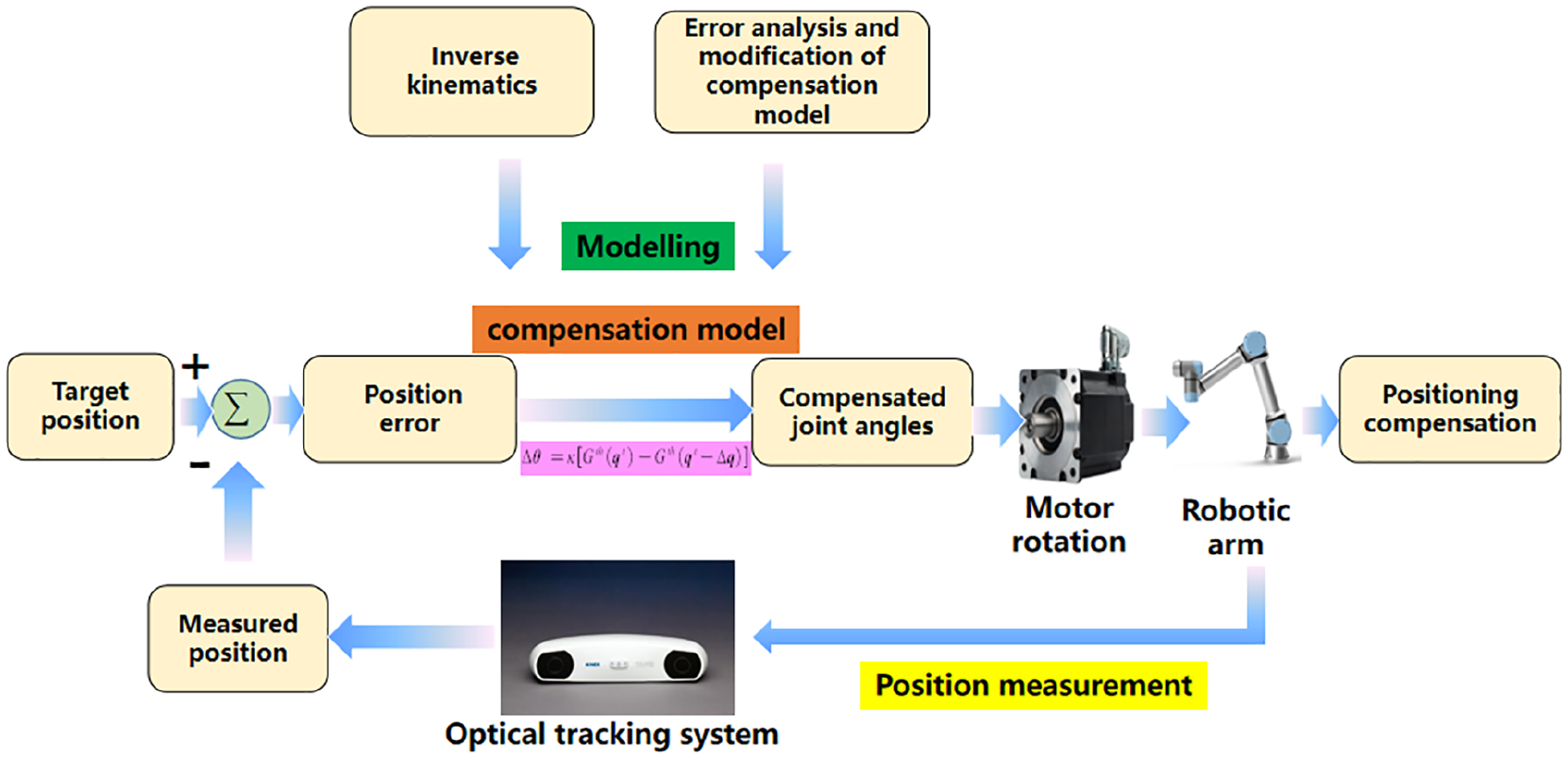
The positioning error compensation method shown in a flowchart.
It is obvious that compensating joint angles is the key idea of PECM for positioning compensation. The model of position error and compensated joint angle in robot systems should be built up and modified based on error analysis. The position error can be calculated with the measured position and the target position, where the measured position can be tracked by the optical tracking system and the target position is guaranteed before experiment for the demand. Moreover, because the position error is obtained by the measured position in optical tracking system, the position error should be converted from the optical tracking system to the robot system.
Thus, the key technologies of positioning compensation based on position errors can be divided into three parts: (a) modeling of the position error and the compensated joint angle in robot systems; (b) error and analysis modification of the compensation model; (c) position error conversion from the measured system to the robot system. The three core parts are the followings:
Modeling of the position error and compensated joint angle in robot systems
Modeling between the position error and compensated joint angle in robot systems is solved based on the inverse kinematics model. Inverse kinematics is an analysis method that joint angles can be solved with known position and orientation of the end-effector. Suppose the position and orientation vector of the end-effector is

Suppose

Suppose the actual and theoretical inverse kinematic operators are respectively

Based on equations (1) and (3),

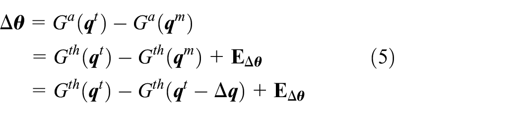
where
Error and analysis modification of the compensation model
To make

It is essential to consider the discrepancy and relationship between

where

Based on equation (8)

Based on equation (5),
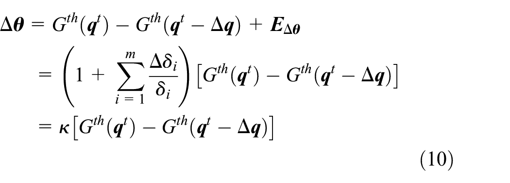
where proportional joint angle compensated coefficient
Position error conversion from the measured system to the robot system
Because the target orientation doesn’t change with the algorithm,

If
According to the above analysis, the accuracy of PECM mainly includes the modeling errors of the position error and compensated joint angle in robot system and position conversion errors from the measured system to the robot system. The former mainly depends on the modeling accuracy of inverse kinematics, while the latter depends on the accuracy of
Experiments
To verify PECM, this paper conducts the positioning accuracy verification experiment based on PECM. To realize the position conversion from the measured system to the robot system, a calibration experiment for

The positioning accuracy verification and calibration system: the passive tool contains four markers numbered in the figure, RCS is the robot coordinate system, OTSCS is the optical tracking system coordinate system.
The system mainly includes: the robot arm, the binocular-vision optical tracking system, passive tool and markers, the controller, and software. As a core device, robot arm is selected from Danish Universal robot arm UR5 with maximum load of 49 N and pose repeatability reaches 0.05 mm. The optical tracking system uses the NDI Polaris binocular-vision system to obtain the real-time measured position of the end-effector. The resolution of the optical tracking system is 0.01 mm. The accuracy 0.25 mm in a large zone ( pyramid volume 1566 × 1312 × 1450 ) and <0.1 mm in a small zone (spherical zone with radius 100 mm). The passive tool attached on the end-effector is a tool for the optical tracking system to track the real-time measured position of the end-effector, that is, the optical tracking system can emit infrared rays to the marker of the passive tool and receive the rays reflected by the marker to obtain the real-time measured position. The controller uses a computer or a robot teaching device combined with software Polyscope to send commands to the robot arm and embed PECM. As shown in Figure 2, the passive tool contains four markers numbered in the figure, and the optical tracking system mainly measure the real-time position of marker 1 to complete the calibration and positioning accuracy verification experiment.
The process of positioning accuracy verification experiment is shown in Figure 3. With the coordinates of target position in the optical tracking system known, coordinates of target position in robot system are obtained through

The process of positioning accuracy verification experiment: OTS means optical tracking system.
The calibration experiment
Calibration experiments aim at deriving the conversion matrix

where

Calibration points in the calibration experiment.
Suppose

Calibration points fitting errors are shown in Figure 5. Suppose

Calibration points fitting errors.
The positioning accuracy verification experiment
The positioning accuracy verification experiment aims to analyze the positioning accuracy of robot arms to verify the effectiveness and rationality of PECM. The experiment is shown in Figure 3, and the experiment system is shown in Figure 2. The experimental procedure is as follows: the motion command sent by the software Polyscope controls the robot arm according to the target position analyzed before the experiment. Simultaneously, after the optical tracking system tracks measured coordinate marker 1 of the robot arm, position errors can be calculated with coordinates of the measured and the target position. The compensated coefficient
The data of the positioning accuracy verification experiment are obtained in a sphere range with a calibration center and radii of 30, 10,2 mm, representing large, medium, small ranges, respectively. In each radius, the data are obtained on the XOY plane, the XOZ plane and the XOY plane rotating 45° around the Y axis, respectively. In each plane, a point is taken by 45°, then there are 8 points (0°, 45°, 90°, 135°, 180°, 225°, 270°,and 315°) in each plane. Considering the conditions of different radii, planes and degrees, there are a total of 72 verification points in the positioning experiment, and verification points in R (radius) 2 is shown in Figure 6.

Verification points in R2.
The resultant positioning error in three directions can be calculated by equation (14), where

To identify the compensated coefficient

Average resultant position errors over different in radii of 30, 10,and 2 mm.
According to Figure 7, position errors of different
The average and maximum positioning error in R2, R10, R30 is shown in Figure 8. After compensation, the average resultant positioning error is 0.34 mm, the maximum is 0.46 mm in R2; the average resultant positioning error is 0.30 mm, the maximum is 0.40 mm in R10; the average resultant positioning error is 0.33 mm, the maximum is 0.47 mm in R30. For different directions, the positioning errors in the X direction are a bit larger than those in the Y direction, and those in the Z direction are the smallest. However, there is no such error fluctuation in different degrees.

The average and maximum positioning error in R2, R10, R30: (a) the R2 average, (b) the R2 maximum, (c) the R10 average, (d) the R10 maximum, (e) the R30 average, and (f) the R30 maximum.
The average positioning errors before compensation (model based on DH), model based on MDH with LM, PECM are shown in Figure 9. The joint angles are solved with the inverse model based on MDH, and the kinematic parameters are identified with the LM algorithm.29,30 The modified parameter of MDH is

Average positioning errors before compensation (model based on DH), model based on MDH with LM and PECM.

The average positioning errors in different directions and radii.
The average and maximum positioning errors in different directions and radii.

From Figure 10 and Table 1, the average positioning errors of R2, R10, R30 are 0.34, 0.34,and 0.35 mm, respectively, and the maximum of R2, R10, R30 are 0.46, 0.45,and 0.47 mm, respectively, reflecting that the errors are almost the same with different radii. The average positioning errors in the X, Y, and Z directions are 0.24, 0.20, and 0.07 mm, respectively, and the maximum in the X, Y, and Z directions are 0.33, 0.35, and 0.22 mm, respectively, reflecting that the positioning errors in Z obviously are smaller than those in the X and Y directions which shows directional sensitivity of positioning errors. The reason is not only directional sensitivity of robot arm caused by mechanical errors (like tolerances of manufacturing and assembly), but also position conversion from the tracking optical system to the robot system, that is the accuracy of transmission matrix
Besides, posture information in robot coordinate system is studied to obtain posture error. Posture information can be obtained with RPY (Roll Pitch Yaw) angle in UR robotic software. By calculating the RPY angle error between target and experimental results in robot coordinate system, the average angle error is in X direction is 0.20°, the maximum is 0.23°, the minimum is 0.16°; the average angle error is in Y direction is 0.06°, the maximum is 0.11°, the minimum is 0.02°; the average angle error is in Z direction is 0.23°, the maximum is 0.28°, the minimum is 0.19°. The average resultant angle error in three directions is 0.31°. The fluctuation of angle error is not large, and the average resultant angle error is relatively small meeting many medical and mechanical applications.
Conclusion
A novel positioning error compensation method based on the measured and the target position error for robot arm is proposed, which improves positioning accuracy of multiple DOF of the robot arm end-effector. Based on the idea of PID to increase robustness and effectiveness of the method, PECM for improving the positioning accuracy of the end-effector mainly includes the modeling of the position error and the compensated joint angle in the robot system, error analysis and modification of the compensation model, and position conversion from the measured system to the robot system. From error analysis, the accuracy of inverse model and the position conversion matrix both influence the accuracy and convergence of PECM. The proportional joint angle compensated coefficient is proposed and identified with position error data to increase the model converging rate, resulting in higher position accuracy further. The position conversion matrix from the optical tracking system to the robot system is derived based on the calibration experiment. The results of positioning accuracy verification experiment show that positioning errors are sensitive to directions, the average resultant positioning error in three directions reduces from 1.89 mm (before compensation, model based on DH), 0.39 mm (model based on MDH with LM) to 0.34 mm (decreasing 82%, 15%), and the maximum error from 2.11, 0.48 to 0.47 mm (decreasing 78%, 2%) which effectively improves the positioning accuracy of the robot arm. It is also shown that the proposed method can be applied in all the multiple DOF of robot arms whose inverse kinematic solution is well structured.
To increase the positioning accuracy further, in the future researchers can focus on the following work. In the view of reducing high directional error sensitivity, the causes of different directional errors will be further analyzed combined with the error directional correlation and filtering algorithm, so as to provide a theoretical basis for further improvement of positioning accuracy. Besides, high-precision angle measuring instrument and angle calibration method will be used to guarantee certain posture for higher positioning accuracy.
Footnotes
Appendix
The compensated joint angles for UR5 in the experiments are expressed as follows in the experiments. As an example, for UR5 in the experiments, based on the inverse kinematics equation and the UR parameters, the angle vector
where
Handling Editor: Chenhui Liang
Declaration of conflicting interests
The author(s) declared no potential conflicts of interest with respect to the research, authorship, and/or publication of this article.
Funding
The author(s) disclosed receipt of the following financial support for the research, authorship, and/or publication of this article: This project is supported by Key-Area Research and Development Program of Guangdong Province (Grant No. 2020B090925002), the joint Research Fund U1813222 between the National Natural Science Foundation of China (NSFC) and Shenzhen (Grant No. U1813222) and National Key Research and Development Program of China (Grant No. 2018YFB1309403).