
Abstract
A kind of internal gear drive with three contact points is presented in the article. Firstly, the pinion with circular-arc form and the internal gear with parabola-circular form are proposed, respectively. General equations of tooth profiles are provided. Furthermore, according to gear geometry, mathematical model of the pinion and the internal gear are generated and their tooth surfaces equations are derived. Meanwhile, based on design parameters, 3D solid models of the new gear pair with three contact points are developed utilizing modeling software. Finally, meshing characteristics of generated new gear pair are analyzed, such as sliding ratios and contact stress conditions. General corresponding comparisons with other internal gear drive are also discussed. Research conclusions show that the new internal gear pair with three contact points has low sliding ratios and high contact strength.
Introduction
As the important mechanical part, internal gears are usually used in planetary gear drive because of the well transmission characteristics. Generally speaking, involute tooth profiles with line contact during design process are commonly tooth profile form. However, the interference effect and tooth profile manufacture are two main problems for practical application.1–2
Lots of researches on performance improvement of internal gears were carried out. Litvin and Fuentes 3 described and analyzed the undercutting and interference problems of the internal involute gear pair during generation and assembly process. Yang 4 determined the tooth profile of internal gear with asymmetric involute teeth, and also present its mathematical model by a double envelope method. Utilizing the Archard wear equation, Tunalioglu and Tuc 5 discussed the influences of tooth profile modification on tooth surfaces wear for internal gears. Cho et al. 6 established the actual tooth contact models with spring elements for internal gears and the structural analysis method was provided by stiffness analysis of gear teeth. Considering the variable rigidity of the meshing gear pair along the contact locus, Sánchez et al. 7 established the bending and pitting calculations load conditions based on a new load distribution model for internal gears. Marques et al. 8 established a basic meshing stiffness analysis model for spur/helical and internal/external gears. Yanase et al. 9 developed a kind of grinding method for internal gears manufacturing through setting a barrel-shaped threaded grinding wheel. Wang et al.10–11 presented a kind of high contact ratio internal gear drive. The mathematical models were established. The characteristics were also evaluated and the results show well transmission performance for the new gears. Chen and Shao 12 researched mesh stiffness of an internal spur gear pair with ring gear rim deformation. The effect of different factors on the mesh stiffness were investigated. Chen et al. 13 present a manufacturing method for straight internal beveloid gear pair by shaper cutter. Mathematical model of the beveloid gear pair were derived. Gui et al.14,15 proposed a mathematical equation of internal compound cycloid gear pair and derived the calculation formula of transverse contact ratio. Otherwise, he also derived the contact analysis models for cycloid internal gear pair with high contact ratio under ideal conditions. To meet the high performance requirements, Mo et al. 16 designed a new type of asymmetric involute internal helical gears and proposed its formation principle of contact tooth profiles.
The authors provided a new single point-contact internal gear form based on curve element. 17 Compared with the meshing condition of single-point contact, generally multi-point contact has the large contact area and better mesh characteristics.18–20 To further improve the load capacity and contact characteristics, a kind of internal gear pair under three contact points condition is proposed. General mathematical model of gear pair is developed, such as the equations of normal tooth profiles and generated tooth surface. Furthermore, 3D solid contact models are established and general simulation analysis is shown to verify the engagement condition. Finally, the meshing characteristics of the gear pair are provided. Also the comparisons between the new internal gears and the involute gears are carried out. This study will provide the useful conclusions for improving the performance of internal gear transmission.
Design principle of new internal gear pair
Normal tooth profile of the pinion
Normal tooth profile form

Normal tooth profile form
The actual contact form

where
And the fillet tooth profile

Specially, in equations (1) and (2), the upper and lower symbols represent separately the left and right sides of tooth profile.
Normal tooth profile of the internal gear
Figure 2 shows normal tooth profile form

Normal tooth profile form
Supposed that l is the distance between B point to any point on line

where

where
Part

where λ1 is the parabolic parameter, and it satisfy
Furthermore, part

where λ2 is the parabolic parameter and it has
Based on the tooth profile analysis, the parts

and

where
Generation of tooth surfaces
General derivation
Here, we establish the coordinate systems
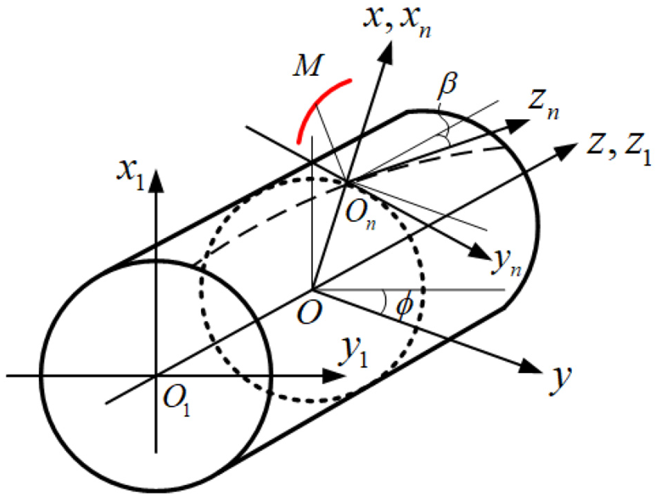
Tooth surfaces generation.
So the transformation relationship between different coordinate systems can be written as follows.


where

So tooth surfaces of the gear can be developed by

Tooth surfaces equation
Substituting equations (1) and (2) to equation (12), separately, tooth surfaces of the pinion are solved as

and
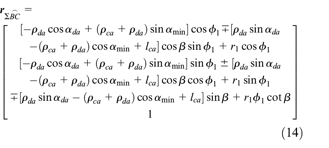
where r1 and
Substituting equations (3)∼ (8) to equation (12), respectively, tooth surfaces of the internal gear are solved as follows.


and
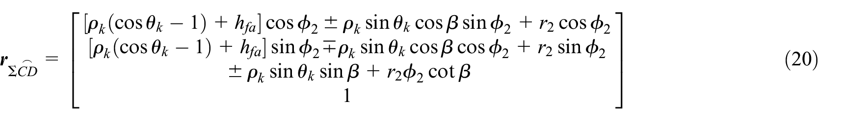
where r2 and
Solid models
Solid models of tooth surfaces are developed by professional software. According to the basic tooth profile parameters determined in Section “Design principle of new internal gear pair” and tooth surfaces equations in Section “Generation of tooth surfaces,” the MATLAB program is developed to solve the related results. Point set of tooth surfaces are obtained using the mathematical calculation function. Further, utilizing the spline curve and surface modeling function in UG, the final tooth surfaces are established. Given the design parameters in Table 1, the 3D solid models of the new gear pair are generated, as displayed in Figure 4.
Design parameters of the new internal gear pair.

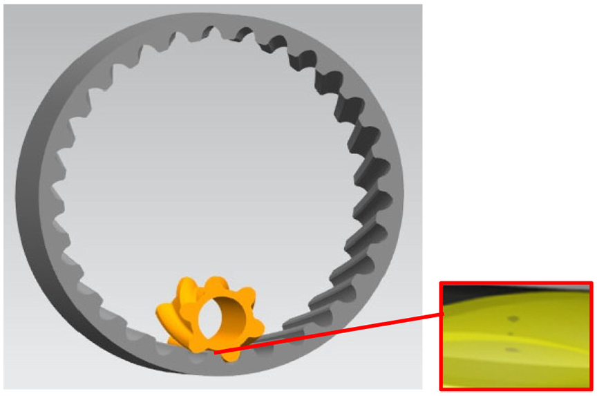
3D solid models of the new internal gears.
Specially, the pinion with small tooth number (z1 = 6) in this numerical example is designed. No tooth surface interference occurs during the meshing process through motion simulation. And three contact points on the mated tooth surfaces always move along the axial direction.
Meshing characteristics analysis
Sliding ratio
Generally speaking, a lower sliding ratio between two mated tooth surfaces will have the higher transmission efficiency. In this paper, we provide the three points contact models of tooth profiles. The set of contact points at any motion process is cylinder helix curve. So we develop the calculation thought of sliding ratios considering the contact locus of tooth surfaces according to its contact essence.
Figure 5 shows the sliding conditions of three points contact surfaces. Supposing that the pinion with contact curve Γ1 transmits motion to the internal gear with the mated contact curve Γ2, they mesh with each other on point W. Δλ1 and Δλ2 are the traveling arcs of contact curves Γ1 and Γ2 after meshing time Δt, respectively. Supposing that there is relative sliding between contact curves, the arc lengths WW1 ≠ WW2, the sliding arc is the difference between Δλ1 and Δλ2. Then the sliding ratios are solved using the following calculation formulas.

where

Sliding conditions of contact surfaces.
Based on the theoretical derivations by Liang et al., 22 the equations of contact curves, that is, the spatial cylinder helix curves, on the mated internal gear pair can be obtained. We solve the sliding ratios results shown in Figure 6(a) using the parameter data in Table 1. The sliding ratios results always maintain constant conditions if the contact curve parameter θ changes. The sliding ratios values are calculated as ±0.08 closed to 0 and there is the approximate pure rolling condition along the axial direction between the new gear pair.
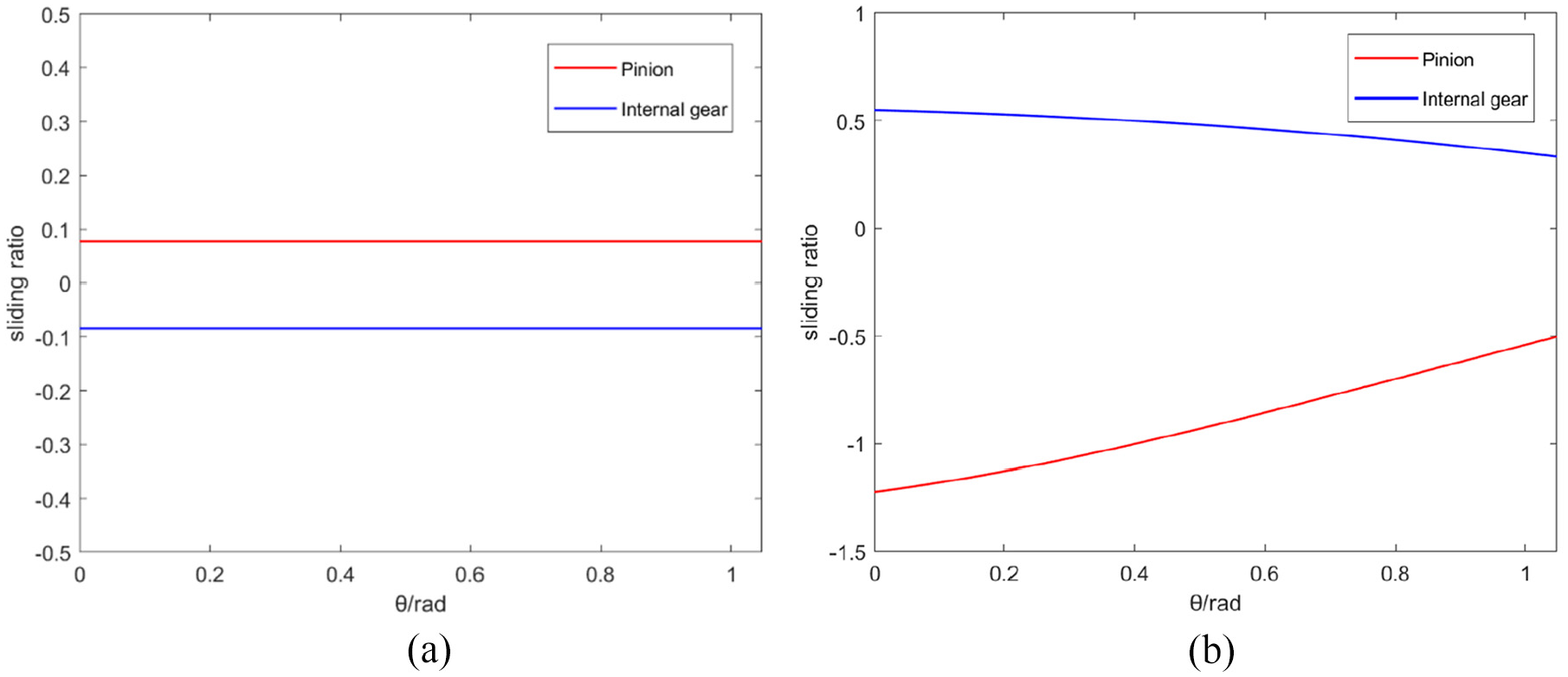
Sliding ratios of contact tooth surfaces: (a) the developed internal gears and (b) the general involute internal gears.
Utilizing the same analytical parameters, sliding ratios of the general involute internal gears are also solved for comparison. The results are displayed in Figure 6(b). Obviously, if the parameter θ changes, the sliding ratios results are variable and they will reach the value 0 at pitch point. Compared with the new internal gear pair, there is the greater relative sliding between tooth surfaces.
Stress analysis
Finite element method will be used in this section to analyze the actual contact stress. Here, we provide three kinds of different gear pair: single contact point condition, the three contact points condition, and the involute contact condition.
After finishing the establishment of solid models under the same parameters, the FEM software Work Bench 18.0 is used for calculation. Element solid 186 is considered as the general mesh form. The number of contact elements is 90,720 and the number of nodes is 393,890. The pinion and the internal gear are separately considered as the contact and target object. The material is 40Cr with the properties of Young’s Modulus E = 206 GPa and Poisson’s ratio λ = 0.3.
We use the asymmetric contact method and set the friction coefficient to 0.12. Based on the method of elastic theory, finite element models of three kinds of internal gear pair are processed. The input load torque is 200 Nm on the inner diameter of the pinion. The general analysis model with single tooth is shown in Figure 7.

Contact analysis model with single tooth: (a) meshing pair and (b) conditions setting.
Figure 8 shows the analytical results of internal gear pair under single point contact condition. The meshing area of gear pair which is elliptical form occupies about 1/2 working tooth height. The long-axis direction of the ellipse is tooth width direction. The maximum value of contact stress is 1266.5 MPa and it appears on the design position of tooth profile. The maximum values of the von Mises stress of the pinion and the internal gear are 793.69 and 984.14 MPa, separately. The maximum values of shear stress of the gear pair are 411.69 and 371.45 MPa, respectively.

Analytical results under single contact point condition (unit: MPa): (a) contact status, (b) contact stress, (c) von Mises stress of the pinion, (d) shear stress of the pinion, (e) von Mises stress of the internal gear, and (f) shear stress of the internal gear.
Figure 9 shows the analytical results under three contact points condition. Contact region is almost the entire working tooth height, which is oval with a small upper part and a large lower part. The maximum value of contact stress is 923.26 MPa. The maximum value of the von Mises stress of the gear pair are 449.1 and 928.02 MPa. The maximum value of shear stress of the gear pair are 157.5 and 266.93 MPa, respectively.

Analytical results under three contact points condition (unit: MPa): (a) contact status, (b) contact stress, (c) von Mises stress of the pinion, (d) shear stress of the pinion, (e) von Mises stress of the internal gear, and (f) shear stress of the internal gear.
Figure 10 shows the analytical results of the involute internal gear pair. Obviously, its contact locus of gear pair is a skew line, and the maximum value of contact stress happening on the position of tooth top is 1639 MPa. The maximum value of the von Mises stress of the gear pair are 1234 and 806.16 MPa. The maximum value of shear stress of the gear pair are 107.39 and 155.34 MPa, respectively.

Analytical results of involute internal gear pair (unit: MPa): (a) contact status, (b) contact stress, (c) von Mises stress of the pinion, (d) shear stress of the pinion, (e) von Mises stress of the internal gear, and (f) shear stress of the internal gear.
The comparison analytical results under three kinds of contact conditions are displayed in Table 2. The maximum value of contact stress under three contact points condition is 27.1% and 43.7% lower than that of the internal gear pair under single contact point condition and under the involute contact condition, respectively. The shear stress and von Mises stress of tooth surfaces of the developed gear pair under three contact points condition are also improved. The analytical results are beneficial for the improvement of transmission characteristics. The further study for the dynamic analysis and key manufacturing technology will be carried out. This gear drive is expected to have excellent transmission performance.
Stress analysis results of three kinds of contact conditions.

Conclusions
We propose a kind of internal gear drive with three contact points. For the pinion, theoretical tooth profile including the actual meshing part and fillet part are proposed. Similarly, for the internal gear, tooth profile including different line segment, circular-arc part, and parabola part are also provided. The general equations of tooth profiles are written, which lay the important foundation for generation of tooth surfaces.
According to gear geometry theory, generation method of general tooth surfaces is put forward. Utilizing aforementioned normal tooth profiles, the final contact tooth surfaces of the pinion and the internal gear are developed, respectively. General expressions of the new internal gear drive are derived.
Numerical example of the developed internal gear pair under three contact points condition is provided. Actual tooth surfaces are established through 3D modeling software UG and mathematical calculation software MATLAB by the given design parameters. Furthermore, the 3D solid models of the gear pair are developed. The pinion with small tooth number is designed and it shows the ideal transmission conditions based on motion simulation.
Sliding ratios of tooth surfaces of the new gear pair are calculated based on the derived conclusions. And the comparison with involute internal gear pair under the same parameters is also discussed. Discussion results show that the approximate pure rolling condition between the new gear pair in the axial direction will happen. Furthermore, the stress analytical process of the generated tooth surfaces is conducted by FEM. The comparison results show that the maximum value of contact stress of the new gear drive is lower than that of other two gears. The shear stress and von Mises stress of tooth surfaces are also improved. The analytical results are beneficial for the improvement of transmission characteristics. Further study on meshing performance and dynamics property will be carried out.
Footnotes
Handling Editor: Chenhui Liang
Declaration of conflicting interests
The author(s) declared no potential conflicts of interest with respect to the research, authorship, and/or publication of this article.
Funding
The author(s) disclosed receipt of the following financial support for the research, authorship, and/or publication of this article: This work was supported by the National Natural Science Foundation of China (Grant No. 52175042) and Chongqing Key Laboratory for Public Transportation Equipment Design and System Integration Open Fund (Grant No. CKLPTEDSI-KFKT-202102).