
Abstract
Static steering torque at parking is an important factor for steering portability of vehicle. At present, the most commonly used estimation method is empirical formula calculation, which, however, cannot explain the phenomenon that the steering torque increases rapidly when steering angle becomes very large (over 300°). This article proposes an estimation method of static steering torque on the basis of a mathematic model of tire-patch sliding torque, taking into account the changeable torque transmission ratio from steered wheel to steering wheel. Three components of static steering torque are modeled and analyzed, including the tire-patch sliding torque, gravity aligning torque, and internal friction torque of the steering system. In order to investigate the static steering torque at steering wheel, the transmission ratio of steering torque is obtained on the basis of rack-suspension mathematical analysis. An example of static steering torque estimation is conducted with the proposed method and is compared with experimental results. The comparison shows that the estimation results given by the proposed method are in better accordance with experimental results than other approaches.
Keywords
Introduction
Vehicle steering performance can be described in two general ways, that is, steering stability and portability. Steering stability indicates vehicle stability during steering,1,2 while the steering portability refers to the ability of steering at parking or low speed when steering torque is at its highest in steering maneuvers.3,4 For steering stability, many tire models including the magic formula model have been used to investigate tire force distribution, especially the lateral force during driving.5–8 However, few tire models or estimation methods for investigation of static steering torque have been proposed to study the steering portability. At present, static steering torque is mostly calculated by empirical formula, assuming that the tire–road contact patch is similar to a circle.9,10 However, the tire–road contact patch is much closer to a rectangle for radial tire,11–13 and the assumption of a circular tire–road contact patch usually gives a large computation error when used to calculate the static steering torque of radial tire.
Static steering torque is a key component for assist characteristic design of power steering system, 14 which determines the drivers’ steering portability on parking. However, the static steering torque model presented by empirical formula, which is adopted to design static power steering characteristic, 15 has low accuracy and often results in bad feeling in static steering maneuvers. Automatic parking systems, such as parking assistance system (PAS),16,17 the advanced parking assistance system (APAS), 18 and autonomous valet parking (AVP),19,20 are all low-velocity system, and most of the researches focus on the path design and control of parking,16–21 but the realization of automatic parking needs precision control of steering motor, and an accurate static steering torque model is therefore necessary for parking motor control. The parking system of intelligent vehicle is similar to automatic parking system. 22 Without supervision and participation of the driver, the parking motor control needs more precise static steering model. The power steering system and automatic parking system mentioned above are basic systems in modern automobile; the importance of static steering torque for these systems makes the study of static steering a focus in the field of steering studies. In addition, the tire steering torque during the process beginning from vehicle’s start to the time it reaches a low velocity (about 10 km/h) has been a difficult problem, 23 and precision static steering model contributes to the investigation of this issue.
Static steering torque is usually described by the feedback of steering wheel torque, which includes the internal friction torque of steering system, the gravity aligning torque generated by vertical force, and the tire-patch sliding torque (tire-patch sliding torque is the sliding torque acting on the tire–road contact patch). 9 The tire-patch sliding torque is usually regarded as static steering torque for simplicity because it accounts by far for the largest proportion of it. Static steering torque increases linearly in traditional calculation, 24 but the actual steering torque increases rapidly when steering angle becomes very large (over 300°). The reason is that the traditional method does not take into consideration the change of torque transmission ratio from steered wheel to steering wheel. Because of the large steering angle in static steering maneuver, the torque transmission ratio experiences a big change, which cannot be ignored.
Aiming at studying the static steering torque, tire-patch sliding torque on the basis of rectangular contact patch assumption is analyzed in this article. The gravity aligning torque is analyzed, and the internal friction torque of steering system is also measured. The transmission ratio from steered wheel to steering wheel is estimated in order to obtain a more precise value of the torque. In section “Static steering torque model,” the static steering torque is investigated, including the tire-patch sliding torque and gravity aligning torque. The transmission ratio is investigated on the basis of mathematic and kinematic analysis of steering system in section “Transmission ratio of torque.” The estimation method and results of static steering torque are given in section “Static steering torque estimation and test results,” including the comparison of estimation results and test results. The conclusion is given in the final section.
Static steering torque model
Tire-patch sliding torque model
In order to estimate the tire-patch sliding torque, some assumptions are given as follows:
The point of tire–road contact patch center moves around the kingpin–ground intersection point;
Kingpin positional parameters are assumed to be unchanged during steering maneuver;
Tire–road contact patch shape is rectangular. The studies of Schmitt, 9 Nagasaka et al., 11 and Roos 12 adopt the rectangular tire–road contact patch to do their research, and the Zhuang 13 collects the shape of tire–road contact patch and points out that the patch is closer to a rectangle than a circle.
The tire model with parabolic distribution pressure is used in this study, which is shown in Figure 1. The pressure distribution in tire–road contact patch is a parabolic11,12,25

where a and b are the contact patch length (x-direction) and width (y-direction), respectively, and Fz is the vertical load applied to a steered tire.

Distribution of pressure in tire–road contact patch.
Length a and width b of contact patch can be obtained by empirical formulas 13


where s and t are the radial tire empirical coefficient, whose values are 0.557 and 122.7, respectively. B0 is the width of tire crown, D is the diameter of tire, δ is the radial deformation, and e is the base of natural logarithm.
The radial deformation δ is given by Zhuang 13
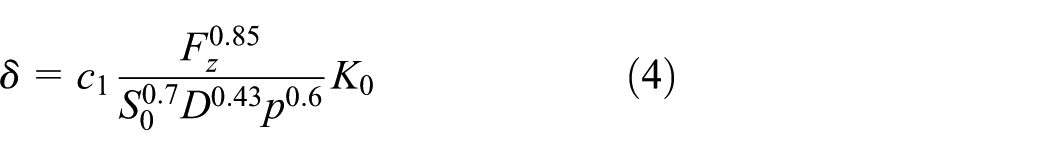
where c1 is the parameter of tire design, whose value can be set as 1.5. S0 is the width of tire section and K0 is the function of S0 in that
The movement of tire can be divided into two processes in static steering: tire elastic deformation phase and tire–road contact patch sliding phase. As shown in Figure 2, tire angle is greater than tire–road contact patch angle for the reason that tire will act as a torsional spring, in which kingpin angle is greater than the actual tire angle. In Figure 2, xbyb is the vehicle-based coordinate system, xtyt is the tire coordinate system, xtpytp is the tire–road contact patch coordinate system, Φkp is the kingpin angle that can be determined by steering wheel angle, and Φtp is the tire–road contact patch angle. 12

Relations between body, rim, and tire–road contact patch coordinate system.
The carcass will turn several degrees in tire elastic deformation phase before the tire–road contact patch begins to slide. The elastic deformation angle γ is given by

In elastic deformation phase, tire can be treated as linear elasticity, and its stiffness can be recorded as Ks. The movement of sliding is shown in Figure 3. The tire–road contact patch center rotates around the kingpin–ground intersection. In order to analyze the sliding torque, the coordinates are assumed to be fixed on the tire–road contact patch. xy and x′y′ are the coordinate systems before and after the tire–road contact patch begins to slide, O1 is the kingpin–ground intersection, O is the point of tire–road contact patch center, df is the friction force of an infinitesimal element in the contact patch, rkp is the arm of surface element, and e0 is the distance from the kingpin–ground intersection to the contact patch center.
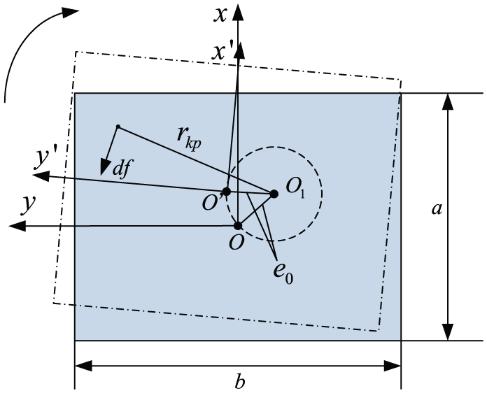
Tire–road contact patch sliding.
The torque of every element (in the coordinate system x′y′) about kingpin–ground intersection is given by

where µ is the friction coefficient, which is difficult to be measured directly but it is possible to be determined by the treadwear TW. The relation between concrete (dry) friction coefficient and the treadwear from 2002 to 2010 was studied by Tire Rack, which is a tire distributor in North America. 26 The values of maximum friction coefficient and minimum friction coefficient are within 10% of the theoretical value, which can be calculated by

The total torque is the sum of friction torque of all elements

The length of the arm rkp is given by

Figure 4 illustrates the movement trajectory of O shown in Figure 3, β is the angle that is determined by the position of kingpin–ground intersection, and O′ is the contact patch center after a certain amount of sliding. ex and ey in equation (9) can be obtained from Figure 4


A circular motion around the kingpin–ground intersection.
Tire–road friction torque can be obtained by equations (8) and (9)

where x0 = −a/2, x1 = a/2, y0 = −b/2, and y1 = b/2.
The torque of tire–road contact patch that slides around the kingpin–ground intersection can be obtained by equation (12). The tire-patch sliding torque is given by

where σ and τ are the kingpin inclination angle and caster angle, respectively.
Equation (13), which can give tire-patch sliding torque, is different from the analysis made by Roos. 12 In the study of Roos, 12 the tire-patch sliding torque varies with the steered wheel angle and is larger than tire–road friction torque. However, according to the principle of static torque generation,15,27 the tire-patch sliding torque cannot be larger than tire–road friction torque. And it is obvious from equations (10) and (11) that ex and ey remain constant as steered wheel angle varies, which means tire-patch sliding torque is constant as steered wheel angle varies.
Gravity aligning torque model
The vertical force Fz will generate a torque which resists the steering movement of steered wheel. As shown in Figure 5, gravity aligning torque is determined by kingpin inclination angle σ, kingpin caster angle τ, and tire angle δt.15,27rs is the kingpin offset and Mz is the torque along z-axis. Figure 5 shows that the generation of gravity aligning torque ignores tire camber angle and toe angle.

Generation mechanism of gravity aligning torque.
Gravity aligning torque is given by

Summary of static steering torque
The static steering torque is analyzed in this section, including the tire elastic torque, tire sliding torque, the gravity torque, and the internal friction torque of steering system. Vehicle static steering torque can be written as follows
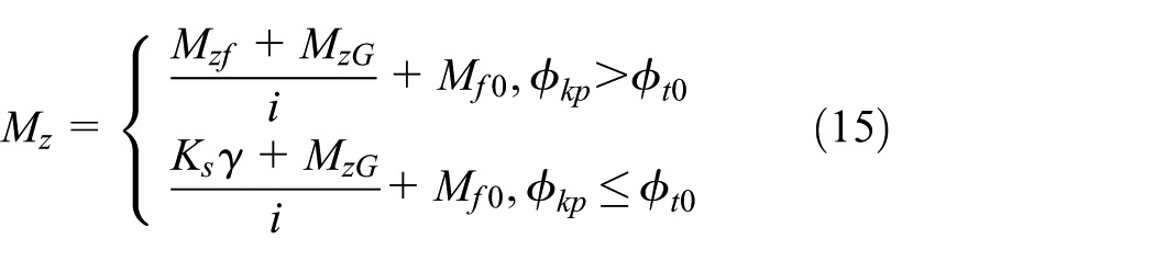
where i is the transmission ration of torque, Mf0 is the internal friction torque of steering system, which is represent in section “Static steering torque estimation and test results.”Φt0 is the threshold of elastic angle of tire. And the elastic Ks can be written as follows

where γmax is the elastic deformation angle when the tire starts to slide.
Transmission ratio of torque
The torque transmission ratio from steered wheel to steering wheel will change with steering angle; therefore, the feedback of static steering torque on steering wheel needs to be refined by the variable torque transmission ratio. In this section, the steering torque transmission ratio is investigated on the basis of the kinematic analysis.
Steering system is spatial structure whose kinematic relations are highly complex, but Z-axis has little effect on the change of tire angle during cornering. In order to analyze the torque transfer, some assumptions about rack-suspension transmission system are given as follows:
Three-dimensional (3D) space can be converted into two-dimensional (2D) plane when the effect of Z-axis is not considered;
Components of steering mechanism are rigid;
Rack movement is a motion of translation. Rack-suspension transmission system is simplified into the single-freedom system;
The virtual rotation center is taken as the center of wheel rotation.
The intersection between the straight line of kingpin and driveshaft can be used as wheel rotation center based on assumptions mentioned above. The real car hard spot point data of wheel rotation center, inner point, and outside point of tie rod are used to project the locations of the objects on a 2D piece of paper. The motion of rack-suspension transmission system during a turn is shown in Figure 6.

Mathematical model of kinematics for rack-suspension transmission system.
With the hard spot point data of a real vehicle suspension known, the length of knuckle arm Lk, tie rod Lt, and the distance Lrk from the intersection of rack and tie rod to the intersection of knuckle arm and kingpin can be easily obtained. The angle θrtl, θrkl, θtkl, and θ2 are also easily available when steering wheel is in central position. The left-side parameters are analyzed and the right-side parameters can be obtained using the same method.
Rack covers a distance of xr when steering wheel turns a certain angle (assuming that wheels turn right)

where θ is the steering wheel angle and R is the radius of steering gear.
The left distance

Tire angle is a result of the rotation of knuckle arm

where δl are left tire angle. θ1, θ2, and θ3 can be obtained based on cosine

To demonstrate the validity of rack-suspension transmission system mathematics model, the experiment is carried out. Based on the dynamic analysis of steering system, the transmission curve of steering angle is obtained. Figure 7 illustrates the theory and experimental results of transmission curve. It shows that angle of inner steered wheel is larger than the outside one in steering. The theoretical results are consistent with the experiment in the scope of experiment steering angle. The difference between theoretical results and experimental ones becomes slightly larger with the increase in steering angle. The largest error is only 1.76%, which appears at the maximum steering angle. Therefore, the rack-suspension transmission system mathematics model can be used in the analysis of torque transmission ratio.
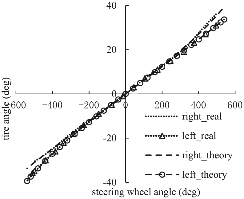
Curve of left and right wheels angle.
In order to obtain torque transmission ratio, rack–tie rod angle and tie rod–knuckle arm angle need to be calculated.
The calculation results of rack–tie rod angle and tie rod–knuckle arm angle are shown in Figures 8 and 9. The “inner” and “outer” are relative to steering; the inner is the left when steering wheel turns left. Figure 8 illustrates that the rack–tie rod angles of inner and outer are decrease with steering angle, and the decrease in inner is more than the outer. In Figure 9, the tie rod–knuckle arm angle of outer is also decrease with steering angle, but the changing trend of inner is opposite to the outer.
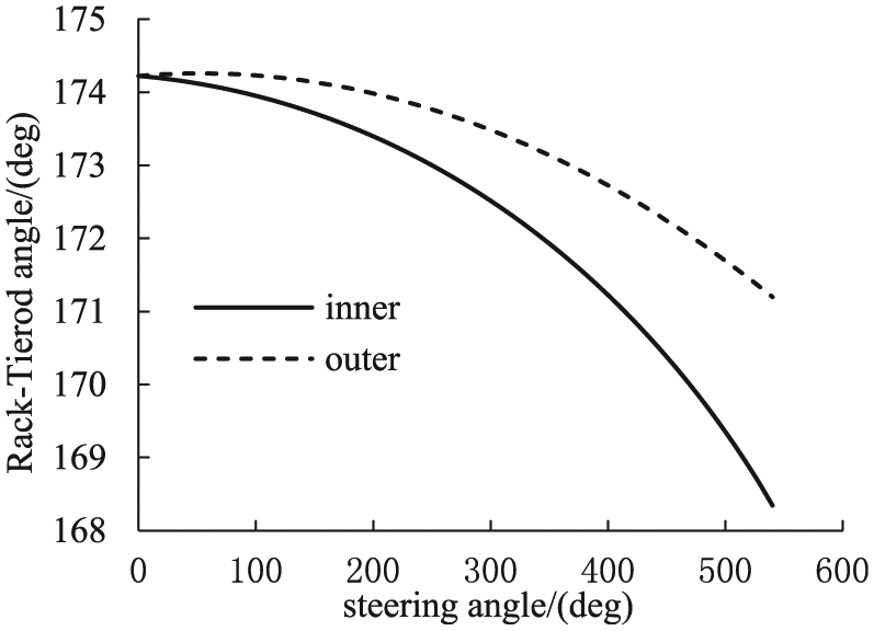
Angle between the rack and the tie rod.
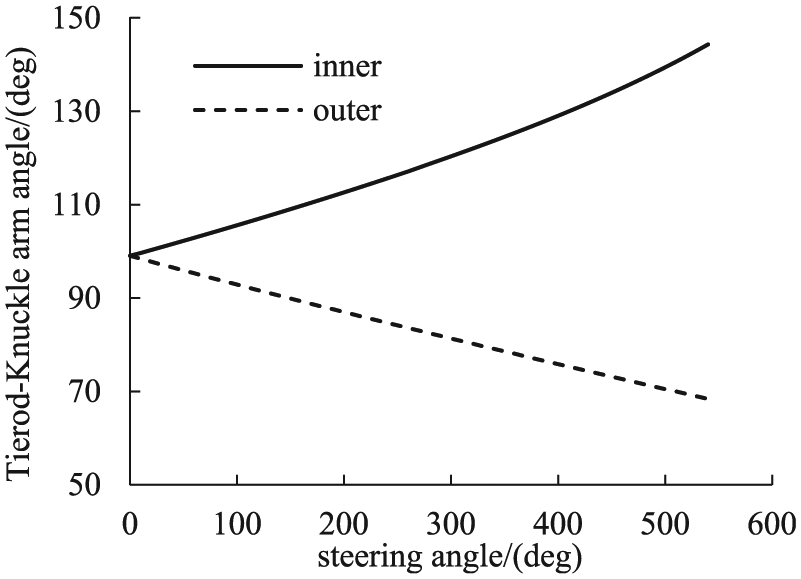
Angle between the tie rod and the knuckle arm.
The torque transfer in transmission mechanism is shown in Figure 10. In Figure 10, Frt is the force of rack, Ftt is the force of tie rod, L is the arm of the tie rod force that acts on kingpin, and Pk is the wheel rotation center. The direction of Z-axis is upward in vehicle coordinate system.

Model of torque transfer.
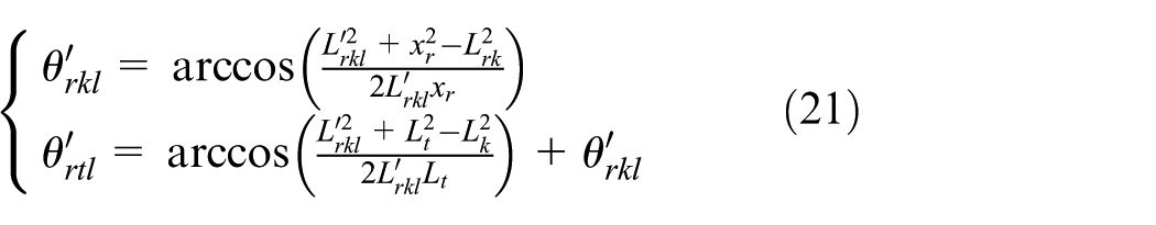
In the model of torque transfer, θrt is the angle between rack and tie rod, θtk is the angle between tie rod and knuckle arm, and θkk is the angle between knuckle arm and kingpin. The transmission ratio is given by

where Lk is the length of knuckle arm, and θkk is a constant,
Figure 11 illustrates the calculation results of torque transmission ratio of the inner and outside of steered wheel. The transmission ratio of inner steered wheel decreases with the increase in steering angle. The transmission ratio of outside steered wheel first increases slightly and then decreases with the increase in steering angle. The entire transmission ratio follows the same trend with inner transmission ratio; however, the former decreases slower than the latter.

Torque transmission ratio.
Static steering torque estimation and test results
As shown in equation (15), the torques Mf0 and Mzf, which are relative to static steering torque, need to be analyzed and verified. Then, static steering torque can be obtained and compared with the test results.
Internal friction torque of steering system
In estimating the static steering torque on steering wheel, the internal friction torque of steering system, whose direction is contrary to the direction of front tire steering, cannot be ignored. This friction torque is hard to be analyzed, and it can therefore be measured from the experiment.
For measuring the steering system friction torque, a steering plate is used, which is shown in Figure 12(a). The static steering torque includes the internal friction torque of steering system Mf0, gravity aligning torque MzG, and the friction torque of steering plate Mp when it is measured with the plate

where Th_wp is the static steering torque when measured with steering plate, which can be measured by steering dynamometer.

Static steering torque test: (a) with plate and (b) without plate.
To get the accurate internal friction torque Mf0, the friction torque Mp needs to be obtained. The mechanical structure diagram is shown in Figure 13. There are n rolling-balls in the steering plate, and the n balls share the vertical load FG equally. It is assumed that the coefficient µp of rolling resistance do not change with vertical load, the friction fsrb of single ball is as follows


Mechanical structure of steering plate.
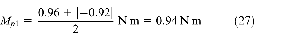
The friction torque Mp1 of steering plate is given by

where r is the distance from rolling-ball to plate center.
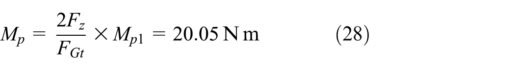
The torque Mp1 is proportional to the vertical load FG based on formula (25), the friction torque Mp (front axle load 2Fz) can be obtained by the torque Mp1 (test load FGt)

A regular weight should be placed on the steering plate first when measuring the torque Mp1, and the axis of this weight to a horizontal plane is vertical. The spin axis of steering dynamometer installed on the weight should overlap with the axis of this weight. The test devices and results are shown in Figure 14.
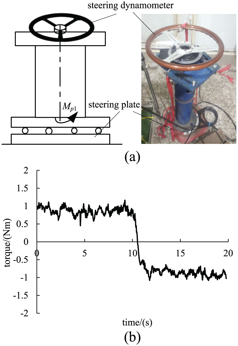
Test devices and test results for Mp1: (a) test devices and (b) test results.
In terms of Figure 14(b), the friction torque of steering plate with test load basically remains unchanged, and the averages of clockwise and counterclockwise friction torques are 0.96 and −0.92 N m, respectively. The friction torque Mp1 is given by
The torque Mp with front axle load is as follows
The measurement results of steering torque with plate are given in Figure 15. The gravity aligning torque is zero and the transmission ration is a constant when steering angle is zero. The internal friction torque of steering system is given by

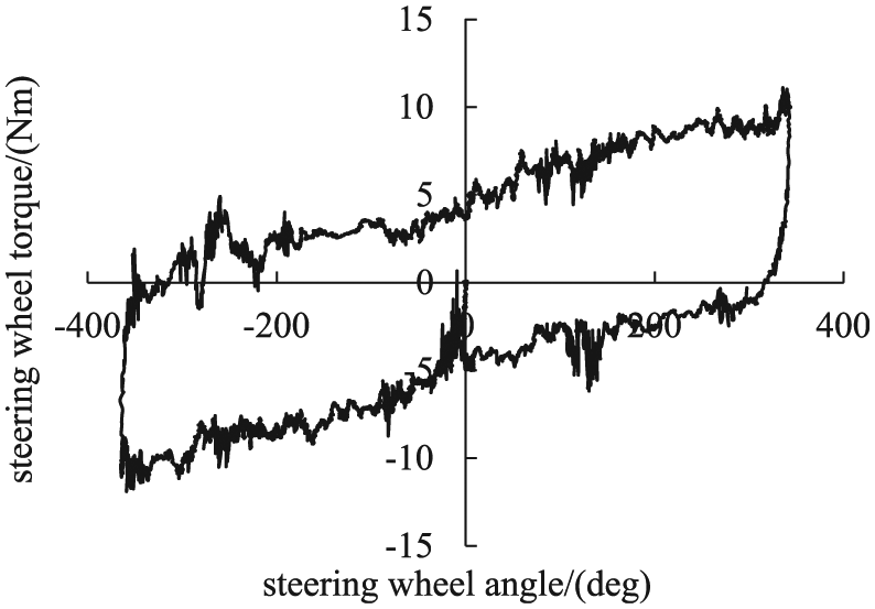
Steering wheel torque with plate.
Verification of tire-patch sliding torque model
The vehicle parameters used in tire-patch sliding model are shown in Table 1. In measuring static steering torque without plate illustrated in Figure 12(b), the static steering torque includes the internal friction torque of steering system Mf0, the gravity aligning torque MzG, and the tire-patch sliding torque Mzf. Therefore, the tire-patch sliding torque can be obtained by the static steering torque with and without plate

where Mzf_sw is the tire-patch sliding torque on steering wheel, and Th_wop is the measured value of static steering torque without plate. The test results and calculation results are given in Figure 16.
Parameters of vehicle.

Verification of tire-patch sliding torque model.
The torque difference illustrated in Figure 16 is the torque Mzf_sw, and the torque portrayed by “Δ” is the tire-patch sliding torque calculated by equation (13) and variable transmission ratio. From Figure 16, it can be seen that the Mzf with variable ratio well matches the torque Mzf_sw. Therefore, the proposed tire-patch sliding torque model can be used to describe the mechanism of tire sliding on road.
Static steering torque test
The scheme of static steering torque estimation is shown in Figure 17. And the calculation and experimental results illustrated in Figure 18 show that static steering torque increases with steering angle: it increases linearly when calculated by traditional empirical formula method or others without modification by transmission ratio, while it increases nonlinearly with the proposed method in this article.

Scheme of static steering torque.

Comparison of static steering torque between model and real vehicle.
From Figure 18, it can be seen that the estimation results of empirical formula are larger than the experiment ones in region of small steering angles, but they become smaller in region of large steering angles. This phenomenon illustrates that the empirical formula has large error in estimating static steering torque of radial tire, whose tire patch is more similar to a rectangle. The estimation results, which are described by “uncorrected curve” in Figure 18, are calculated by equation (15) with constant transmission ratio. The results are closer to the experimental results in small steering angle region (in Figure 18, less than 300°); however, it has a large error in large steering angle region and cannot describe the nonlinear character because in nonlinear region the slope of static steering torque rises markedly in large steering angle region.
The estimation results with the method proposed in this article portrayed by “o” fit in well with experimental results from the small steering angle to the large steering angle, and the sharply rising slope of large steering angle region is also accurately described. The estimation and experimental results are more or less consistent when steering wheel rotates in reverse direction. The probable reasons are that the friction coefficient changes, which are assumed to be constant in our model, or the road surface roughness of two steered wheels are different.
The reasons for the errors of different static steering models are given as follows:
The tire patch of empirical formula is similar to a circle, but the tire patch of radial tire, which is widely used presently, is similar to rectangle.
A small error arises in the principle of static torque generation in the study of Roos; 12 thus, the estimation static steering torque is larger than the real torque in small steering region.
The variable ratio is not considered in the estimation method described by “uncorrected curve,” and the real transmission ratio decreases markedly with the increase in steering angle.
The estimation method proposed in this article considers the rectangle tire patch and the variable transmission ration; therefore, it fits in well with experiment than the other method.
Conclusion
In this study, an estimation model of static steering torque is constructed, including gravity aligning torque and tire-patch sliding torque. The analysis of tire-patch sliding torque is based on the assumption that tire–road contact patch is rectangular instead of being circular. And then this model is further refined by variable transmission ratio and compensated by the internal friction torque of steering system. With the proposed method, a nonlinear curve of static steering torque is obtained, which proves to be in better accordance with the real vehicle static steering torque, and explains the phenomenon of sharp increase in steering torque when steering wheel angle becomes very large (over 300°). The research of static steering torque in this article takes into account the change of torque transmission ratio, which can be obtained on the basis of 2D rack-suspension mathematical model. In this way, the proposed method gives a more precise description of static steering torque, which has significant meaning for assist characteristic design and parking assistance motor control. And the proposed method can also promote the quantitative study of vehicle steering torque in low-speed region.
Footnotes
Academic Editor: Crinela Pislaru
Declaration of conflicting interests
The author(s) declared no potential conflicts of interest with respect to the research, authorship, and/or publication of this article.
Funding
The author(s) disclosed receipt of the following financial support for the research, authorship, and/or publication of this article: This work is partially supported by National Natural Science Foundation of China (51375009 and 51575223) and Tsinghua University Initiative Scientific Research Program (2014z21039).