
Abstract
The periodic and impact excitations caused by drum winding and interface misalignment of steel guides always result in hoisting instability in mine shafts. This paper focuses on investigating the longitudinal response of the lifting system subjected to the two disturbance excitations. First, the periodic velocity and acceleration excitation from an experimental model was derived. Second, the virtual prototype model for the longitudinal vibration of the hoisting rope subjected to the two excitations was built in ADAMS, and the validity of the established virtual prototype model was verified experimentally. Eventually, the acceleration of the conveyance under the disturbance excitations were effectively reduced by applying a vibration reduction device, and the virtual simulation results confirmed the effectiveness of the proposed device. This paper can provide a good scheme for the research of vibration reduction in mine hoisting systems.
Introduction
A winding mine hoisting system is always composed of Lebus drum, catenary, head sheave, hoisting rope, conveyance and rail guide system, etc., as shown in Figure 1. Under the background of the super deep mine hoisting systems, the length of steel wire rope often exceeds 1500 m. One end of the rope connected to the Lebus drum will subject to the disturbances of periodic displacement, velocity, and acceleration due to that the Lebus drum has the special parallel groove structure. The other end of the steel wire rope is often connected with the lifting container which rises steadily along the steel guide through steel rollers. However, interface misalignments of the steel guides will cause impact excitations due to improper manual installation or other reasons. The above excitations will cause abnormal vibration of the hoisting rope and lifting conveyance, and even lead to accident such as tank jamming and rope rupture, which will absolutely threaten the safety of mine hoisting. Thus, it is of vital importance to study the vibration response of hoisting rope under different disturbances.

Schematic of winding mine hoist.
Many researches have investigated the vibration characteristics of steel wire rope in lifting systems. Li et al.1,2 have built simplified virtual prototype model of friction mine hoist based on relative node method and predicted cable tension and cage acceleration by utilizing this model under different velocity, acceleration, frictional coefficient of friction mine hoist. Wang et al. 3 have studied the longitudinal vibration of parallel hoisting system with tension auto balance device attached to the ends of all hoisting rope and carried out the ADAMS simulation to verify the numerical solution. Wang et al.4,5 have also discussed the dynamic response of cable-driven parallel sinking platform considering the longitudinal-torsional coupled characteristics of the cable through Lagrange equations and carried out the ADAMS simulation. Wang et al. 6 have improved a simulation method for investigating the vibration behavior of hoisting rope with time-varying length in ADAMS. The references above mainly focus on the vibration behavior of wire rope in ADAMS simulation without involving experimental verification.
As a large-deformation body with variable stiffness and length, it is not enough to investigate its dynamic response by simulation only. In recent years, many scholars have analyzed the dynamic response of steel wire ropes based on experiments. Guo et al.7,8 have studied the longitudinal rope dynamics in the friction hoisting system and its coupling effect with friction transmission, and obtained longitudinal vibration characteristics of steel wire rope along with the effect of wore rope transverse vibration on friction transmission stability through ADAMS simulation and experimental device. Wu 9 conducted experiments on a winding hoisting platform and obtained the transverse vibration response of the catenary and compared the results with numerical simulation. Arrasate et al. 10 have addressed the influence of torque fluctuation of elevator power system on longitudinal vibration of elevator system, and the numerical simulation results are compared with the experimental results. Jiahai et al. 11 have investigated the longitudinal response of a ground mounted friction hoist under normal braking and constant-deceleration emergency braking. Besides, some researchers have paid attention to different disturbance excitations during the lifting process. Peng et al.12,13 have discussed different dynamic responses of the hoisting system when the wire rope winds on symmetrical or asymmetrical grooves while neglecting the longitudinal oscillations. Wu 14 has built an experimental platform to analyze the vibration response of conveyance under different steel guide faults, and the influence of different faults on the vibration characteristics of conveyance with different velocities and lifting weight. Xiao and Li15,16 have established the vibration model of conveyance moving in the steel guide, discussed its fault mechanism, and conducted experiments to obtain the vertical and horizontal vibration of the lifting cage under steelwork misalignment. Lin 17 has analyzed the steel guide and conveyance response under steel guide irregularity using the method of theoretical analysis and numerical simulation, and obtained the variation rules of vibration response with amplitude of irregularity, lifting speed, and terminal load.
Nevertheless, there are few reports on the effect of fluctuating hoisting velocity and acceleration caused by drum winding. Also, the longitudinal vibration of the cable under different kinds of steel guide faults should be paid more attention to because impact faults such as interface misalignment will cause abrupt dynamic force along the axis direction of the cable, resulting in shorter service time of the rope and potential safety hazard. Therefore, the longitudinal vibration of the hoisting system under disturbance excitations should be discussed, and the corresponding measures should be proposed to lessen its oscillation.
In this paper, a mathematical model of the simplified winding process of the hoisting rope on Lebus drum was built and the coupling model of hoisting rope subject to drum winding and interface misalignment of the steel guide were established based on ADAMS in section “Establishment of Virtual prototype.” In section “Experimental validation,” an experiment was performed to verify the correctness of longitudinal vibration model of hoisting rope. In section “Vibration suppression,” a spring-damper device was proposed to be installed between the end of the rope and the conveyance to suppress the longitudinal vibration under different excitations.
Establishment of virtual prototype
Modeling of drum winding excitation
From literature,12,13 it is known that when the steel wire rope passes through the transition zone of the Lebus drum, the equivalent winding radius of the rope will change. In order to simulate the change of the equivalent winding radius, this section has established the mathematical model of the drum as shown in Figure 2(a) which was derived from the experimental device in section “Experimental validation.” From Figure 2(a), a small cylinder object was wrapped on a relatively larger cylinder so that the change of equivalent radius during the rope winding process could be described. Suppose the rope winding starts from position 1 and passes through regions 1–2, 2–3, and 3–4 in turn. The regions 1–2 and 3–4 represent the straight-line groove and region 2–3 represents the broken-line groove on Lebus drum. The corresponding plane development of the crossover was shown in Figure 2(b). Suppose that the corresponding center angle of transition region 1–2 is β2, the corresponding center angle of transition region 2–3 is β1, then the center angle of region 3–4 is

Schematic diagram of rope winding: (a) schematic of rope winding for one circuit and (b) plane development of the crossover.
It is known that the diameter of the drum and the cylinders are 20 and 4.5 mm, and the rope starts to wind at point 1, the corresponding angle of transition region is 102°, then β1 equals 1.7802 rad. Assuming that the lifting drum adopts the three-stage winding scheme, firstly the drum accelerates for 0.2 s with an angular acceleration of 50 rad/s2, then it goes through 6.4 s with a constant speed, and decelerates for 0.2 s with an angular acceleration of −50 rad/s2. The uniform velocity of the drum is 10 rad/s, the rope winding process during the transition region 2–3 needs 0.17802 s. Similarly, the angle and winding time during the straight-line region 1–2 are 0.6807 rad and 0.06807 s, respectively.
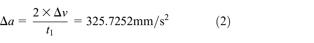
When the rope passes through the transition region, the equivalent winding radius changes, leading to the variation of hoisting velocity and acceleration. Take the transition region 2–3 shown in Figure 2(a) for example, the length of the curve l1, which is composed of two tangent lines and one circular arc, values 22.9636 mm, and the arc length l2 which corresponds to β1 is 17.8023 mm. Thus, the variation of hoisting velocity and acceleration can be calculated as

According to the three-stage winding scheme and the calculation results of the winding drum, the hoisting velocity and acceleration can be obtained as shown in Figure 3.

Hoisting parameters: (a) hoisting velocity and (b) hoisting acceleration.
It can be seen from Figure 3 that the hoisting velocity and acceleration change periodically during the uniform winding stage. When passing through the transition zone, the change of winding radius will bring sudden changes in velocity and acceleration of 28.9928 mm/s and 325.7252 mm/s2. When passing through the straight-line zone, the velocity and acceleration will not change.
Model establishment in ADAMS
Modeling of hoisting rope
In mine hoists, the length of catenary is relatively small compared to the length of the vertical hoisting rope, so the catenary can be viewed as an additional rope connected to the hoisting rope along with the direction of the hoisting velocity, as shown in Figure 1. In ADAMS, the structure of head sheave and drum can be overlooked for the following two reasons. (1) On the one hand, the winding behavior between the drum and the steel wire rope is hard to establish precisely, and the contact force algorithm is extremely complex which will lead to convergence difficulties and greatly reduce the solution efficiency. (2) On the other hand, the main function of the head sheave is to service as the guide device for rope, at the same time, the contact force between the rope and head shave will cause the same problems in (1). Hence, in this section, the model of longitudinal vibration will mainly focus on the establishment of hoisting rope and steel guide system.
The first and foremost thing is to establish the hoisting rope accurately and rapidly by using the bushing method. The hoisting rope was viewed as a continuity consists of multi-discrete cylinders, the virtual prototype model of the rope was built by copying, moving discrete bodies, and adding bushing force between each two bodies according to secondary development instruction. The stiffness and damping coefficients which can reflect the physical and vibration behavior of the rope should be calculated to effectively simulate the characteristics of the steel wire rope. The stiffness coefficients 18 are obtained according to Table 1. The value of damping coefficient is generally between 1 and 10 Ns/mm, take 5 Ns/mm.
Formulas and results of stiffness coefficients.

In Table 1, E is the elastic modulus of steel wire rope and values 4.10 × 10⁴ MPa; A is the cross-sectional area of steel wire rope; l is the actual length of discrete steel wire rope, l = 10 mm; G is the shear modulus of steel wire rope, G = 1.64 × 10⁴ MPa; D is the diameter of the discrete cylinder, D = 2 mm. According to the above steps and parameters, the hoisting rope composed of 1860 discrete cylinders is established in Figure 4.

Partial model of hoisting rope.
In order to obtain the longitudinal response of the hoisting system subject to drum winding excitation, the calculated drum periodic speed excitation is imported into ADAMS in the form of spline data with one column of time and the other column of corresponding velocity. Add a moving motion at one end of the rope along with the axial direction, add cubspl(time,0 spline_1,0) as the velocity input of the motion. Set the simulation duration as 6.8 s and step size as 0.01.
Modeling of steel guide system
The steel guide system consists of steel guide and guide rollers. The guide rollers are installed on the upper and lower side of the conveyance. When the drum is winding, the lifting conveyance is pulled by hoisting rope and the guide roller rolls up and down along the steel guide realizing the guiding function.
Firstly, the model of steel guide system along with the lifting conveyance is completed in SolidWorks, as shown in Figure 5. The guide roller is composed of roller, rocker arm, spring and base, et al. Now there are some researches about structural innovations of guide roller and optimization of its stiffness and damping coefficients in order to improve the reliability and durability of guide roller. This section focuses on the vibration response of the hoisting system under disturbance excitations, therefore, the spring of the guide roller was regarded as a linear spring with the stiffness coefficient of 2 N/mm and the damping coefficient of 1 Ns/mm. When the guide roller encounters interface misalignment of steel guide, it receives the force of inward extrusion which transmits to the spring through rocker arm. The spring is compressed and drives the rocker arm to deflect to the inside. At the same time, the outer ring of the roller can also play the effect of cushioning and vibration reduction so that the guide roller can pass through the dislocation.

Steel guide system.
Then, the material and constrain relationship of all the parts should be added after the model has been imported into ADAMS as x_t file. Generally, the outer ring material of the roller is polyurethane. According to relevant literature, 19 the density of polyurethane is 1.0 × 10⁶ kg/mm3, the elastic modulus is 25 N/mm2, and the Poisson’s ratio is 0.49. The materials of other parts are steel, with an density of 7.8 × 10⁶ kg/mm3, an elastic modulus of 2.07 × 10⁵ N/mm2, and a Poisson’s ratio of 0.29.
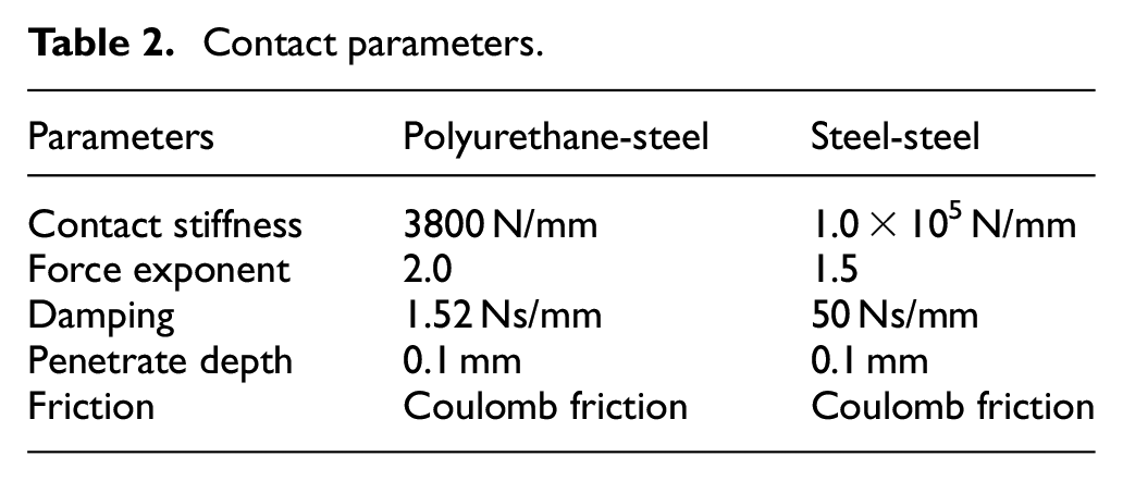
The guide rollers are fixed on the conveyance, and the corresponding constrains are set inside the guide roller. The conveyance is fixed with the first part of hoisting rope, and a moving constraint is put on the other end of the rope along with the lifting direction. Afterwards, contact forces should be added between every two connecting parts. In ADAMS, the contact force is generally expressed by impact function, 20 the normal contact force formula during collision:

where K is Hertz contact stiffness,
Contact parameters.
There are usually three kinds of steel guide excitation: impact excitation, harmonic excitation, and random excitation. Harmonic and random excitation are mainly caused by bending, tilt, and overall random irregularity of steel guide which have less influence of the hoisting system compared to impact excitation which is caused by local crowning and interface misalignment. This section takes interface misalignment fault as the main excitation source. Suppose the size of interface misalignment is 5 mm on one side of steel guide.
Suppose the interface misalignment fault occurs on one side of the steel guide during uniform lifting process and the displacement in horizontal direction is 5 mm, move one steel guide along the horizontal direction for 5 mm, and set the velocity input as three-stage scheme without periodical winding excitation.
Experimental validation
Figure 6 shows the test rig of the lifting system. The steel wire rope with a diameter of 2 mm and a tensile stiffness of 12,881 N/m was wound on the cylinder drum, and then connected to the lifting weight of 1.49 kg though a small pulley. One small cylinder object with diameter of 4.5 mm was wrapped on the drum. A steel wire rope with a diameter of 5 mm was bound around one side of the steel guide to simulate the interface misalignment fault. The dynamic force of the hoisting system can be obtained by the tension sensor which was connected between the end of the rope and the lifting weight.

Test rig.
Figure 7 shows the dynamic force at the conveyance end of the rope, in which the red line represents the ADAMS simulation results and the blue line represents the experimental results. It can be seen from the figure that that trend of two curves is basically the same. At the beginning, the dynamic force from simulation and experiment fluctuates with the sudden change of lifting speed. Then, it changes periodically corresponding to the periodic changes of the velocity and acceleration caused by drum winding. Moreover, the values of the peaks and troughs of the wave in each circle are basically stable.

Dynamic force at the conveyance end of the rope from simulation and experiment under period excitation: (a) dynamic force at the conveyance end of the rope and (b) enlarged view.
Figure 8 demonstrates the dynamic force under interface misalignment of steel guide, the red line represents the simulation results, and the blue line represents the experimental results. The dynamic force fluctuates rapidly at the beginning and the end short period of lifting process. In case of interface misalignment fault, the rope tension fluctuates within a certain range due to the impact acceleration of the guide roller. While, the attenuation speed of the tension from ADAMS simulation is slightly faster than that in the experiment probably because of the inconsistency of the roller spring coefficients in simulation model and test. The slight difference between the measured and simulation results in dynamic force is mainly because that different simulation algorithms in ADAMS will affect simulation result, and random disturbance excitations of the experimental platform can be hard to eliminate. On the whole, the ADAMS simulation results and the experimental results are relatively consistent in Figures 7 and 8 which prove the accuracy of the established hoisting model under two types of disturbance excitation.

Dynamic force at the conveyance end of the rope from simulation and experiment under interface misalignment of steel guide: (a) dynamic force at the conveyance end of the rope and (b) enlarged view.
Vibration suppression
In order to reduce the longitudinal vibration of the lifting system caused by drum winding and interface misalignment of the steel guide, a vibration reduction device consisting of four series spring-dampers was installed between the steel wire rope and the conveyance based on virtual prototype, as shown in Figure 9. The upper end of the spring-damper device is connected to the hoisting rope, and the lower end is connected with the conveyance through a short rope. Two translational joints along the lifting direction are respectively set at both end of the spring-damper so that the degrees of freedom in other directions of the device can be limited. Set the stiffness coefficient as 8 N/mm and the damping coefficient as 0.5 Ns/mm. when the tension of hoisting rope changes due to external excitation, the spring-damper system will play the role of buffering and absorbing the vibration, thus, the vibration of the conveyance can be reduced and the stability of the whole lifting system can be improved.

Schematic view of the hoisting system with a spring damper device.
The comparison diagrams of the vibration acceleration of the lifting conveyance subject to different disturbances were obtained by ADAMS in Figures 10 to 12. Figure 10 shows the acceleration response of the conveyance subject to drum winding. It can be seen from Figure 10 that the acceleration of the conveyance presents the characteristics of periodic vibration, and the vibration period is about 0.64 s. By applying the vibration reduction device, the acceleration of the conveyance can be greatly reduced. During one oscillation period, the peak value of acceleration of the conveyance has been decreased from 2410 to 1228 mm/s2 by 49.05%, and the absolute value of trough acceleration has been decreased from 2800 to 1233 mm/s2 by 55.96%. In addition, the vibration can be attenuated quickly with spring-dampers and the vibration frequency has been significantly reduced.

Comparison of acceleration of the conveyance under period excitation: (a) comparison of acceleration of the conveyance and (b) enlarged view.

Comparison of acceleration of the conveyance under interface misalignment fault: (a) comparison of acceleration of the conveyance and (b) enlarged view.

Comparison of acceleration of the conveyance under two disturbance excitations: (a) comparison of acceleration of the conveyance and (b) enlarged view.
The comparison diagram of conveyance acceleration response subject to interface misalignment fault was presented in Figure 11. In case of one-side steel guide failure, the acceleration of the conveyance has been suddenly increased from 0 to 4866 mm/s2, and then fluctuates periodically. The instantaneous sudden acceleration of the conveyance has been declined from 4866 to 3708 mm/s2 by 23.80%
Figure 12 demonstrates the comparison of acceleration of the conveyance under period excitation and interface misalignment fault. In the absence of vibration reduction device, the conveyance vibrates continuously and periodically under drum excitation, and the acceleration fluctuation of the conveyance does not exceed 4000 mm/s2. When the guide roller encounters the interface misalignment fault, the maximum acceleration value of the conveyance has been increased to 8428 mm/s2 which is 42.26% higher than that in the case of only interface misalignment fault in Figure 12. However, the influence time of the excitation generated by the interface misalignment fault is relatively short and the vibration gradually attenuates in a fluctuation cycle. By using the vibration reduction device, the maximum vibration acceleration of the conveyance has been reduced from 8428 to 5459 mm/s2 by 35.23%.
It can be concluded that the vibration reduction device can play a good role in suppressing the vibration amplitude and frequency in the lifting systems, both in the case of single excitation and coupling excitation, which provides a certain guiding significance for the vibration reduction in the mine hoisting systems.
Conclusion
In this paper, the longitudinal vibration characteristics of the mine hoisting system subject to two disturbance excitations were investigated. Firstly, the change of equivalent winding radius was described from the derived model of a hoisting experimental platform, and the periodic velocity and acceleration excitations were calculated. Secondly, the coupled virtual prototype model of the steel guide and rope system was completed in ADAMS, and the excited longitudinal dynamic responses at the end of the rope were obtained. Finally, a vibration reduction device consisting of four series spring-dampers was proposed to be installed between the conveyance and the end of the rope. The main conclusions can be drawn as follows:
The interface misalignment of steel guides will cause impact vibration response of the steel wire rope, and the coupling excitations including drum winding and the interface misalignment of steel guides can induce more intense impact vibration. The simulation model in ADAMS was verified by comparing to the dynamic force measured from the experiment.
The proposed spring-damper device plays a good role in reducing the acceleration of the conveyance subject to both excitations. Both the amplitude and the frequency of the longitudinal vibration have been effectively reduced. The impact acceleration in the case of interface misalignment and periodic excitation has been reduced by 23.80% and 49.05%, respectively. In future, some semi-active and active control methods can be integrated to achieve better damping effects.
The paper can provide good theoretical basis for the vibration reduction and optimization of the lifting system.
Footnotes
Handling Editor: Chenhui Liang
Declaration of conflicting interests
The author(s) declared no potential conflicts of interest with respect to the research, authorship, and/or publication of this article.
Funding
The author(s) disclosed receipt of the following financial support for the research, authorship, and/or publication of this article: The authors gratefully acknowledge the support of National Natural Science Foundation of China (Grant Nos. 51805273, 51975569), and the support of Qing Lan Project of Jiangsu Province and the Priority Academic Program Development of Jiangsu Higher Education Institutions.