
Abstract
Compression stockings are the most common treatment for lymphatic and venous diseases of the lower limbs. Their mechanical behaviour is governed by a specific weft-knitted design, in which an inlay yarn is inserted into each course of the loop structure, acting as reinforcement. Numerous studies have modelled the knitted fabric to predict its tensile behaviour. Specifically, numerical finite element models are increasingly used to evaluate the performance of compression garments. However, they do not represent the local fabric structure and often rely on homogenised approximations. This study proposes a hybrid model to predict the circumferential tensile response of compression stockings. The model incorporates the elastic properties of the loop structure and inlay yarn, as well as the local distribution of inlay yarn, which plays a key role in fabric circumferential stiffness. A unit cell was used to model the weft-knitted fabric at a mesoscopic level. 3D-shell elements and connectors were combined in the unit cell to model the mechanical behaviour of the loop structure and the inlay yarn, respectively. Mechanical and structural parameters were identified from experimental data. The model was applied to the two main zones of a medical compression stocking, ankle and calf. The results were validated through comparison with experimental tensile data, showing strong agreement. This approach is considered suitable for future finite element models aimed at simulating pressure distribution in medical compression fabrics.
Introduction
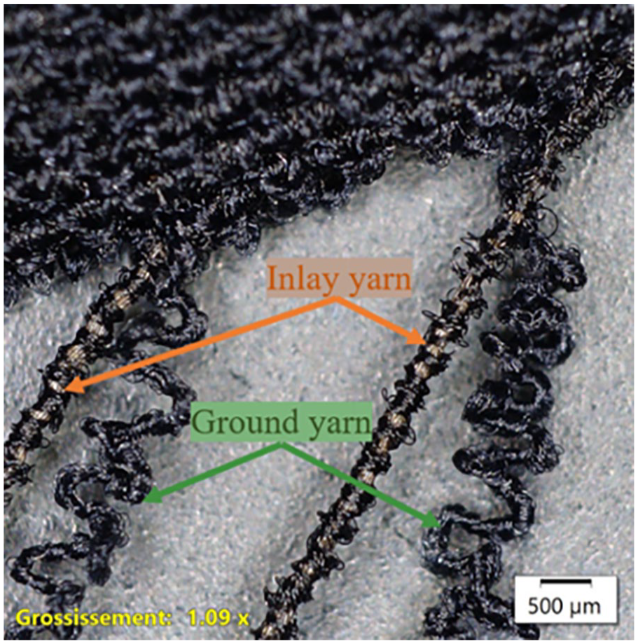
Lymphoedema and chronic venous insufficiency are among the most common diseases affecting the lower limbs of adults.1,2 Compression therapy is widely accepted as the main method of prevention and treatment. In the case of lower limb disorders, medical compression stockings (MCS) are typically used.1–4 Their goal is to restore the function of the calf muscle pump by applying external pressure, which reduces the diameter of blood and lymphatic vessels and improves fluid drainage.5,6 Compression stockings must combine several properties, including therapeutic compression, anatomical adaptability and comfort. This is achieved using a specific weft-knitted structure that combines two types of elastane-based yarns: the ground yarn, which forms the loop structure in the wale (longitudinal) direction, and provides deformability and comfort and the inlay yarn, which is inserted in each course of the loop structure without forming loops, and reinforces the fabric. 7 This results in a 1 × 1 inlaid weft-knitted structure, as showed in Figure 1.

1 × 1 inlaid weft-knitted structure of medical compression stocking.
Because the inlay yarn is inserted in every course of the structure, the course density, expressed in courses per millimeter (
To achieve the desired compression, the garment is designed with a smaller circumference than the body. The tensions arising from stretching the garment when placed over the limb, are transferred as pressure to the surface and onto the internal vessels. This phenomenon is explained by Laplace’s law, and has been widely studied in the field of compression therapy.1,8–11
Several approaches have been developed to evaluate the pressure exerted by compression fabrics. These methods are essential for characterising garment performance and ensuring therapeutic efficacy. They include direct measurement techniques, analytical models and numerical simulations.
Direct methods typically rely on pressure sensors placed between the garment and the body, or embedded in physical mannequins. For example, Li et al. developed a custom-fabricated leg mannequin with embedded transducers to study pressure variation across compression zones. 12 However, pressure sensors provide only localised measurements, which limits their ability to capture the full pressure distribution over the body surface. Moreover, the presence of the sensor itself, even when thin (e.g. Picopress), can disturb the actual interface pressure by altering the local curvature of the limb. In the case of smart mannequins, their simplified geometry, typically cylindrical or conical, does not replicate the complex anatomical shape of the human limb.10,11,13,14
Analytical methods use mechanical testing in combination with equations such as Laplace’s law. This law relates interface pressure to fabric circumferential tension and limb radius, assuming a cylindrical geometry. Standard protocols such as NF G30-102 (AFNOR, 1986) provide guidelines for the classification and measurement of compression performance. 15 However, this formulation assumes uniform tension and regular cross-sectional shape, which limits its accuracy when working with complex anatomical shapes. To address these limitations, various refinements of Laplace’s law have been proposed. Teyeme et al. and Siddique et al. developed updated models that incorporate fabric stretch, thickness and material constants, resulting in improved agreement with experimental data.16,17
Finite element (FE) simulations have emerged as a powerful tool to overcome the limitations of experimental and analytical methods. These models can account for detailed limb geometry, fabric properties and garment-body interaction. Ye et al. proposed a 3D FE model to simulate the transmission of pressure from elastic stockings to soft tissues. 18 Ghorbani et al. modelled the stocking using solid continuum elements (C3D8R), modelling the fabric as a homogenised surface to predict global mechanical response. 19 Similarly, Lu et al. used a highly anatomical calf model to predict the fabric–body interaction. 10 Complementary anatomical studies, such as that of Kyzymchuk et al., employed 3D scanning and garment simulation to evaluate the geometric deformation of the limb under compression. 20 While these approaches enhance realism, most existing models do not model the internal architecture of the fabric, particularly the inlay yarn distribution. This highlights the need for structurally resolved models that capture the mesoscopic mechanical behaviour of compression fabrics.
The mechanical behaviour of knitted compression fabrics directly influences the pressure profile delivered by medical compression stockings (MCS). Several modelling strategies have been proposed to represent their behaviour, particularly for integration into finite element (FE) simulations of the garment–body interaction.
The most common approach uses homogenised continuum models, which represent the fabric as an orthotropic membrane or shell, with properties identified from tensile tests. For example, Chen et al. and Zhang et al. represent the fabric as an orthotropic surface characterised from experimental data, enabling efficient simulation of the stocking–limb system.21,22 However, these models neglect the meso-structure of the knitted fabric, and do not distinguish the mechanical roles of the loop structure (ground yarn) and the inlay yarn.
Other studies have explored mesoscopic models based on unit cells, aiming to reflect the geometry and deformation of the looped structure more realistically. Ghorbani et al. developed 3D models of rib weft-knitted fabrics with inlay yarns, using solid continuum elements (C3D8R) in Abaqus.19,23 Their models treat the fabric as a single continuous medium and incorporate viscoelastic behaviour via Prony series. While they show good agreement with experimental tensile tests, they do not differentiate the structural contributions of the loop and inlay yarns and the inlay distribution is fixed.
Analytical models have also been proposed to estimate the tensile response of knitted fabrics, often based on idealised loop geometries and mechanical properties of yarns. For instance, de Araujo et al., Ye et al. and Fong et al. modelled knitted loop deformation using simplified geometric assumptions.24–26 These approaches are valuable for understanding local mechanics, but their applicability in full-scale simulations is limited by geometric idealisations and computational constraints.
More recently, Kowalski et al. proposed a computer-assisted method for the design of compression garments based on multilayer fabric representations and optimisation of pattern geometry. 27 However, their approach still models the textile as a continuous elastic layer, without explicit representation of the internal fabric structure.
While these approaches contribute valuable insights into the behaviour of compression fabrics, several key limitations remain. Homogenised models lack structural detail and do not differentiate between the mechanical behaviour of the loop structure and the inlay yarn. While mesoscopic unit cell models provide a more accurate geometric description, they often treat all yarns as part of a continuous medium and do not reflect their distinct mechanical roles. Analytical models, though useful for loop-level understanding, generally require simplifications that restrict their integration into full-scale FE simulations. Moreover, a critical structural parameter such as the inlay yarn distribution, reflected by the number of courses per millimetre (
These results highlight the limitations of simplified or homogenised modelling approaches and emphasise the need for models capable of representing the mesoscopic scale of the knitted structure and their contribution to the overall mechanical response of compression fabrics, while remaining compatible with fabric-body FE simulations. To address these limitations, this study proposes a hybrid mesoscopic model that explicitly defines the two main components of weft-knitted compression fabrics: the loop structure is modelled using 3D-shell elements, capturing its low stiffness and deformability. The inlay yarn is represented with discrete connectors, which account for its dominant role in controlling circumferential deformation. The model is based on a representative unit cell, with parameters derived from experimental measurements of fabric geometry and tensile behaviour. Unlike most existing models, this approach integrates the inlay yarn distribution as a zone-specific structural input, allowing the simulation to reflect the variation in circumferential stiffness along the length of a gradual-compression stocking.
Validation against tensile tests confirms the model’s ability to reproduce the circumferential mechanical response of the fabric, for different compression zones and fabric configurations. Because of the strong agreement between simulated and experimental data, the model is considered suitable for integration into finite element simulations of the stocking–limb interaction, providing a novel approach for predicting pressure distribution in compression therapy.
Materials and methods
Materials
This study focused on a medical compression stocking (MCS) manufactured by Sigvaris France. The product analysed was a women’s semi-transparent stocking, size M, designed to apply graduated compression across three zones, ankle, calf and thigh, with a decreasing pressure profile.
The fabric has an 1 × 1 inlaid weft-knitted structure, knitted from two types of polyamide double-covered elastane yarns. The ground yarn (22/22/22 dtex) formed the loop structure in the wale (longitudinal) direction, while the inlay yarn (310/22/22 dtex) was laid into each course without forming loops, reinforcing the fabric in the circumferential direction.
The objective of this study is to develop a mechanical model capable of predicting the tensile response of the inlaid weft-knitted fabric. The approach focuses on quantifying the individual contributions of the ground and inlay yarns, as well as the influence of structural parameters, particularly the number of courses per centimetre (
Among the different structural and manufacturing parameters,
Fabric samples were independently knitted for each zone using the same knitting parameters as the commercial product. Two configurations were produced: a standard inlaid weft-knitted fabric (IF), and a weft-knitted fabric, with the same ground yarn and loop structure, without inlay yarn (WF). All fabric samples, presented in Figure 2, underwent the complete industrial process, including knitting, dyeing and heat-setting, to ensure that their mechanical and dimensional properties reflect those of the finished medical compression stocking. The coloured reference lines knitted into the fabric facilitate both the correct positioning of the samples during tensile testing and the structural analysis. The distance between lines was defined as

Weft-knitted fabric samples for each compression zone, with inlay yarn (IF) and without inlay yarn (WF).
Relaxed and maximum circumferential dimensions for a size M medical compression stocking.

Each compression zone is designed to fit a specific range of limb circumferences, according to manufacturer specifications. When worn, the fabric stretches until its perimeter matches that of the limb. Thus, the deformed perimeter of the fabric corresponds to the circumference of the patient’s leg in each compression zone. The circumferential strain, expressed in equation (1), represents the relative deformation of the fabric when stretched around the limb, where P0 is the initial perimeter of the fabric and

In this study, the maximum perimeter (
The relaxed and maximum perimeters of the fabric samples for each zone are presented in Table 1. The difference between the relaxed and maximum perimeters is lowest in the ankle zone, indicating the smallest deformation range. This observation aligns with the expected highest circumferential stiffness in the ankle region, which will be further examined in the following sections. Also, the comparison between the two fabric configurations (IF and WF) reveals a clear difference in perimeter variation between zones. In the weft-knitted fabric with inlay yarn (IF), the relaxed perimeters differ significantly between the ankle and calf, reflecting the design strategy for applying graduated compression. This is achieved by adjusting the inlay yarn insertion in the course direction, allowing precise control of the fabric circumference for each zone. In contrast, in the weft-knitted fabric without inlay yarn (WF), the relaxed perimeters almost do not vary between zones. This confirms that, in the absence of inlay yarns, the structural design loses its ability to adapt to the desired pressure profile. The inlay yarn is therefore essential for defining the relaxed shape of the garment and achieving compression control through deformation.
Inlay yarn samples used for tensile testing were extracted by de-knitting from finished products that had also undergone the full manufacturing process, as shown in Figure 3. This ensured that the tested yarns reflect any changes in mechanical behaviour resulting from thermal and chemical treatments applied during production.
De-knitting process to obtain inlay yarn samples from the inlaid weft-knitted fabric.
Assessment of structural and mechanical properties
Structural characterisation
The course density (
The course density was calculated according to equation (2), where

Fabric tensile testing
The tensile behaviour along the circumferential direction of the knitted fabrics was evaluated using uniaxial tensile testing, following the standard NF G30-102-B.
15
The tests were performed on the cylindrical samples described in Section 2.1, corresponding to the two main compression zones of the stocking: ankle and calf. Two fabric configurations were tested: the weft-knitted fabric with inlay yarn (IF) and the weft-knitted fabric without inlay yarn (WF), both knitted with the same ground yarn and loop structure. Prior to testing, each sample was placed on a standard Hohenstein wooden leg at its corresponding compression zone. The fabric over the leg was massaged for 30 s and allowed to rest for 2 h, following the standard protocol. After this time, the relaxed circumference of the sample was measured and considered as the initial perimeter (
Initial dimensions of the weft-knitted fabrics, measured after placement on wooden leg and considered for the tensile test.

Tensile tests were performed using a Zwick Z005 universal testing machine, equipped with a 100 N XP-force load cell (2 mV/V sensitivity). Samples were clamped along their longitudinal axis, with a constant spacing between reference lines of 22.5 mm (Figure 4(a)). For the ankle samples, parallelogram-shaped stabilisers were used at both ends to prevent longitudinal displacement during loading (Figure 4(b)). This was not necessary for the calf, where edge effects were negligible. This fixation method enabled a non-destructive tensile test along the full circumference of the sample, avoiding localised necking and ensuring bidirectional force distribution. This setup also ensured that the measured response accurately reflects the mechanical behaviour of the fabric in use.

Tensile test procedure for weft-knitted fabric samples: (a) placement of fixation pins along the longitudinal direction of the sample, (b) attachment of the sample to the testing machine, including parallelogram fixation for ankle samples and (c) example of loading–unloading cycles.
Each sample underwent two consecutive loading–unloading cycles at a constant speed of 200 mm/min (Figure 4(c)). A pretension of 0.01N was applied to all the weft-knitted samples. The effective fabric length (
Due to knitting limitations, only one specimen per compression zone was available for each fabric configuration. While a single sample was tested per case, the results were found to be consistent with expected mechanical performance and were validated by the manufacturer, confirming their representativeness under the defined conditions.
During the tensile test, the force was recorded as a function of the imposed displacement. The corresponding circumferential strain values were calculated, according to equation (1). The resulting force–strain curves were used to evaluate the circumferential tensile response of the fabric. The results of weft-knitted fabrics without inlay yarn (WF) was used to determine the elastic modulus (
Yarn tensile testing
The tensile behaviour of the inlay yarns was characterised through single-yarn tensile testing. Yarns were extracted (de-knitted) from finished medical compression stockings that had undergone the full industrial process, including knitting, dyeing, heat-setting and mechanical stabilisation. This ensured that the measured mechanical properties reflected the yarn’s actual condition in the final product.
Tests were carried out using a Statimat ME+ tensile tester (serial no. 36723) equipped with a 32 N load cell (serial no. 17309147). The procedure followed the manufacturer’s internal protocol for covered elastic yarns. The testing conditions included a pretension of 0.01 cN/tex, and crosshead speed of 600 mm/min.
The yarn strain, calculated with equation (3), represents the inlay yarn relative deformation, where
A total of five inlay yarn samples were tested, and the average tensile response was determined. Variability between samples was low, confirming the reliability of the experimental data. The average force-strain curve was used to define the tensile response of the inlay yarn in in-use conditions, and to identify the stiffness parameter (k) of the connector representing its mechanical contribution in the hybrid model.

No individual tensile tests were performed on the ground yarns creating the loop structure. Instead, its mechanical behaviour was obtained from the tensile response of the weft-knitted fabrics without inlay yarns (WF), as described in Section 2.2.2.
Hybrid model of the medical compression stocking
A hybrid mechanical model was developed to predict the circumferential tensile response of the inlaid weft-knitted fabric used in medical compression stockings. The model enables a transition between the macroscopic fabric level and the mesoscopic yarn level. The local structure of the knitted fabric was represented by unit cells with hybrid elastic behaviour. As shown in Figure 5, each unit cell combines continuous and discrete elements to represent the loop structure and inlay yarns, respectively. The global mechanical response of the fabric was obtained by superposition of the unit cells.

Schematic representation of the hybrid model of a medical compression stocking.
Mechanical parameters
The mechanical parameters allowed to model the tensile behaviour of both the loop structure and inlay yarn in the medical compression stocking.
The loop structure was modelled as a homogeneous and isotropic material, represented by 3D-shell elements. Its elastic behaviour was defined by the Young’s modulus (
The inlay yarn was modelled using discrete elements (connector) with spring behaviour. The tensile response of the spring was defined by its stiffness (
Dimensional parameters
The dimensional parameters allowed to model the anisotropy of the weft-knitted fabric, and the inlay yarn distribution, which are key parameters influencing the tensile response of medical compression stockings.
The unit cell height (

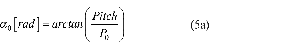
The inlay yarn describes a helical path along the longitudinal direction of the fabric. The inclination of the inlay yarn was modelled by assigning an inclination angle (

The final representation of the fabric was obtained by superposition of unit cells along both longitudinal and circumferential directions. The number of unit cells along the longitudinal direction (


Prediction of the tensile response of weft-knitted fabrics with the hybrid model
The hybrid model was applied to predict the circumferential tensile response of the weft-knitted fabric used in medical compression stockings. This approach allowed for a detailed analysis of the mechanical contributions of both the loop structure and the inlay yarns.
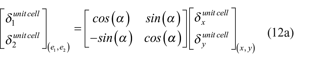
During tensile testing, the fabric was stretched along the circumferential direction. To model this, the fabric’s orthonormal coordinate system (

Strain decomposition at fabric and unit cell level for the hybrid model of a medical compression stocking.
As mentioned in Section 2.3.2, an inclination was imposed to the unit cell to model the helicoidal path described by the inlay yarn the fabric. The unit cell’s local coordinate system (


The model was adjusted for each compression zone using the initial perimeter (
By computing the strain and force at the scale of the unit cell, the model predicts the overall tensile behaviour of the fabric, reflecting the contribution of both the loop structure and inlay yarns. The strain–force analysis was performed only in the circumferential direction (
The circumferential elongation of the fabric (


The inclination angle of the unit cell (


The loop structure was modelled by 3D shell elements with isotropic linear elastic behaviour. According to Hooke’s law for isotropic materials, the internal force (
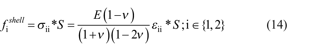

At the unit cell level, only the 3D-shell contributed to the load in the wale direction (


A second rotation matrix was used to convert these loads into the fabric coordinate system, allowing the calculation of the circumferential force per unit cell (


Analytical method for parameter identification
The analytical formulation described in Section 2.4 was used to identify the mechanical parameters required for the hybrid model. These parameters include the Young’s modulus (
First, an inverse identification approach was applied for the 3D-shell parameters. The circumferential tensile response of the weft-knitted fabric without inlay yarn (WF) was simulated using the hybrid model, including only the shell elements. This process was performed without the inlay yarn, to isolate the mechanical behaviour of the loop structure. The values of
Then, the mechanical response of the inlay yarn was evaluated from tensile tests results on de-knitted yarns (Section 2.2.3). A scaling was carried out to obtain the connector stiffness (
Validation of the hybrid model
The hybrid model was validated by comparing the predicted tensile response with the experimental data of the weft-knitted fabrics under circumferential loading. Two fabric configurations were analysed: weft-knitted fabrics without inlay yarn (WF), and inlaid weft-knitted fabrics (IF).
Simulations were performed using the identified mechanical parameters. For each compression zone, the model was adjusted with the corresponding initial perimeter (
In the W configuration, the fabric was modelled using only 3D shell elements representing the loop structure. In the S configuration, the fabric was modelled using both shell and connector elements. A correction factor was applied to the connector stiffness to account for the difference between the tensile response of free yarns and their behaviour when integrated into the fabric.
The circumferential deformation of the weft-knitted fabrics was simulated for ankle and calf, and the tensile response was predicted. The accuracy of the model was quantitatively assessed using the mean absolute error (MAE) between the predicted and experimental curves.
Results and discussion
Experimental characterisation
Inlay yarn distribution
The main structural parameter analysed was the course density (
Table 3 presents the
Calculated values of courses per millimetre (CPM) for different compression zones in relaxed state (R) and tensile testing (T).

Tensile response of knitted fabrics
The circumferential tensile response of the weft-knitted fabrics was evaluated for both configurations: with inlay yarn (IF) and without inlay yarn (WF). Figure 7 presents the corresponding force–strain curves for the ankle and calf zones. The strain values were calculated using equation (1), which defines the circumferential strain as the ratio between the variation in perimeter and the initial perimeter.

Experimental tensile response of knitted fabric under circumferential deformation: (IF) weft-knitted fabric with inlay yarn, (WF) weft-knitted fabric without inlay yarn.
In the IF configuration, the registered tensile force for a given strain was significantly higher than in the WF configuration for both zones. This confirms that the inlay yarn is the main contributor to the fabric’s circumferential stiffness. Moreover, the tensile response of the IF fabrics is consistent with the structural data, as zones with higher course density, such as the ankle, exhibit higher tensile forces for a given circumferential strain. This confirms the role of the inlay yarn distribution in modulating the mechanical response of the fabric.
In contrast, the WF configuration, which has only the loop structure, showed a much more compliant behaviour, with tensile forces approximately 10 times lower than those measured in the fabrics with inlay yarn (IF). As observed in the study, the loop structure contributes only about 10% of the total circumferential stiffness, highlighting the mechanical importance of the inlay yarns in the compression performance. The small variation observed in the tensile response of the WF configuration between zones suggests that the loop structure behaves consistently throughout the stocking. This allowed for a single set of mechanical parameters to be defined for the 3D-shell elements representing the loop structure in the hybrid model.
Tensile response of inlay yarn
The tensile response of the inlay yarn was evaluated through single-yarn tensile tests. The strain values were calculated using equation (3). The force–strain curve obtained from the third cycle is shown in Figure 8. The curve presents a typical non-linear behaviour, with an initial linear segment followed by progressive stiffening. The linear region is considered in a strain range between 0 and 2 mm/mm. This response is characteristic of covered yarns, composed of a spandex core and polyamide coverings as previously introduced by Ye et al. and Bruniaux et al.28,29

Experimental tensile response of the inlay yarn from the third loading cycle.
The maximum strain within the linear region exceeds the maximum strain observed in the S fabric samples during tensile testing. This confirms that, under typical deformation levels, the inlay yarn responds within its linear elastic range. Therefore, the linear section of the curve was used to define the stiffness (k) of the connector, representing the inlay yarn’s mechanical contribution.
Parameter identification
The parameters used in the hybrid model were identified from the experimental results described in Sections 3.1.1-3.
The hybrid model was applied to simulate the tensile response of the weft-knitted fabric without inlay yarn (WF). The mechanical parameters of the 3D-shell, Young’s modulus (
To determine the optimal parameter set, a sensitivity analysis was carried out. The model’s accuracy was assessed using the mean absolute error (MAE), expressed in Newtons, calculated between the model’s predictions and the experimental tensile curves. The total error was calculated as the sum of the MAE values for both compression zones (ankle and calf), in order to evaluate the global effect of each parameter combination. Multiple combinations were tested, and the results are summarised in Tables 4 and 5.
Mean absolute error (MAE) between model prediction and experimental data for WF, for different Young’s modulus of 3D-shell and ν= 0.1.

Mean absolute error (MAE) between model prediction and experimental data for WF, for different Poisson’s coefficient of 3D-shell and

The analysis showed that Young’s modulus had a significant effect on the model’s performance, while the Poisson’s ratio had little influence. The pair
Identified mechanical parameters for the hybrid mechanical model.

The stiffness (
Validation of the hybrid model
The hybrid model was validated by comparing the simulated tensile response with experimental results for two configurations: the fabric without inlay yarn (WF), and the inlaid weft-knitted fabric (IF). Both ankle and calf zones were evaluated, using the same mechanical parameters (Table 6) and zone-specific course density values from the tensile test (
First, the tensile response of the W fabric was simulated using shell elements only, without inlay yarn connectors. The same mechanical properties were applied for both zones, while the
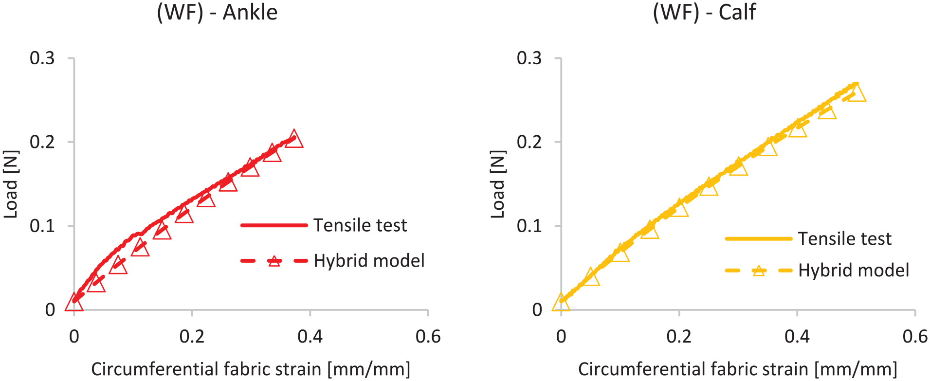
Comparison between simulated and experimental tensile response of weft-knitted fabric without inlay yarn (WF).
Then, the complete fabric response (IF) was simulated by integrating both shell and connector elements. The same mechanical parameters were used for all zones, and the

Comparison between simulated and experimental tensile response of inlaid weft-knitted fabric (IF).
These results confirm that the hybrid model reliably predicts the mechanical tensile response of inlaid weft-knitted fabrics. It accounts for the contribution of each yarn component and the local structural variations driven by course density. The model is therefore suitable for further integration into finite element simulations of compression stockings.
Conclusion
This study presented a hybrid mechanical model to predict the circumferential tensile response of weft-knitted fabrics used in medical compression stockings. The model was based on a mesoscopic representation of the fabric through unit cells that combine shell elements for the loop structure and connector elements for the inlay yarn. Mechanical parameters were identified experimentally and kept constant across zones, while structural parameters such as course density (CPM) and initial perimeter were varied to reflect the gradual compression design of the stocking.
The hybrid model successfully predicted the tensile response of fabrics with and without inlay yarns across different compression zones. The model accurately reproduced the tensile behaviour of fabrics with and without inlay yarns in different compression zones. It represented the mechanical contribution of the inlay yarn, which increases with course density. The results confirmed that the loop structure plays a secondary role in the fabric’s circumferential tensile strength compared to the inlay yarn. Its performance was validated by comparison with experimental data and evaluated using the mean absolute error (MAE).
The selected modelling elements, shells for the loop structure and connectors for the inlay yarn, can be directly used in finite element simulations. This makes the model suitable for integration into simulations of compression garments. These simulations can help predict the pressure applied to the limb, based on the fabric’s circumferential deformation.
The model also allows separate control of the mechanical behaviour of each yarn. This helps evaluate how each yarn affects the overall response of the fabric. As a result, the model can be used to test the effect of changing yarns or modifying the fabric structure when designing new compression garments.
Future work may include implementation into 3D limb models to simulate the placement of the compression fabric and predict localised pressure fields.
Footnotes
Acknowledgements
The authors would like to express their gratitude to the company Sigvaris (Saint Etienne, France) for manufacturing and providing all the knitted fabrics and mechanical equipment used in the present study.
Funding
The author(s) disclosed receipt of the following financial support for the research, authorship, and/or publication of this article: The authors thank BPI France for the financial support of this study as part of the SYMPHONIES – PIA project.
Declaration of conflicting interests
The author(s) declared no potential conflicts of interest with respect to the research, authorship, and/or publication of this article.