
Abstract
In order to analyse the deformation mechanism and force distribution of spacer fabrics during compression progress, it is established that the loop structural model of weft-knitted spacer fabric with spacer filaments arranged in X-shape by Rhino software in this paper, and the flat plate compression behaviour of the spacer fabrics was simulated by finite element method in Abaqus software. By combining the experimental and finite element simulation, the stress distribution and change trend on the fabric were analysed when the compression amount was 5%, 20%, 35%, 50%, 65% and 80%, to investigate the failure mode of WKSFs under flat plate compression, and to achieve the progressive damage analysis of the surface layer and spacer layer yarns in the process of compression.The simulated curves of the stress-strain were consistent with the experimental results, which indicated that the model was able to reveal the compressor mechanism of the WKSFs,and provides a basis for optimising the structural design and mechanical properties of weft-knitted spacer fabrics.
Keywords
Introduction
Weft-knitted spacer fabric (WKSF) is a highly promising three-dimensional hollow structural fabric, consisting of upper and lower surface layers and a spacer layer in the middle, the two surface layers are joined together by a spacer layer of monofilaments. 1 Conventional hollow structural materials generally suffer from the problems of easy detachment and peeling of the layers. 2 However, WKSFs can be knitted as a whole in one go, with an integrated structure between the layers, which makes up for the defects of the conventional multi-layered structural materials. 3 Due to its unique structural characteristics, WKSFs are lightweight and have strong structural designability, and have important structural application value in pressure-relief protection, and have been widely used in ergonomic protection materials and cushioning products such as shoe insoles, mattresses, and car seats. 4
The compression performance of spacer fabric directly affects the usability of their finished products, 5 in which the spacer layer is the main compression-bearing layer that bears most of the compression energy during the Slow pressure process. 6 However, due to the special three-dimensional structure of WKSF, it is difficult to analyse the compression mechanism of the fabrics because it is hard to observe the complex interactions between the two outer layers and a large number of spacer monofilaments on a microscopic level by the traditional experimental method, and therefore the introduction of the finite element method. The finite element method based on numerical simulation is an effective method to study the complex mechanical properties of textiles, 7 and this technique can solve problems involving complex shapes and boundary conditions, 8 while maintaining a high computational accuracy. The microscopic force changes of the loops of spacer fabrics when subjected to external forces can be observed in the stress cloud diagram, which helps researchers to predict the compression behaviour of spacer fabrics and to design and optimise the structure, providing a theoretical basis for the selection of compression-relieving materials with good compression properties, which is of great practical significance for the development of related products.
In order to investigate the compression deformation mechanism of spacer fabric, scholars have carried out many experimental studies and verified the experiments by finite element method to reveal the complex mechanical behaviour of fabrics during compression. Brisa et al 9 investigated the bending moment change of a single vertical spacer filament of thick WKSF by using the finite element method. Yu et al 10 used a single-cell model and a macroscopic model, respectively, to study the stress distribution during the compression of fabrics through finite element simulation to study the stress distribution during fabric compression. 11 Sun et al 12 used the finite element method to analyse the stress cloud and the stress distribution along the filaments at a compressive strain of 0.6 to explore the deformation mechanism of spacer filaments under compression. However, only simple parallel aligned monofilaments were used to simulate the spacer layer, and the spacer monofilaments were reduced to the same vertical linear elastic rods, and the simplified model could not truly reflect the unique interspersed structure of spacer layer. Hou et al 13 mapped the three-dimensional model of spacer fabrics using CT scanning technology, and a single-cell model of the spacer layer was established to study the compression deformation mechanism of WKSF, however, in the process of finite element analysis The interactions between monofilaments were not considered. Orlik J et al 14 to reduce the computational volume and simplify the computational model, homogenisation and dimensionality reduction techniques were applied to the spacer fabrics by replacing the fabrics with equivalent two-dimensional plates or shells with effective elasticity, and only the outer layers were regarded as two anisotropic planes, which were not modeled accurately enough. Liu and Hu 15 created finite element models with different constraints on the spacer filaments and the thickness of the outer layer to investigate the compressor theory of the nonlinear compression behaviour of the spacer fabrics by considering yarn interactions between all the fabric constituents and materials. Sun Y et al 16 established a multiscale finite element model for the fabrics including the instrumentation and yarn constituents, and carried out a study involving friction coefficients, Young's modulus, yarn spacing and curl height parameters to analyse the compressive stresses and strains in the fabric and its internal warp and weft yarns.
Although the research on the compression behavior of spacer fabrics based on the finite element method has been more and more in-depth so far, there is still a lack of clear and detailed theoretical analysis on the bending deformation of spacer filaments during compression as well as the change process of the force distribution. 17 Moreover, the analytical models established in the previous researches neglected the interaction between the surface layer loops and the spacer filaments, analysed the most important spacer layer structure only, and ignored the potential influence of spacer The potential effects of spacer filament interactions on the fabric compression behaviour are ignored. 18 Furthermore, most of the above studies on the compression properties of spacer fabrics are centred around the conventional spacer fabrics with I-shaped spacer filaments, 19 and there are fewer finite element analyses of X-shaped spacer fabrics. Therefore, in this paper, a WKSF with X-shaped spacer filaments was knitted, and on the basis of its spacer structure, a more perfect three-dimensional simulation structural model was constructed under the condition of retaining the surface layer of loops, and finite element simulation analyses of compression performance of WKSFs were carried out under plane loads.
By analysing the stress clouds corresponding to different compression amounts and comparing the compression stress-strain curves obtained from simulations and experiments, the deformation mechanism of spacer filaments during compression as well as the changes in the distribution of stress over the whole fabric were investigated, which helped to understand the compression mechanism of the WKSF in a more in-depth manner, thus contributing to the advancement and improvement of the compression theory of the WKSF.
Materials and experiments
Samples preparation
A typical WKSF knitted on double needle-bar computerised flat knitting machine (Lonestar KSC-132D, E14) is shown in Fig.1, where it can be seen that the spacer fabric has two independent surface layers, which are connected to form a three-dimensional fabric by spacer monofilaments in the middle layer.20,21 The spacer monofilaments are arranged in an X-shaped cross and form a relatively stable structure at a certain angle with the surface layer. 22 Where the point “O” is the loop collection point of the spacer monofilaments on the surface layer, α and β are the angles between the spacer monofilaments and the surface layer, which are generally known as tilt angles.
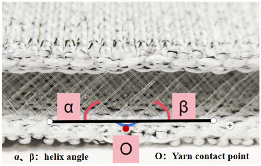
WKSF with spacer filaments arranged in an X-shaped pattern.
The raw materials used for the surface layer were 667dtex/192f polyester filament and 33.3/77.8 dtex core-spun yarn of PA/PU, which has good shrinkage and provides a stable constraint for the spacer monofilaments,23,24 which are polyester monofilaments with a diameter of 0.14 mm. The detailed parameters of the fabric are shown in Table 1.
Material and structural parameters of WKSFs.

α and β are theoretically equal in magnitude, but there are slight differences in the actual measurements. This difference may be due to uneven yarn fineness or different tensions applied on the machine, 25 resulting in imperfect symmetry of the spacer filaments on both sides of the same loop-gathering point. The monofilaments are lapped onto the loop posts of the surface loops in a loop-gathering manner, and the loop-gathering portion is almost covered and wrapped by the fluffy surface complex filaments from the outside and the inside, so that the spacer fabric is an internally constrained and complex three-dimensional structure, 26 with a high degree of anisotropy and nonlinear mechanical behaviour.27,28 However, by adjusting the spacer filament structure and material, it is possible to tailor the structure to meet the needs of the depth of indentation in terms of the resistance to compression, and therefore an in-depth understanding of the relationship between the compressive and structural properties of spacer fabrics is essential for the rational selection of WKSFs for specific applications.
Plate compression test
Plate compression experiments were carried out at an ambient temperature of (25±2)℃ and a relative humidity of (65±5)%, using a cylindrical plane platen with a diameter of 20 cm to extrude a specimen with a size of 100 mm × 100 mm at a speed of 20 mm/min, and the total compression displacement was set to be 80% of the initial thickness of the fabric, and the compression experiments are shown in Fig.2. The stress changes during compression were recorded. The stress change during compression was recorded, and the flat plate compression force-displacement curve shown in Fig. 3 was obtained.

State of the spacer layer at the initial stage of the compression experiment.
According to the change of stress-strain curve obtained from flat plate compression, it can be seen that the compression deformation of WKSFs can be divided into three stages: linear elasticity stage, platform stage, and densification stage, as shown in Fig. 3.

Compression-recovery curve of spacer fabric.
The compression work W is used to characterise the pressure-relieving ability of the fabric, the larger the value of W, the more difficult the fabric is to be compressed and deformed, and the better the pressure-relieving ability. The area between the pressure-displacement curve and the x-axis at the loading stage is the size of the compression work, which is calculated by the formula:

Where Xm is the thickness loss of the fabric when the maximum pressure is reached during compression and y is the force-displacement curve during the loading stage.
Interval fabric model establishment
Fabric structure simulation
In FEA calculations, structural simplification of the model is generally done in the studies due to the excessive amount of computation. The finite element analysis of spacer fabrics in previous studies was generally based on the Euler-Bernoulli beam theory, and a simplified model was built to predict the postbuckling behaviour of individual spacer monofilaments, ignoring the interactions between the spacer filaments. 29 In addition, many scholars oversimplified the finite element model for spacer fabrics with respect to the surface layer, retaining only its thickness, and then replacing the surface layer fabrics with an isotropic, equal-thickness flexible panel of the surface layer fabric. 30
In order to ensure the accuracy of the force analysis, the model developed in this paper retains the fabric surface loops and imposes interactions between the frictional constraint behaviour between the surface layer loops and the spacer filaments and the internal contact friction behaviour of the spacer filaments. This approach improves the accuracy of the finite element analysis results of the spacer fabrics, and at the same time the mechanical interaction between the fabric surface layer loops and the spacer filaments can be observed.
Before modelling, the following assumptions were made to facilitate the micro-geometric modelling structure, taking into account the complexity of the WKSF surface layer loop sheathing, as well as the fact that the yarns are in contact with each other and extruded during the weaving process, and that the yarn cross-section observed under the microscope is not circular but approximately elliptical:
(1) Assuming all of the surface multifilaments and the spacer monofilaments are circular in cross-section, and the shape of the cross-section remains constant everywhere and anytime even during WKSF is under compression.
(2) Assuming that the left and right spacer monofilaments of the X-shaped distribution are symmetrical along the axial direction, the inclination angles of the spacer monofilaments on both sides of the same loop collection point are equal.
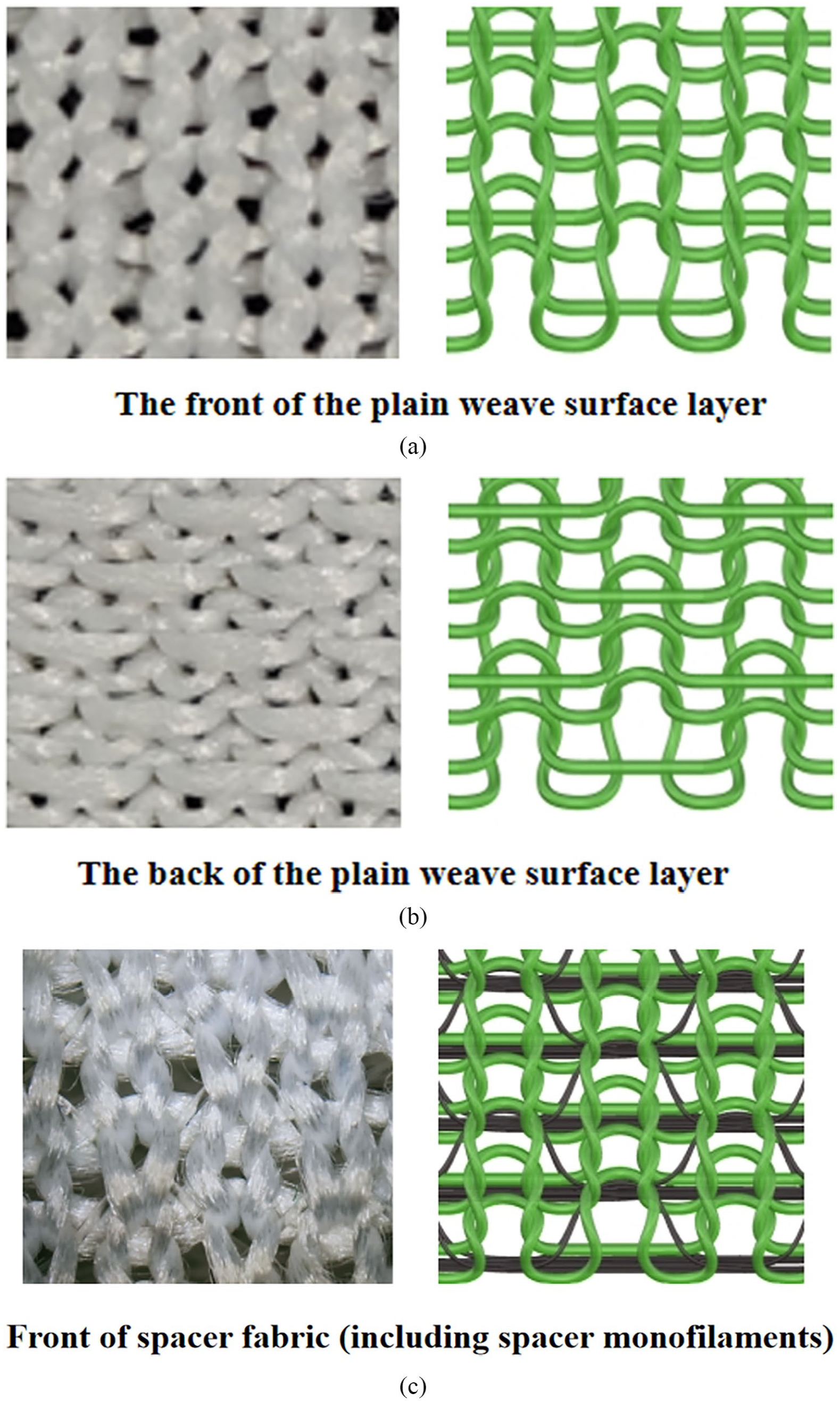
In order to ensure the consistency between the constructed model and the actual fabric, the real morphology of the spacer fabric was photographed from multiple angles using an optical microscope, and it has been determined that the surface layer contains two different weft-knitted coil structures, as shown in Fig.4(a). The stable Yarn loops of the surface layer were watched under the microscope and their characteristic points were extracted as the type value points. Eventually, nine feature points were selected on each loop and then connected using Bessel curves based on the observed pattern of loop threading, and finally, a model of the upper surface layer of the fabric was obtained as shown in Fig. 4(b).After the upper layer loops were drawn, its model was mirrored in the X-Y plane, and the mirror displacement is the actual measured fabric thickness, thus completing the establishment of the lower surface layer model. The spacer filaments are then sequentially connected to the surface loops according to a regular stitch, and the complete spacer fabric model is obtained by successive arrays, as shown in Fig.4(c).

Modelling of WKSF: (a) Two types of loop for surface layer; (b) 2D model of the upper surface layer; (c) Overall model of WKSF.
And connected by tracing through Bessel curves in space based on the observed coil threading pattern to obtain a model of the upper surface layer fabric, as shown in Fig. 4(b). After plotting the upper layer of coils, its model is being mirrored in the X-Y plane and the mirror displacement is the actual measured thickness of the fabric to complete the model of the lower surface fabric. Subsequently, the spacer filaments are being connected to the surface layer coils sequentially according to the bonding law of the real fabric, and the complete spacer fabric model is being obtained by successive arrangement, as shown in Fig. 4(c).
The minimum organisation loop in the figure is arrayed in the x and y directions to form the upper surface layer, and the symmetric lower surface layer is formed by mirroring the upper surface layer in the z-axis direction, and the connections are made in the upper and lower surface layers in accordance with the law of spaced filament-set loops in the physical figure.
A comparison between the physical figure and the model is shown in Fig. 5.
Real photos of fabrics and corresponding simulation images.
The completed WKSF model drawn in Rhino is shown in Fig.6 for the subsequent FEA process in Abaqus.
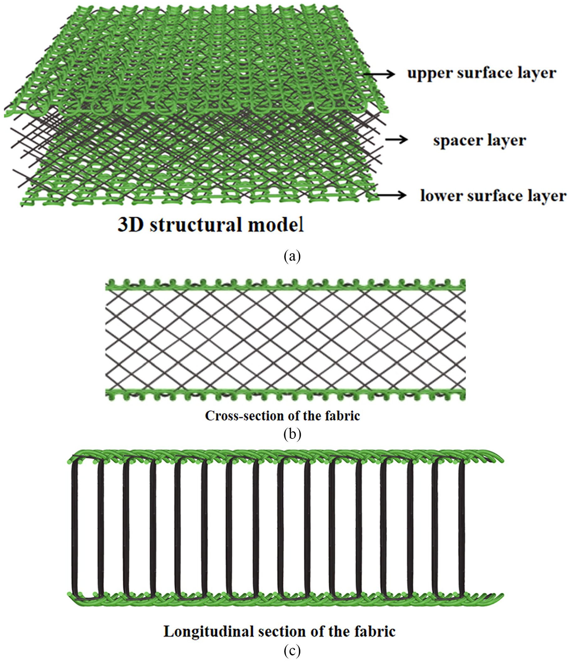
Demonstration of the WKSF model: (a) 3D structural model; (b) Cross-section of the fabric; (c) Longitudinal section of the fabric.
In order to ensure the convergence of the simulation results, the following assumptions are made before performing the finite element analysis based on the observation of the compression process.
(1) The spacer monofilament is an isotropic elastic material whose modulus and length remain constant during compression, and the plastic deformation during compression is negligible.31,32
(2) No lateral displacement occurs between the spacer monofilament and the surface during compression. Because the loops of the surface layer have strong staggered constraints on the ends of the spacer monofilament during compression deformation of the fabric, the possibility of lateral displacement during actual compression is very small.
Based on the above assumptions, after analyzing the spatial morphology of the spacer fibers, Rhino software and Abaqus software were used together to import the Rhino built model into Abaqus using the "geometric diagnosis" tool to check for invalid entities. After multiple adjustments and repairs of geometric defects, the fabric model shown in Figure 7 was obtained. The experimental sample is a 10cm×10cm square with a fabric thickness of 5.5mm and a spacer monofilament diameter of 0.14mm. To simplify the analysis and improve speed, an initial finite element model is established at a ratio of 10:1. Considering the possible self contact friction between the spacer monofilaments after bending deformation and the spacer monofilaments between the front and rear rows, the final simplified model retains 3 rows of spacer monofilaments and analyzes them using a 1/4 symmetric model, which reduces the time required for solving the initial full model by about 3/5.

Fabric model for finite element analysis.
Finite element model processing
Pre-processing of the model is required before performing finite element simulation calculations, including the assignment of material parameters, setting of analysis steps, defining interactions, imposing boundary conditions and mesh model delineation.
In order to obtain the performance parameters of the spacer fabrics, the following tests were carried out. Young's modulus was calculated from the stress-strain curve of polyester monofilaments and tested by Instron tensile apparatus. The friction coefficient was determined by Y151 fibre friction tester (Changzhou, China). Five measurements were taken for each parameter and simulations were performed using the average of the five measurements. The performance parameters of each component are shown in Table 2, and the actual material parameters obtained were assigned to each part of the model.
Model material parameters.

Due to the large amount of deformation in this model, the implicit analysis of Abaqus is only applicable to the simulation of small deformation state, so the explicit analysis of power is adopted, in order to shorten the computation time, a large-scale scaling is carried out, the analysis step time is set to be 0.01s, the compression rate is set to be 1200mm/s, and the mass scaling factor is set to be 1000.The interaction module is set to have two types of general contact and self-contact, the contact between indenter and surface layer is defined as general contact without relative motion, the friction coefficient is 0.3. The contact between the indenter and the surface layer is defined as a universal contact without relative motion, with a friction coefficient of 0.3. The contact between the spacer filaments is a self-contact, and the tangential and normal contacts are ‘penalised’ and hard contacts with a friction coefficient of 0.28, respectively. The ‘Tie’ constraint is set between the spacer monofilament and the surface layer, which is treated as a whole in the solution and does not need to consider the sliding or cracking problems between the contact surfaces, which can effectively reduce the computation time of the nonlinear solution and improve the accuracy of the calculation. 33
Finite element simulation usually needs to consider the boundary effects of the model, and the influence of boundary effects can be reduced by defining boundary conditions. In order to simulate the mechanical process of axial compression, a three-dimensional discrete rigid shell component is set up in Abaqus to simulate the indenter of the MTS test apparatus, and the origin is set as the constraint node to limit the fabric model, and the reference points RP-1 and RP-2 are selected in the upper and lower indenter respectively, and the loads and displacements are applied to the reference points.U1, U2 and U3 represent the translational degrees of freedom along the X, Y and Z directions respectively, and UR1, UR2 and UR3 represent the rotational degrees of freedom along the X, Y and Z directions respectively. UR1, UR2, and UR3 represent the rotational degrees of freedom along the X, Y, and Z directions, respectively. According to the actual experimental conditions, the indenter can only move along the z-axis, so the U3 of RP-1 is set to be 4.4mm in the load module, and the degrees of freedom in other directions are all 0. In order to prevent the following layer from moving, RP-2 is set to be completely fixed, and there are no degrees of freedom in all directions. The models of fabric and indenter are shown in Fig. 8.

Meshing of fabric and platen models.
The number of meshing directly affects the length and accuracy of finite element simulation, the more the number of meshes, the higher the accuracy of the finite element simulation results, but it will greatly prolong the computation time of the finite element. Therefore, it is necessary to choose a more appropriate number of meshes to divide the whole model. The meshing involves two mesh types, namely linear hexahedral structural cells (C3D8R) and nonlinear ten-node tetrahedral cells (C3D10). When the tetrahedral mesh is used, the yarn surface is pitted and uneven, and some of the joints are almost broken, with poor mesh quality; therefore, in order to simulate the yarn with uniform strips, and to improve the mesh quality while ensuring the good contact, the model is classified by C3D8R.The position of eight nodes of the C3D8R cell topology can be used to describe the complex shapes and the motion state, which is suitable for the analysis of large deformation. As the hexahedron has parallel and two pairs of boundary surfaces, its topology is simple and regular, easy to generate and process, and the displacement constraints on faces, edges and points can be realised by using the multi-point constraint function (MPC) in Abaqus software, which has a high accuracy and efficiency in calculation. Considering the balance of calculation accuracy and time, after several debugging, the grid seed size of the interval layer is set to 0.2, and the grid size of the surface layer is slightly larger, set to 0.5, and the meshing results are shown in Figure 8.
Finite element results and analysis
In this paper, with the help of Abaqus software, the failure mechanism and damage mode of spacer fabrics under flat compression load are studied, and the equivalent stress cloud diagrams corresponding to different compression amounts in the compression process of spacer fabrics are obtained, as shown in Fig. 9, which simulates the gradual process of the model from the stress to the yarn deformation damage. At 5% compression, the upper surface layer is stressed first, and stress concentration occurs in the exposed spacer filaments and the through-sleeve contact area of the surface layer loops, while the lower surface layer has no obvious stress change. When the compression amount is 20%, the stress starts to be transferred from the surface layer to the spacer layer, and the spacer monofilaments near the end of the upper surface layer shows irregular wavy bending deformation. Stress is concentrated in the spacer filament set circle bending and the surface layer of the spacer needle plain stitch needle knitting arc parts. At 35% to 65% compression, the deformation of the spacer filament near the lower surface layer occurs as the strain increases, the twist of the spacer filament continues to increase, and some of the spacer filaments come into contact with each other and friction occurs. The stress is transferred from the two ends of the spacer monofilaments to the middle, and finally distributed on the whole spacer monofilaments, with less stress at the two ends and maximum stress at the middle point. Compression amount of 80%, the spacer filament a large number of ‘inverted phenomenon’, bending close to the limit state, the fabric is compressed into a dense collection of fibres, 34 no longer occurs lateral displacement, along the axis of the force vertically downward collapse.

Fabric stress cloud at different compression amount: (a) 5%; (b) 20%; (c) 35%; (d) 50%; (e) 65%; (f) 80%.
In the whole compression process, the stress on the spacer monofilament is much larger than that on the surface layer, and the fabric damage mode is progressive bending breakage of the spacer filament. The point with the most concentrated stress distribution in the stress cloud diagram is the place where X-shaped WKSFs are most likely to be damaged under compression load.
The stress-strain curves obtained from the experiment and simulation are shown in Fig. 10, where the compressive strain is the ratio of compressive displacement to the original thickness of the fabric, and the compressive stress is the compressive load divided by the stressed area of the specimen. As can be seen from the figure, the stress-strain curves obtained from the finite element simulation and the actual compression experiments have similar trends, i.e., there are linear elasticity stage, plateau stage and densification stage. The simulation results are numerically slightly larger than the experimental measurements, which may be due to the following reasons.

Experimental and simulated stress-strain curves.
(1) The actual yarn has uneven stemming, and the model was built by idealising the yarn into a perfectly uniform stem.
(2) There are certain constraints and interactions between the spacer monofilaments and the surface layer, as well as certain connections and interactions between the monofilaments. The model simplifies the contact interaction and friction mechanism between the spacer monofilaments and the contact layer.
As shown in Table 3. Although there is a certain error between the simulation results and the experimental measurements, the relative error is less than 10%, which is within the acceptable range. Therefore, it is effective and sufficiently feasible to use the finite element model established in this paper to analyse the compression properties of spacer fabrics.
Experimental and simulation values.

Conclusions
Flat plate compression tests and simulation analyses were carried out on the WKSFs. By comparing the finite element simulation results with the experimental tests, it was demonstrated that the finite element model is sufficient to simulate the compression behaviour of the fabrics, and the compression properties based on the actual or pre-determined material properties can be predicted. The conclusions can be drawn as following:
(1) There is no obvious deformation of the surface layers during flat plate compression, and the main reason for the change in fabric thickness is the deformation of the spacer filaments.
(2) Under the action of flat compression load, the parts of stress concentration are, in order, the loop of the upper surface layer, the spacer filament exposed on the surface, the two end points of the spacer filament, and the middle point of the spacer filament has no obvious stress change in the lower surface layer.
(3) The failure mode of fabric pressure-relief is progressive bending breakage of spacer filament. The spacer filament is the main load-bearing body, with the increase of compression deformation, the spacer filament appears bending deformation, the stress is transferred from the two ends of the spacer filament to the middle, and the damage is concentrated at the middle point of the spacer filament.
Footnotes
Declaration of conflicting interests
The author(s) declared no potential conflicts of interest with respect to the research, authorship, and/or publication of this article.
Funding
The author(s) received no financial support for the research, authorship, and/or publication of this article.