
Abstract
Textile-based electromagnetic interference (EMI) shielding materials with good flexibility and high EMI shielding effectiveness (SE) are highly desirable. Still, the poor mechanical properties of textile-based EMI shielding materials limit their application. The carbon filaments (CF) combine superior mechanical properties and conductivity. Therefore, we demonstrate the CF-reinforced material, which was laminated with two types of copper-coated nonwoven polyester (CuPET10 and CuPET20) for EMI shielding. Compared to the traditional lamination method, this process was more convenient by ironing with adhesive lining. The developed laminate (CuPET/CF) performs superior EMI shielding property with an average SE value of 88.6 dB in the frequency range of 30 MHz to 3 GHz. The mechanical properties were improved from 12.7 to 39.9 MPa and from 13.46 MPa to 35.78 MPa for CuPET10/CF and CuPET20/CF, respectively. The newly developed material also demonstrated exceptional lightweight, flexibility, and thermal resistance. The laminated CuPET/CF material provides enhanced mechanical properties and easy lamination capability, allowing it to shield surfaces of electromagnetic radiation-sensitive equipment while providing a certain degree of protection and extremely high EMI shielding efficiency.
Introduction
A major current focus in electromagnetic interference (EMI) shielding textile-based materials is how to improve the overall EMI shielding and mechanical properties of the material while ensuring the material’s flexibility for preventing hazards to humans and protecting sensitive electronic devices from extra electromagnetic radiation.1–4 Numerous experiments have established that textile-based EMI shielding material has its own unique properties that make it an ideal EMI shielding material because of its lightweight, flexibility, and air permeability.5–9 Metallized textiles have garnered substantial utilization within the realm of electromagnetic shielding. This prevalence is attributable to the well-established processing methodologies associated with metallized textiles, as well as the profound progression in their development and production capacities, particularly concerning their integration within the subsequent domain of clothing industry applications.10–13 However, conventional textile-based coatings of metal particles on polymer fibers generally lack enough mechanical properties and exhibit limited EMI/ES reliability under large mechanical deformation due to the mechanical character of polymer fibers.14,15 Besides being high-strength, advanced textile-based EMI shielding materials are also requested to show good thermal resistivity to guarantee that electromagnetic wave-sensitive equipment runs at the proper temperature.16,17 This is important for their practical uses in EMI radiation protection, which require high SE, high mechanical properties, and a certain thermal resistivity.
The importation of carbon-based high-conductive material has emerged as a prospective avenue to improve the SE of EMI textile-based material, which offers exciting possibilities for enhancing the EMI shielding properties.18–20 Huynen et al. 21 developed the multilayered foamed nanocomposite with a graded concentration of carbon nanotubes, which could enhance 15 dB SE compared to the original samples. The two-dimensional metal carbides and nitrides, known as MXene, has generally accepted as effective nanoparticles for enhancing the EMI shielding property.22–25 Liu et al. 26 decorated the silk fabric with nanostructured silver nanowires (AgNWs) and transition metal carbide/carbonitride (MXene) nanosheets highly improved the EMI shielding property to 54 dB. Furthermore, in order to enhance the mechanical properties, various polymer coatings are applied to the surface of the conductive textiles. Jia et al. 27 developed the EMI textile-based material by integrating silver nanowires and conformal polyurethane layers on a carbon fiber fabric that could perform over 90 dB SE with enhanced mechanical properties up to 10 MPa. The EMI shielding property of the fabric could be improved by combining conductive fibers. Tunakova et al. 28 discovered that by combining stainless steel short fiber with woven fabric, the system performed around 30 dB SE, and the mechanical property was also improved after mixing the stainless steel fiber, as confirmed by the washing ability test. Some of the outputs focus on using conductive polymers and textiles to make composite materials.29–32 After the curing of the polymer matrix, although the mechanical properties were increased without a doubt, the flexibility of the material was lost, and normally the thickness of these composite materials is over 1 mm. Changing the geometrical structure could improve the SE by reducing the porosity and increasing the conductive layer thickness and conductivity,8,33–36 but for these methods, there is very limited contribution to enhancing the mechanical property.
The incorporation of conductive metal on textiles appears promising for improving EMI shielding performance.37–41 However, the enhancement of the mechanical property is very limited, and less research has studied the thermal property change after integrating the conductive material. The relatively complicated and time-consuming process severely limits its usage.
Carbon fiber was used widely for the application of EMI shielding due to their conductivity. Various research has studied the EMI shielding property of carbon fiber reinforced epoxy composites.42,43 In the context of developing EMI shielding composites, carbon fiber was incorporated as a reinforcing material. However, the inherent flexibility and softness of carbon fiber were compromised due to the resin curing process involved in composite fabrication. Consequently, the utilization of carbon fiber-based textiles for EMI shielding applications is not prevalent. Untreated carbon fiber fabrics are susceptible to issues such as fiber dispersion, which can detrimentally impact their mechanical properties and overall durability, thereby limiting their service life.
Herein, in this paper, two specifications of excellent EMI shielding performance textile-based laminated material with high mechanical property and good thermal property were fabricated via a highly efficient and easy-to-handle method. The newly developed laminated material is made up of a PET nonwoven textile with two types of copper nanoparticle coating (CuPET10 and CuPET20) and a carbon filament (CF) reinforcement layer. The lamination process was realized by using an adhesive lining between CuPET and CF, which was ironed in just 1 min. The integration of CF into conductive CuPET combined with excellent multifunctionality makes CuPET/CF an easy-to-fabricate, superior EMI shielding material with high mechanical performance that is desirable for applications under harsh circumstances. The newly developed material will be significant for designing realizable and valuable textiles and extending their lifespan for practical applications.
Experimental sections
Materials
The copper-coated non-woven polyester fabric has been successfully developed from our previous research via electroless plating method.11,33 To ensure the stability of EMI shielding performance from the EMI shielding material and a suitable sample size, two kinds of EMI shielding commercial nonwoven textiles, Meftex 10 and Meftex 20, were obtained with support from the Czech company Bochemie a.s. (Czech Republic). For brevity, in this paper, the Meftex 10 and the Meftex 20 were renamed CuPET10 and CuPET20, respectively.
The initial stage in the production of CuPET fabric involves the process of activation. To activate the fabric’s surface, an activation solution (CATAPOSIT44, supplied by Rohm and Hass company, Netherlands) was employed, and the activation was carried out at a temperature of 45℃ for a duration of 5 min. The fabrics were immersed in a 10% hydrochloric acid solution. Following activation, the treated fabric underwent a “roll to roll” copper metal deposition process. The pre-activated PET fabric was passed through a bath containing CuSO4. Like the electroless plating process, the copper nanoparticles adhered to the fiber surface through a reduction bath utilizing borohydride. This production process resulted in the formation of a continuous layer of densely packed metal particles (copper) on the fabric’s surface.
The carbon multifilament was purchased from Jilin Jinggong Carbon Fiber Co., Ltd. (China). The carbon filament (CF) was produced using the polyacrylonitrile (PAN) carbonization method. The single filament diameter is 6 μm. This kind of carbon filaments is suitable for composite material manufacture. The adhesive lining was using commercial hemming web (Korbond Hemming Web) purchased from the company Korbond (United Kingdom).
The basic parameters of greige fabrics were listed in Table 1.
Greige material information.

The laminated material was made by integrating two layers of CuPET on both sides of the parallel-arranged CF layer. Between the layers of CuPET and CF, the adhesive lining tape was placed. After the ironing process for the 30 s with the lowest temperature grade of the iron, the CuPET layer and CF layer were combined as an integral laminate material (CuPET 10/CF and CuPET 20/CF) (Figure 1).

(a) Lamination process and (b) layout of each layer of the laminated sample including the copper coated PET nonwoven (CuPET), adhesive lining and parallel arranged carbon fiber (CF).
In the context of mechanical properties analysis, careful consideration is given to the arrangement of carbon rovings, which are strategically oriented in a parallel manner with respect to the direction of the applied tensile force. This deliberate alignment serves a crucial purpose, as it guarantees the attainment of the utmost tensile strength along this specific force direction. By meticulously aligning the carbon rovings parallel to the tensile force direction, an inherent advantage is achieved: the elimination of any angular deviation between the direction of the applied force and the orientation of the carbon rovings within the material’s structure. This deliberate alignment strategy ensures an optimal utilization of the carbon rovings’ inherent strength and enhances the material’s resistance to tensile forces, thereby augmenting its mechanical performance.
Methods
Morphology and element characterization
The fabric thickness was determined using the EN ISO 5084 standard. 44 The thickness is defined as the vertical distance between the front and back of the fabric under a given pressure. 45 The fabric thickness meter with a presser foot diameter of 50 mm was measured in this paper, and the pressure applied to the fabric was 1.0 kPa. The area density of the fabric samples was determined using ISO 3801 standards, which included the length, width, and weight of the fabric samples. 46 It is known as grammage in the fabric industry and is measured in grams per square meter (g/m2) (GSM). 47
The surface morphology of the CuPET, CF, and CuPET/CF laminates was observed under scanning electron microscopy (SEM) (VEGA TESCAN Inc. USA) at 20 kV. The cross-section and the surface of the materials were observed.
EMI shielding effectiveness test
The EMI shielding effectiveness (SE) test was performed by the coaxial transmission line method according to the standard ASTM 4935-10. 48 Regarding this standard, it presumes a plane wave’s impact on a shielding material at frequencies from 30 MHz to 3 GHz. The measuring equipment was constructed with a coaxial specimen holder (supplied by Electro-Metrics, Inc., EM-2107A). The input and output signal were linked to a vector network analyzer from supplier Rhode & Schwarz ZNC3. The power ratio from the output and input signal can be used for calculating the SE (forward transmission coefficient S21) without and with shielding material.
The calculation equation is as follows equation (1):

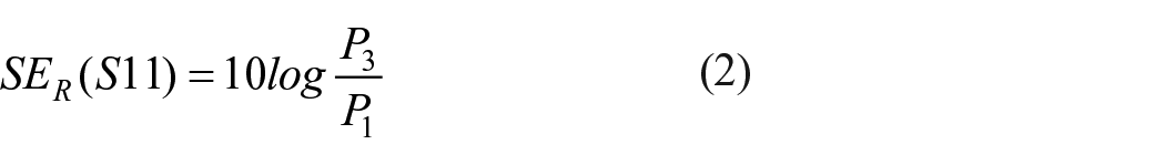
P1 is the received power unequipped with the shielding material, and P2 is the received power after inserting the shielding material present. The electromagnetic wave reflection coefficient SER (S11) interpreted that the electromagnetic wave signal from the transmitting antenna was reflected by the shielding material and received by port 1. The ratio of the receiving reflected electromagnetic wave power P3 and P1 calculates the input reflection coefficient by equation (2),
According to the transmission line theory, the total SE can be calculated by the following equations in equation (3):

In equation (3), SE is shielding effectiveness, SER is direct reflection loss, SEA is absorption loss, and SEM is multiple reflection loss. The shielding mechanism known as multiple reflections (SEM) involves the occurrence of reflections at various surfaces or interfaces within the shield. This mechanism relies on the presence of a substantial surface area or interface area in the shield. For instance, porous or foam materials can serve as examples of shields with a large surface area. The loss resulting from multiple reflections can be disregarded when the distance between the reflecting surfaces or interfaces is considerably greater than the skin depth. 49 Usually, the factor SEM can be ignored when the SEA > 10–15 dB. It is usually only significant when the shielding material is thin and at low frequencies (i.e. below approximately 20 kHz). 50
Tensile test
The samples were prepared according to ASTM D 5034 51 using Tira TEST 2300 machine. Rectangular bars with 50 mm length were tested repeatedly five times. For each group, the average value was taken to calculate the tensile strength and initial modulus, and a 95% confidence interval was calculated to analyze the statistical significance. For adhesion force test the sample was specially designed as descripted in chapter 3.4.
Thermal conductivity
The Alambeta device was chosen as the measuring instrument of the samples’ thermal conductivity and thermal resistance. The principle of the device is calculating the heat flows that come through the tested samples due to the different temperatures between the bottom measuring plate and the head plate during the measurement time. After the samples are placed on the measuring bottom plate, the head plate will go down and touch the fabric samples with a pressure of 200 Pa. The heat flow values are processed in the integrated computer, and the measured samples’ thermal properties are finally calculated. The measurement ambient temperature was 23°C, and relative humidity was 40%. Each sample was tested five times at different points, and the average value and 95% confidence interval were calculated.
Results and discussion
Morphology analysis
The geometrical information of the laminated sample is listed in Table 2.
Laminated material information.

The mass per unit area and sample thickness both increased after the CuPET/CF lamination operation. The thickness of CuPET10/CF and CuPET20/CF, compared to the original thickness of CF, increased from 0.3 to 0.39 and 0.45 mm, respectively. Due to the ultrathin structure of CuPET, compared with CF’s original thickness, the increased thickness is very limited, which enables the laminated material to be integrated into the sandwich structure in future applications. The mass per unit area is mainly contributed by CF. However, the bulk density of both laminated materials is smaller than water (Figure 2). The lightweight and relatively thin structure makes the laminated material more widely applied.

CuPET/CF samples floated on the water, indicating the bulk density of both laminated CuPET/CF is smaller than water.
The samples’ surface morphology was presented in Figure 3. The CuPET10 and CuPET20 presented the porous structure and irregular fiber distribution that are typical of nonwoven fabrics (Figure 3(a) and (b)). The different orientation (not a regular net) is primarily due to industrial fabrication inaccuracies. This structure and orientation of fibrous elements cannot be changed because of solid spots, and therefore the real structure is an indication of deviation from the ideal net. The horizontal and vertical fibers were connected via thermal bonding technology, and the bonding points were more obvious on the CuPET20 surface (Figure 3(b)).

SEM pictures of (a) CuPET10, (b) Cu/PET20, (c) surface morphology of CuPET10, (d) cross section of carbon filaments, (e) laminated sample CuPET10/CF, (f) laminated sample CuPET20/CF, and (g) cross section of laminated sample CuPET10/CF.
The copper particles were distributed continuously and evenly on the surface of the PET fiber (Figure 3(c)), which is significant for maintaining good electrical conductivity and EMI shielding properties. The carbon filaments were constructed from single-strand carbon fiber. A single carbon fiber has a diameter of 6 μm. During the ironing process, the interlayer adhesive lining was melted and attached to the CuPET layer and CF layer, which can be observed in Figure 3(e) and (f)’s high reflection part. Between the CuPET fiber, the CF filament is neatly arranged and can also be observed. Figure 3(g) shows the cross-section structure of the laminated sample; the different layer layouts can be clearly identified.
EMI shielding effectiveness enhances
Three times test for each sample was performed. The EMI shielding effectiveness (SE) was measured in the frequency band from 30 MHz to 3 GHz. This frequency band is widely used for telecom communication and is also the main frequency band that has potential health hazards for humans and electromagnetic interference damage to precision electromagnetic instruments after a long time being closed to the electromagnetic wave excitation source. 52 The main mechanism of EMI shielding is reflection, absorption, and multireflection in the material. 7 The discontinuity of the impedance at the interface between the air and the metal causes this effect. This kind of reflection does not require the shielding material to have a certain thickness but only requires discontinuity at the interface. The energy that is not reflected by the surface and enters the shielding body is attenuated by the shielding material in the process of forward propagation in the body. That is the so-called absorption. When the remaining energy that has not been attenuated in the shielding body is transmitted to the other surface of the material, it will reflect again when it encounters the interface of metal-air impedance discontinuity and return to the shielding body again. This reflection may have multiple reflections at the interface of two metals.
Regarding samples CuPET10 and CuPET20, the SE values are around 49 and 58 dB, respectively (SE T value in Figure 4(a) and (b)). The higher copper content of CuPET20 caused the difference due to the difference in the fabric porosity. Normally the SE R value and SE A value reflects the material potential for reflecting and absorbing electromagnetic wave energy. More precisely, the SE R value presented the EM energy attenuation after the EM wave encountering the first interface, SE A presented the EM energy attenuation after the EM wave encountering the second interface. However, the thickness of both materials is extremely low, and the conductive particles are copper. Hence, the EMI shielding behavior of both samples presented high reflection attenuation and absorption attenuation. For carbon-based EMI shielding material, the total SE is around 18 dB, which is much lower than CuPET fabric.

EMI shielding effectiveness test in the frequency band from 30 MHz to 3 GHz results of (a) CuPET10, (b) CuPET20, (c) CF, (d) CuPET10/CF, and (e) CuPET20/CF.
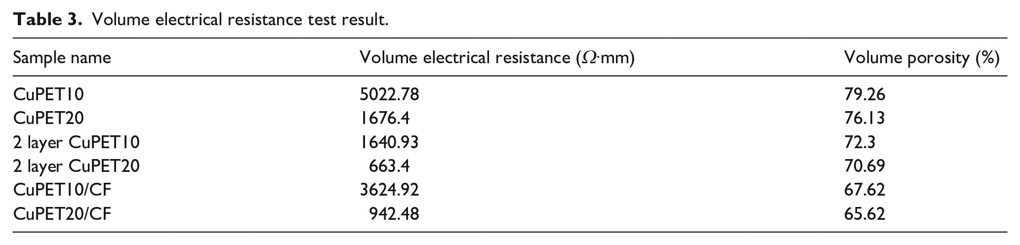
After laminating the material, the SE was improved significantly. The average SE in the tested frequency band of CuPET10/CF is 52.1dB and for CuPET20/CF is 88.6dB. Compared to the double layer of CuPET10 and CuPET20, the SE of the laminated sample is even higher (Figure 4(d) and (e)). The multilayer structured EMI shielding material has been studied via our previous research. 53 The main reason for the enhancement of SE for double-layered structures is due to the increased material thickness and reduced porosity. The volume porosity is calculated from the fiber volume ratio. In this calculation, we assume the mass of fiber equals the mass of fabric, the calculated value presented in Table 3. After the lamination, the material thickness increased significantly, and the porosity decreased. At the same time, the volume resistance of CuPET/CF samples also decreased compared to CuPET samples (Table 3). Even the volume of electrical resistance of CuPET/CF was higher than two layers of CuPET. Still, considering the changes in thickness and porosity, the total shielding effectiveness of CuPET/CF higher than Cu/PET is reasonable.
Volume electrical resistance test result.
To judge whether the average SE difference between the CuPET and CuPET/CF is significant or caused by random error, the statistical analysis method of two-sample t-test was performed. The significance level α = 0.05, and each SE result from two layers CuPET sample and CuPET/CF laminated sample on the same selected frequency points (30 MHz, 100 MHz, 200 MHz, 300 MHz. . .3 GHz) were compared. The null hypothesis is given as:

This hypothesis means the average SE value of two layers CuPET μc is equal to the average SE value of CuPET/CF μm.
The alternative hypothesis is defined as:

The p-value of the t-test is listed in Table 4.
p-Value of two-sample t-test for two layers CuPET SE value and CuPET/CF SE value.

The t-test result presented a significant difference between the SE value of two layers CuPET and laminated CuPET/CF, which p-value is less than 0.05. This conclusion proof again that the laminated samples presented improved EMI shielding property compared to the greige copper plated polyester nonwoven samples.
There is exist of multiple reflection for laminated sample CuPET10/CF and CuPET20/CF which can be distinguished the from the shape of the SE single which presented in Figure 4(d) and (e). There is a jagged signal in the test frequency band. Such a shape may be due to the interference formed by the internal reflection of the electromagnetic wave on the output signal.
Regarding the percolation threshold for electrical conductivity, the investigation focused on analyzing the percolation threshold for electrical conductivity in polymer matrices incorporating conductive additives such as carbon-based particles and metal particles. The concentration and distribution of these conductive additives played a critical role in determining the percolation threshold for electrical conductivity. Below this threshold, the material exhibited insulating behavior with minimal electrical conductivity. However, once the percolation threshold was reached or surpassed, the conductive pathways interconnected, facilitating efficient electron flow and resulting in significant electrical conductivity.
In this study, a CuPET/CF laminate was fabricated using two different conductive materials. The excellent conductivity of the laminate was demonstrated through the volume resistivity values presented in Table 3. A primary objective of this research was to highlight the favorable electromagnetic interference (EMI) shielding properties of the CuPET/CF laminate. It is well known that conductivity is a crucial parameter influencing the shielding effectiveness (SE). While the conductivity of the individual raw materials (CuPET and CF) remained unchanged, the lamination process led to an enhanced conductivity in the newly fabricated sample (Table 3). This increase in conductivity contributed to the improved SE observed in the newly laminated sample.
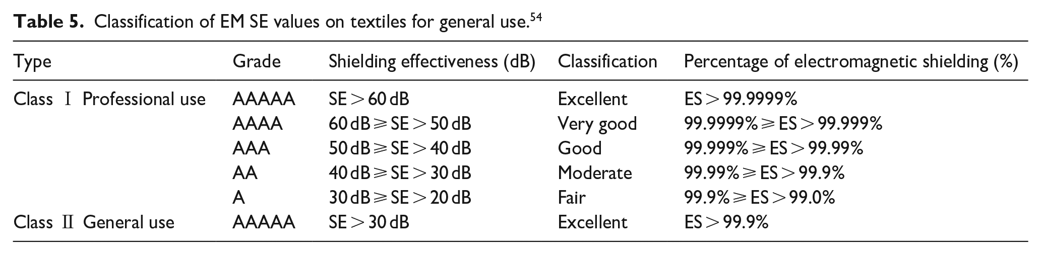
All CuPET and CuPET/CF samples, according to the classification evaluated in the “excellent” category for Class Ⅱ general use. Regarding Class Ⅰ Professional use, CuPET10 fulfills the SE requirements of grade “AAA” (Good), and CuPET20 fulfills the SE requirements of grade “AAAA” (Very good). For sample CuPET10/CF and CuPET20/CF will fulfill the highest grade, which is “AAAAA” (Excellent) 9 (see Table 5).
Classification of EM SE values on textiles for general use. 54
Surface electrical resistivity after bending
One of the advantages of this laminated material is flexibility. This property made the material suitable for wider applications, which require EMI shielding material with good deformation property. For conductive materials, the surface electrical conductivity could be influenced due to conductive medium discontinuities caused by bending. In this case, the reduced electrical conductivity could influence the EMI shielding performance. In this case, it’s essential to test the surface’s electrical resistivity after bending cycles.
This test was realized via the surface electrical resistance measurement of a multimeter integrated with an electrode clamp at a 20 cm distance. For each bending cycle, arch the midline of the sample at 90° by pushing the sides of the sample with both hands, then pull the sample back into its original position (Figure 5(a)). The surface electrical resistivity could be calculated from the reading of a multimeter and the measured sample area. The variation of surface electrical resistance with repeated bending for both the laminated sample with the same bending cycles is plotted in Figure 5(b). CuPET10/CF has a higher surface electrical resistance line than CuPET20/CF, indicating that the sample CuPET20/CF has a higher electrical conductivity than CuPET10/CF. This result was also approved based on the volume electrical resistance test and EMI shielding test results. From 0 to 300 bending cycles, the CuPET10/CF sample exhibits stable electrical resistivity at 0.02 Ω/sq. After 300 bending cycles, the surface electrical resistivity CuPET10/CF samples is slightly increased to 0.025 Ω/sq. Similar to CuPET10/CF, the surface electrical resistivity of CuPET20/CF was stable before 450 bending cycles but slightly increased after 500 bending cycles. The possible reason for the increased electrical resistivity may be caused by the fiber cracking after bending cycles, which has already been approved by other research.55,56 The laminated sample exhibits generally stable electrical conductivity after bending cycles. This test result indicates good potential for using the developed material for a long time.

Surface electrical conductivity change after hand bending cycles of sampleCuPET10/CF and CuPET20/CF: (a) measurement method and (b) surface electrical resistivity changed in 500 bending cycles.
Force of adhesion and tensile test
Regarding the laminated sample, the adhesion force is important to present the firmness between each layer of material. For CuPET/CF laminated material, the adhesive lining working on the interface between the CF layer and CuPET layer. To measure the adhesion force, the test sample was specially designed as one part separated layers (7 cm) and the left part as laminated sample (5 cm). The width of sample was kept as same as tensile strength test requested as 5 cm. The separated layers were fixed on the tensile machine clips. During the tensile process, the layers were separated, and the maximum adhesive force was recorded in Table 6.
Average maximum adhesion force of the different layers for laminated sample.

After the testing of adhesion force for CuPET10-CF and CuPET20-CF, the CuPET sample was totally teared, but part of the CuPET fibers were still attached on the CF surface. This result indicates that the adhesion force between CuPET and CF is higher than the tear force which can break the CuPET structure. To test the maximum adhesion which the adhesive lining could offer for textile structure, the PET woven fabric strip (100% PET, plain weave, yarn count for warp/weft are 10 tex and 16 tex) was prepared as same size as other adhesion force testing sample. By same testing procedure, the structure of PET woven fabric strip kept integral after the tearing process. In this case, the maximum adhesion force which the adhesive lining could offer to the PET fabric was measured as 10.53 N, which is higher than separating tear force between CuPET and CF (3.16 N for CuPET10-CF and 4.37 N for CuPET20-CF). This result demonstrates that the adhesive lining could offer satisfied adhesion force for the laminated sample and ensure the firmness of each laminated sample layer.
One of the main reasons to integrate the CF into the CuPET system is to enhance its mechanical properties. The mechanical properties of Cu-coated PET fabrics were too weak and limited the applications filed. After laminating with CF, the mechanical tensile strength property was significantly improved. The measured results are presented in Figure 6.

Tensile strength test result: (a) CuPET10 tensile stress and strain curve, (b) CuPET20 tensile stress and strain curve, (c) CF tensile stress and strain curve, (d) CuPET10/CF tensile stress compare to CF tensile curve, (e) CuPET20/CF tensile stress compare to CF tensile curve, (f) average tensile strength value, (g) average elongation at break point, (h) average initial module, and (i) average tensile breaking force.
According the tensile strain stress curve, CF performs superior tensile stress compare to CuPET samples. It’s clearly that the mechanical property of carbon filaments is superior compare to PET fabric, the tensile breaking force of CF is far greater than CuPET samples (Figure 6(i)). The tensile strength of CuPET10 and CuPET20 are 12.7 and 13.46 MPa respectively, for CF the tensile strength is 563.11 MPa (Figure 6(f)). The elongation of CF is lower than CuPET samples, which is decided by the character of carbon filaments (Figure 6(g)). The initial module of CF is higher than CuPET samples also determined by the rigidity of carbon filaments (Figure 6(h)).
After the lamination process, the CuPET/CF sample exhibits improved tensile properties (Figure 6(d) and (e)). For CuPET10/CF and CuPET20/CF, the tensile strength can reach 39.9 and 35.78 MPa, respectively. It should be noted that, when checking the tensile strength, the laminated sample performs much lower value as CF sample (Figure 6(f)), but the tensile force is higher than CF sample(Figure 6(d), (e) and (i)). The tensile strength is calculated via the tensile force divided by the cross-section area. Due to the increased thickness after the lamination process, the cross section will also increase. In this case, the calculated tensile strength of laminated samples will be lower than carbon fibers’ value, even though the breaking force is higher.
The change in elongation at the break point shows that after the lamination process, the sample’s elongation property is reduced (Figure 6(g)). It’s understandable that the CuPET layer and CF layer were combined via adhesive lining material, during the tensile process, the tensile deformation was limited by the melted adhesive lining (Figure 6(g)). There is no mathematically significant change in the initial module of laminated samples compared to the CuPET samples (Figure 6(h)).
This tensile test is in the CF direction. That is why the laminated sample could withstand tensile forces comparable to carbon fiber. Given the material costs and sample thickness, it is reasonable to use carbon fiber filaments rather than carbon fabric as a reinforced material. It is obvious that if the tensile test is carried out again in the direction perpendicular to the tensile force of the carbon fiber, the value will be much smaller than that measured by the force along the direction of the fiber. In the application of materials, the actual stress environment should be considered to determine the structure of reinforced CF materials. This content will not be discussed in depth in this paper.
Thermal conductivity
Thermal resistance described the ratio between the temperature difference at both ends of the object and the power of the heat source when heat is transmitted on the object. The value of thermal resistance R [K⋅m2/W] can be calculated according to the thickness of the material L[m] and thermal conductivity k [W/(m·K)] in equation (4)

According to this formula, it can be known that the thermal conductivity of the same material is constant, and the greater the thickness of the material, the greater the thermal resistance. This conclusion was approved in the result presented in Figure 7(a) and (b). With the increased layers of Cu/PET, the thermal resistance is increased in liner growth. The linear slope of thermal resistance and thickness reflected the thermal conductivity of the material. However, the measured thermal conductivity is slightly higher than slope value of thermal resistance and thickness in linear regression formula. The slope value for CuPET10 and CuPET20 are 0.0296, 0.0269 respectively. This value is very close to the thermal conductivity of air, which is 0.023–0.026 W/(m·K). However, as a polyester fiber based solid material, CuPET is expected to have a higher thermal conductivity compared to air. In this case, using the slop value to interpret the thermal conductivity is inaccurate. The measured thermal conductivity value is presented in Figure 7(c).
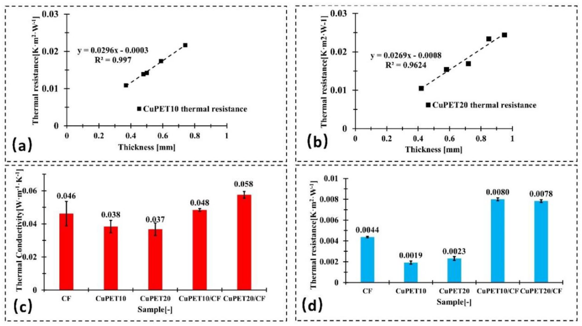
Thermal properties test result: (a) thermal conductivity test result of CuPET10 from four layers to eight layers, (b) thermal conductivity test result of CuPET20 from four layers to eight layers, (c) thermal conductivity test results of single layer material, and (d) thermal resistance test results of single layer material.
Regarding the thermal conductivity, the increased mass per unit area and mass of copper particle for CuPET20 not enough to make significant impact on the thermal conductivity changing compared to the sample CuPET10, the difference could be caused by the experimental error or heterogeneous of the sample since the error bar for both samples were overlapped. However, after the lamination process, the thermal conductivity of CuPET20/CF is higher than that of CuPET10/CF, and this result is mathematically significant. This result is determined by the porous structure of CuPET samples. CuPET10 has a higher porosity than CuPET20, implying that a CuPET10 sample may contain more air than a CuPET20 sample. The same results can be checked in Table 3: the volume porosity of CuPET10/CF is higher than CuPET20/CF. The thermal conductivity of air is lower than that of polyester fabric. In this case, the CuPET20/CF contains less air than the CuPET10/CF, so the thermal conductivity value of the CuPET20/CF can be higher than the CuPET10/CF (Figure 7(c)). In Figure 7(d), the thermal resistance value was compared. CuPET/CF samples after lamination have higher thermal resistance properties than unlaminated CuPET and CF samples. This is mainly caused by the increased thickness of the sample. There is no mathematically significant difference between CuPET10/CF and CuPET20/CF, even though their thermal conductivity values are different. Because of the variation in material thickness, the gap between their thermal conductivity is compensated by increased thickness. Considering the application for electromagnetic radiation and temperature-sensitive equipment, the laminated samples perform well, preventing heat loss while at the same time shielding the extra electromagnetic interference.
Conclusion
This study set out to develop a textile-based and carbon filament laminated material for EMI shielding applications with improved mechanical properties. The main goal of this study is to fill the gap between poor mechanical properties and superior EMI shielding effectiveness of textile-based EMI electromagnetic shielding materials via a convenient lamination method. By using the adhesive lining, the carbon filament is attached tightly to the copper-coated nonwoven polyester via the ironing process. The developed laminated material maintained a low density, which is less than water, and performed superior EMI shielding effectiveness of about 52.1 dB (CuPET10/CF) and 88.6 dB (CuPET20/CF). Due to the good mechanical properties of carbon filaments, the laminated material has improved mechanical properties; the tensile strength can reach 39.9 MPa (CuPET10/CF) and 35.78 MPa (CUPET20/CF) and the breaking force can reach the same level as carbon filament at around 900 N. The laminated material is also flexible; after 500 hand bending cycles, the conductivity of the material remained satisfactory. The thermal resistance improved as the thickness increased.
The findings of this study open up the possibility of incorporating carbon filament into an EMI shielding textile to improve its mechanical properties and EMI shielding effectiveness. The developed material would have potential for future EMI shielding applications that request higher mechanical properties and thermal resistance properties.
Footnotes
Declaration of conflicting interests
The author(s) declared no potential conflicts of interest with respect to the research, authorship, and/or publication of this article.
Funding
The author(s) disclosed receipt of the following financial support for the research, authorship, and/or publication of this article: This work was supported by the by the Czech Science Foundation (GACR)-project Advanced structures for thermal insulation in extreme conditions (Reg. No. 21-32510M).