
Abstract
In this work, the finite element software (ABAQUS) was used to build a single-cell model based on three-dimensional woven reinforced composite and investigate the propagation of stress waves in the composite. The experimental results of the edge part of the bullet after impact with the results of simulations were compared, and the final damage pattern of three-dimensional woven reinforced composite with commonly used laminates were also comparatively studied. The results indicated that the peak stress of the bullet in the three-dimensional woven reinforced composite increased with increasing incident velocity and was reflected back and forth. The fracture of the reinforcement yarn was rougher after the bullet was ejected from the lower surface of the three-dimensional woven reinforced composite than from the incident upper surface. Delamination did not occur within the three-dimensional woven reinforced composite, and the observed damage holes were generally consistent with the graphs simulated using finite element software. The research in this paper provides a design method for the application of three-dimensional orthogonal hybrid woven reinforced composites in ballistic protection. The experimental results and corresponding calculation methods can guide the design of high-performance protective armor.
Introduction
With the development of society and the economy, the actual demand for fiber-reinforced composite is also increasing.1,2 The mechanical, physical, and chemical properties of fiber-reinforced composites have been greatly improved and enhanced compared to the commonly used single conventional reinforced panels, greatly solving technical problems in mechanical engineering that cannot be solved with conventional material.3,4 In contrast to traditional engineering material, it has a number of properties such as lightweight, high specific modulus, high specific stiffness, high specific strength, impact resistance, good elasticity resistance, etc.5,6 Its research and development have always received great attention in various sectors of the national economy and defense protection such as construction and transportation, aerospace, military industry, and engineering bearing.7,8 Many researchers had found that delamination damage was the main form of ballistic impact damage in planar laminated composite, which was obviously different from the energy absorbed within the composite simply due to filament fracture and resin matrix cracking, so if a three-dimensional textile structure was used to prepare three-dimensional woven reinforced composites which have a stronger impact damage limit than laminated composites (laminates).9,10 At present, the equipment for producing three-dimensional orthogonal woven fabrics at home and abroad adopts the multi-layer shed technology (loom), that is, the warp yarn and the binding warp yarn are divided into multiple layers by the opening mechanism on the loom.
Research into three-dimensional textile materials has continued, and composites are becoming more diverse. With the advantages of high specific strength, good fatigue resistance, and designability, three-dimensional textile composites have gradually replaced traditional materials and are used in aerospace, civil engineering, construction, and fan blades. There have been many studies on the mechanical properties of three-dimensional woven reinforced composites. For example, Arendts et al. 7 compared three-dimensional woven composites with laminated reinforced composites in terms of tensile, compression, interlaminar shear, and impact resistance. Cox et al. 11 investigated three-dimensional woven reinforced composites regarding tensile, compressive, and flexural damage mechanism. It was concluded that the tensile damage of three-dimensional reinforced composite was mainly due to the brittle breakage and extraction of filament fibers, the compression damage was mainly due to the delamination of the kink band formation, and the bending damage of the composite was a combination of the above two forms of damage. Kier et al. 8 prepared fiber-reinforced thermoset composite with flax and basalt fibers and their hybrids as reinforcement and vinyl resin as matrix and found that the material had good impact properties. However, compared with thermoplastic fiber-reinforced composite, fiber-reinforced thermoset composites still have disadvantages such as high density, poor fracture toughness, and low strength. 12 Obviously, the current research on ballistic impact three-dimensional woven reinforced composites performance was basically focused on the laminated composite, or the study of three-dimensional textile orthogonal woven reinforced composite’s tensile and bending properties, the research involving three-dimensional woven reinforced composites on ballistic impact performance is still rare.13,14 Liu et al., Kazemianfar et al., and Ashok Kumar et al. used finite element to simulate and comparatively analyze the impact resistance of 3D and 2Dwoven fabric reinforced composites under low-speed impact. The structure indicated that the simulation results were highly consistent with the experimental results15 –17; Rupp et al., 18 Thomas and Tiwari, 19 and Feng and Aymerich, 20 etc. used finite element software to simulate and analyze the shape of different structural reinforced composites after impact, and they found that the simulation results were basically the same as the actual failure shape. It can be seen that the finite element software can be used as an effective means to simulate and analyze the impact performance of woven reinforced composite.
This paper focused on the bullet impact performance of three-dimensional woven reinforced composite, using the finite element software(ABAQUS) to establish a ballistic impact model, analyze the occurrence of bullet propagation of stress waves in three-dimensional woven reinforced composites, compare and analyze the experimental results of the edge part after bullet impact and the results of simulation calculations, and compare the final damage mode of three-dimensional woven reinforced composite with commonly used laminates. We provides a design method for the application of three-dimensional orthogonal hybrid woven reinforced composites in ballistic protection. The experimental results and corresponding calculation methods can guide the design of high-performance protective armor.
Material and model
Material
The three-dimensional woven reinforcement has two advantages: the warp and weft yarns are regularly staggered in the horizontal plane to maintain the planar properties of the composite skeleton, and the structural yarn bundles connected to them play a stabilizing role in the connection.21,22 This group of yarns in the thickness of the three-dimensional woven reinforcement mainly maintains a high shear strength between the different layers of the reinforced composites, reducing delamination and thus improving the impact resistance of the composite.23,24 The structure of the three-dimensional woven reinforcement was shown in Figure 1. The warp, weft, and Z yarns were independent and perpendicular to each other so that the yarns are completely straight and there was no tangling, and the warp and weft yarns remained in the same plane.

Structure diagram of three-dimensional reinforced woven fabric.
The Z yarn used in this study was a twist-free Twaron aramid fiber developed in Taiwan, and the warp and weft yarns used were twist-free alkali-free E glass fibers processed by Beijing Tianxing Ceramic Composites Co. Ltd., and their basic parameters were shown in Table 1. It used 307-3 unsaturated polyester resin developed by Wuxi Yangtze River Delta Assembly Manufacturing Co. It can produce a glued joint under the initiation of a curing agent and has high water resistance. The curing agent was chosen from methyl ethyl ketone peroxide, the accelerator was chosen from cobalt octanoate, and the solution mass configuration ratio of 307-3 unsaturated polyester resin, methyl ethyl ketone peroxide and cobalt octanoate was 100:5:3.25,26
Specifications of three-dimensional reinforced woven fabric.

Processing of three dimensional orthogonal woven fabrics
The processing diagram of three-dimensional orthogonal woven fabric is shown in Figure 2. After the four layers of warp yarns are stretched parallel to each other and penetrate into the loom, four layers of warp yarns that are not in contact with each other and parallel to each other are formed, and then the five weft yarns are driven by the rapier along the direction perpendicular to the warp yarns It is fed back and forth and through the five gaps formed by the warp layer and the Z yarns of the upper and lower layers. The Z yarns are interwoven at 90° up and down in the space where the warp yarns and the weft yarns are located. The resulting fabric does not move the warp yarns like a two-dimensional fabric, but moves parallel to each other, thereby reducing the wear and tear of the warp yarns. The up and down movement of the two rows of healds is used to drive the Z-direction yarns to move up and down to bind the entire fabric, minimizing the damage and breakage of the yarns. From Figure 2, we can see the cross-sectional structure of the three-dimensional orthogonal woven fabric. The yarns on the three systems of warp, weft, and Z yarn are vertical each other. There is no entanglement and curl between the yarns. The warp and weft yarns are arranged vertically in the plane.
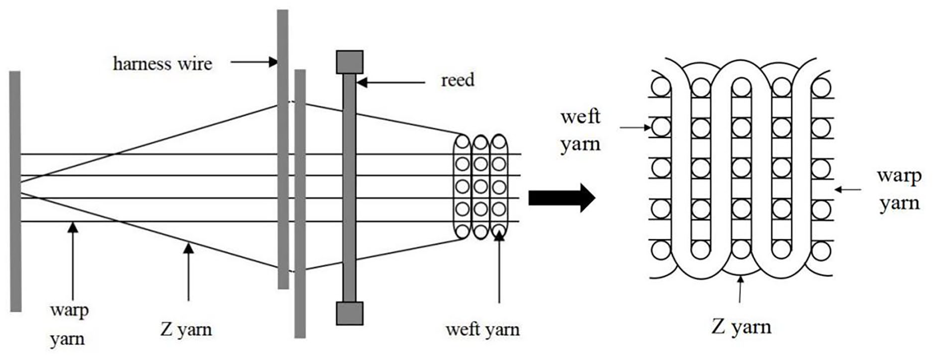
The processing diagram of three-dimensional orthogonal woven fabric.
Molding of three-dimensional woven reinforced composites
The three-dimensional woven reinforced 307-3 unsaturated polyester resin composites were prepared by vacuum-assisted resin molding method, VARTM (vacuum assisted resin transfer molding) technology, injecting the resin solution into the three-dimensional woven fabric, as shown in Figure 3 below.27,28 In order to ensure that the surface above and below the material was flat and does not affect the results of the later experiments, a thickness of 9 mm glass was placed on top of the three-dimensional woven reinforcement, which was essentially the same size.29,30 In order to facilitate performance testing and the production of test specimens, the thickness of the prepared reinforcement was maintained at approximately 12 mm. The cured and molded composite and its cross-section were shown in Figures 4 and 5.

Schematic diagram of VART preparation.

Front view of 3D woven reinforced composites.

Warp section of 3D woven reinforced composites.
Ballistic impact system model
Modeling and calculation methods
Based on the microscopic properties of three-dimensional woven reinforced composites, this time a single-cell model of the composite was created, as shown in Figure 6 below, and the composite was impacted with bullet incidence velocities of 749 and 658 m/s to study the impact deformation and damage produced by the bullet inside the composite. Because the microstructure of the three-dimensional woven reinforced composite was inhomogeneous, this can be approximated as a continuous macroscopic medium. In combination with the FORTRAN language, a single-cell model VUMAT interface procedure was used based on the elastic-plastic transient relationship, where the critical failure area criterion and the maximum stress criterion were the main principles used. VUMAT was also used with the finite element package ABAQUS to calculate the stress updates for each three-dimensional woven reinforced composite component on an explicit algorithm, numerically simulate the ballistic impact, and finally obtain the finite element calculation results.

Finite element model of ballistic impact.
Determination of material parameters
In the three dimensional woven reinforced composite specimens, the relevant technical parameters for the unsaturated polyester resin, glass fibers, aramid fibers, and the elastomer were shown in Tables 2 to 6 below.
Technical data of 307-3 unsaturated polyester resins.

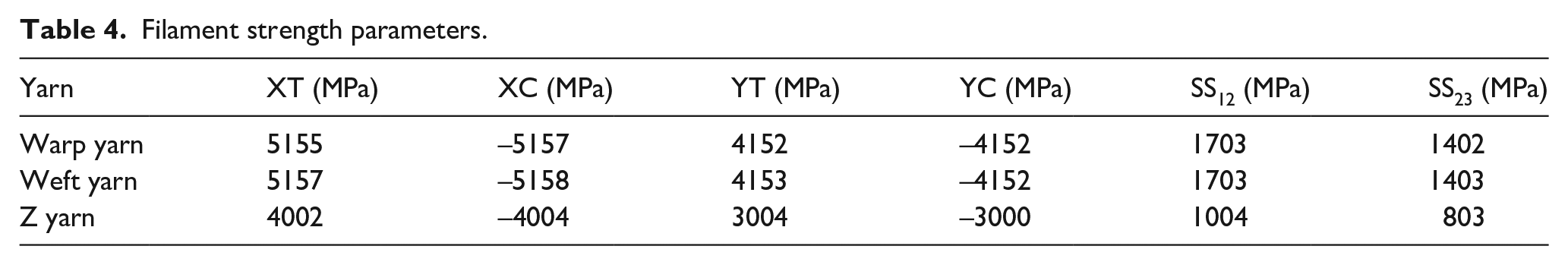
Filament stiffness parameters.

Filament strength parameters.
Basic mechanical parameters of the substrate.

Basic mechanical parameters of bullets.

In Tables 3 to 5, E denotes modulus, G denotes stiffness, and
Basic assumptions in building a single-cell model
The monofilaments in the yarn are continuous and parallel to each other, the resin is evenly distributed in the yarn tow, the fibers are completely infiltrated, and the fibers and the matrix are perfectly combined. Before and after the composite is formed, there is no change about the mechanical properties of the fibers and the matrix and the structure of the preform. We ignore the influence of fiber matrix defects, cracks, and porosity, and do not consider the influence of residual stress, residual strain, and environment in the composite. During the penetration process, the mass of the bullet is regarded as unchanged, and the heat dissipated by the bullet during the penetration process is ignored. The heat of the projectile is negligible, the loss of kinetic energy of the projectile is considered to be absorbed by the target, and the projectile is regarded as a rigid body during the simulation.
Results and discussion
Stress-time curves
Stress analysis was carried out with cells on the edge of the three-dimensional woven reinforced composite, as shown in Figure 7, for the propagation of stress waves occurring in the three-dimensional woven reinforced composite. It can be seen from Figure 7(a) that N-12, N-27, and N-9613 were the closest structural units to the bullet impacting the three-dimensional woven reinforced composite. N-12 was the unit furthest away from the bullet contact target plate point in the length direction in the 1/2 model, N-27 was the unit furthest away from the bullet contact target plate point in the width direction in the 1/2 model, and N-9613 was the unit at the bullet contact target plate point in the 1/2 model. It can be found from Figure 7(b) that the peak stress increases with increasing bullet incidence velocity and the stress fluctuates up and down when the bullet incidence velocity was the same, which proved that the stress wave inside the three-dimensional woven reinforced composite was reflecting in a roundabout way. In three-dimensional woven reinforced composite, the substrate acts as a bond to the main body of the yarn and acts as a toughening agent. When the bond between the substrate and the reinforcement was optimal, the reflection of the stress waves was mainly related to the wave speed. According to the ballistic impact principle worked out by J.C. Smith, when the bullet impacts the yarn inside the reinforcement, the expression of the bullet longitudinal wave velocity c was as follows.


Stress wave propagation time graph for each node: (a) typical location of nodes in the model, (b) stress-time curve for node N-9613, (c) stress-time curve for node N-27, and (d) stress-time curve for node N-12.
In the above equation, E represents the modulus of elasticity produced by the fibers of the bullet at high strain rates, and ρ is the bulk density of the reinforcement yarn. It can be seen that if the bullet produces a high longitudinal wave velocity, then the fibers must have a high modulus, but this was not absolute because when the modulus of the fibers was too high, then the brittleness of the fibers was significantly increased, and they can no longer absorb the energy produced by the strain on the fibers. When a bullet was fired perpendicular to the longitudinal direction of the fiber, then the impact of the bullet on the fiber was transmitted to the longitudinal direction of the fiber, up to the two ends of the fiber and back again in some kind of tensile wave, when close to the point of impact of the bullet, which affects the movement of other materials in the same direction. It was clear that the tensile strain generated by the fibers is closely linked to the impact velocity of the bullet and that this tortuous reflection increases the tensile strain on the fibers. Furthermore, not only in the longitudinal direction but also in the longitudinal perpendicular direction of the fibers, propagating stress occurs, which was consistent with the incidence of the bullet, and the fibers were damaged when the strain is no longer able to withstand them.
The stress waves in the three-dimensional woven reinforced composite propagate at a certain speed, so there was no stress at the three nodes N-12, N-27, and N-9613 before the stress waves touch the edge cells of the three-dimensional woven reinforced composite. So there was first a horizontal straight segment on the stress-time graph, and the above conclusion can be verified from Figure 7(c) and (d). It can also be seen from Figure 7 that as the velocity of the bullet’s incidence into the composite increases, the greater the resulting stress fluctuations. However, in each stress-time graph, there was a peak in the stress caused by damage occurring in the single cell around the bullet impact point, where the bullet cannot penetrate the three-dimensional woven composite due to the insufficient size of the hole. At this point, the force between the bullet and the target plate (three-dimensional woven reinforced composite) reaches its maximum, and then the stress gradually decreases. At this point, the stress wave was reflected and propagated through the three-dimensional woven reinforced composite.
Experimental result after impact damage
As shown in Figure 8, three-dimensional woven reinforced composite had relatively little shear damage on the flat surface during the bullet impact process, and the bullet can penetrate the composite smoothly. The composite remain relatively flat after the bullet impact surface, where the reinforcement yarn was basically fractured, and the resin matrix rupture and depression phenomenon can be clearly seen in Figure 8(a). It was also clear from Figure 8(b) that the fracture of the reinforcement yarns after the bullet had been shot from the lower surface of the three-dimensional woven reinforced composite was rougher than that of the incident upper surface, mainly in the form of a few reinforcement filaments and the resin matrix cracking due to the stronger draw. To further illustrate the bullet impact process, the local rupture surface was enlarged, as shown in Figure 8(c), and there is a certain difference between the bullet impact surface and the bullet exit surface of the three-dimensional woven reinforced composite in terms of their stresses, with the bullet impact surface being damaged by compression of the filaments and cracking of the matrix. In contrast, the bullet exit surface was damaged by the stretching of the filaments. It can also be seen from Figure 8 that the area of the three-dimensional woven reinforced composite damaged by the bullets was relatively small, and the damage to the composite only occurs in localized areas. Due to the low bending deflection of the three-dimensional woven reinforced composite, tensile damage can only occur in the thickness direction, that is, the damage was mainly caused by filament stretching and extraction, which was obviously different from that of a two-dimensional laminate. Under high-speed bullet fire, the laminate produces greater damage deformation because the bending stiffness of the laminate is not large enough, and more importantly, the linkage between the layers in the thickness direction of the laminate was relatively small, resulting in bending deformation deflection in its thickness direction was relatively large, so the two-dimensional laminate is more prone to deformation.
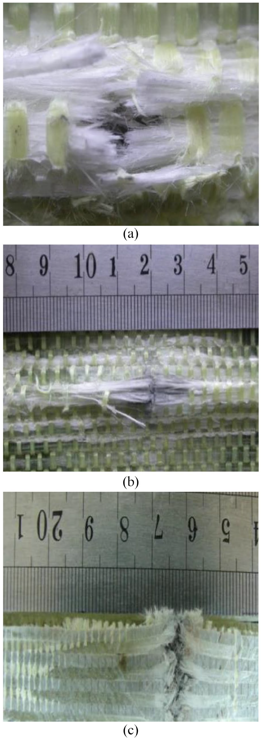
Physical view of damage to a three-dimensional woven reinforced composite: (a) damage to the filament and resin substrate at the bullet impact surface, (b) damage to the filament and resin matrix at the bullet exit surface, and (c) top view of the cross-section.
As shown in Figure 9(a) and (b), two-dimensional laminates of the same thickness made of the same fiber raw material were subjected to bullet impact damage tests. When the two-dimensional laminate received a high-speed bullet impact, delamination damage was more pronounced than when a low-velocity bullet impact occurred, that is, the so-called delamination phenomenon. Figure 8(c) also shows that the filament fracture near the impact point and the resin matrix rupture were more severe during the bullet impact, indicating that the three-dimensional woven reinforced composites were able to both reduce the shear damage between the layers and better resist the bullet shot into the composites (target). 31

Physical view of damage to laminate: (a) low velocity impact and (b) high velocity impact.
Comparison between simulated and actual observations
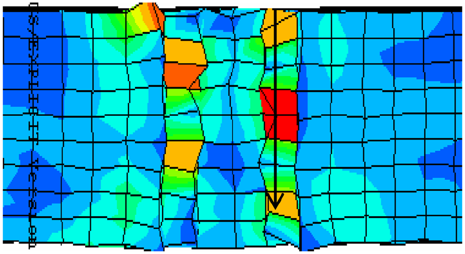
As we make finite element simulation analysis by reduced integration, there is a visible hourglass phenomenon in the simulation diagram. We ignore the hourglass in the theoretical analysis, or we can avoid the hourglass by full integration in the future research. Figure 10(a) was a top view of the final damage of the three-dimensional woven reinforced composite as simulated using finite elements. As can be seen from Figure 10(b), when the bullet impacts the three-dimensional orthogonal woven reinforced composite material at a fixed incident velocity, the damage of the incident surface and the exit surface after the finite element simulation of the bullet impacting the composite material is expressed by the lateral distance (cm). The damage distance is basically consistent with the simulated damage diagram. The yarn breakage of the composite material on the exit surface of the warhead is rougher than the incident surface, and some fibers and matrix are pulled out and cracked; there was essentially no delamination within the three-dimensional woven reinforced composite. However, delamination was more common in two-dimensional planar reinforced materials or laminate reinforced materials, an advantage that was also evident in Figure 9(b), which demonstrated the finite element simulated graphs. The actually observed damage holes were essentially a consistent match. A local enlargement of the final damage to the side after simulation of the three-dimensional woven reinforced composite under high velocity bullet impact was shown in Figure 11.

Comparison of the final damage pattern and simulation of the composite: (a) finite element calculation of ballistic impact damage pattern and (b) real damage pattern of the composite.
Enlarged view of the side after simulated impact damage.
Analysis of failure mode of target plate (composite)
The three-dimensional woven reinforced composite not only has little shear damage on the surface, but also can better resist the penetration of the bullet into the target, as shown in Figure 12. The yarn short cracks of the composite on the bullet incident surface are relatively flat, and the cracks and depressions of the matrix can be clearly seen, as shown in Figure 12(a); some fibers and the matrix are pulled out and cracked, as shown in Figure 12(b); it can be found that the stress on the incident surface and the exit surface of the composite is different through the partial magnification, and it is obvious that the incident surface is not the same. It is mainly the compression failure of the fiber and the cracking of the matrix, while the tensile failure is mainly at the exit surface, as shown in Figure 12(c).

Damage deformation diagram of target plate: (a) shearing and compressive failure and cracking of the matrix of fibers on the incident surface of bullet, (b) tensile failure of fibers and cracking of the matrix on the exit surface, and (c) ection top view of damaged composite.
It can be seen that the failure area of the three-dimensional orthogonal woven composite is relatively small, the failure also only occurs locally, and the bending deflection is relatively small. The tensile failure mainly occurs in the thickness direction. The obvious difference from laminate composites is that under high-speed impact, the overall deformation of laminate composites is large, mainly because it can’t provide greater bending stiffness and does not maintain surface-to-surface contact in the thickness direction. The coupling force, the bending deformation deflection in the thickness direction is also large, so it is easier to deform, that is, the delamination phenomenon we often see. It can be seen from Figure 12(c) that the yarn breakage and matrix cracking are very serious in the area near the impact point during the penetration process. It can be seen that the three-dimensional textile structure can not only reduce the shear damage on the surface, but also better prevent the bullet from penetrating the target plate.
Conclusion
During the propagation of the stress wave in the three-dimensional woven composite, there was first a horizontal linear segment on the stress-time graph, and the peak stress increases with the increase of the velocity of the bullet incident on the three-dimensional woven reinforced composite. The stress wave-time curve shows that the propagation of the stress wave on the material is consistent with the theoretical analysis. After the bullet passes through the incident surface of the 3D woven reinforced composite, the reinforced yarn is still relatively flat after breaking; after the bullet is shot from the lower surface of the 3D woven reinforced composite material, the fracture of the reinforced yarn is rougher than the incident upper surface, which is mainly manifested in a few. The reinforcing filaments and the resin matrix are cracked due to strong extraction. After bullet incidence, the delamination phenomenon did not occur inside the three-dimensional woven reinforced composite, and the actually observed damage holes were basically consistent with the graphs after simulation using finite element software. The final deformation failure of the composite is also in good agreement with the experimental results, which shows that the established target plate model based on the continuum can accurately and effectively simulate the ballistic penetration process of the three-dimensional orthogonal woven composite material through the single-cell model.
Footnotes
Author’s note
Fei Qian and Lei zhao are co-first authors of the article.
Declaration of conflicting interests
The author(s) declared no potential conflicts of interest with respect to the research, authorship, and/or publication of this article.
Funding
The author(s) disclosed receipt of the following financial support for the research, authorship, and/or publication of this article: The work is funded by Integration Platform of Industry and Education of Jiangsu Higher Vocational Education (Jiangsu Vocational Education 2019. No 26), the project supported by scientific research fund of Yancheng Polytechnic College (ygy2008), Jiangsu High Vocational College Academic Leaders High-end Research and Training, and Jiangsu Higher Vocational College Teachers’ Professional Leaders’ High end Training (Team Visit) Project (2022TDFX008). The work is also funded by Deeply Integrated Training Platform of Industry and Education of Jiangsu Higher Vocational Education (Jiangsu Higher Education 2016. No 19), Qing Lan Project of Jiangsu Colleges and Universities for Young Academic Leaders (Jiangsu Teachers’ letter (2020) No. 10), Jiangsu Province Higher Vocational Education High-level Major Group Construction Project-Modern Textile Technology Major Group (Grant number: Jiangsu Vocational Education 2020. No 31). Brand Major Construction Project of International Talent Training in Colleges and Universities-Modern Textile Technology Major (Grant number: Jiangsu Foreign Cooperation Exchange Education 2022. No 8) also supports the research of this subject.