
Abstract
This study presents an analysis of the possible use of a viscose rayon (CV) fiber from textile industry wastes to develop a reinforced cementitious composite as an alternative for textile discharge valorization. Several techniques were used to characterize precursor fibrous waste material such as SEM, FT-IR, DSC, and TGA. The experimental studies were conducted based on a conventional cementitious mortar (control) and four different fiber contents (0.5, 1, 2, and 4 wt%). For mechanical behavior analysis, uniaxial compressive strength tests were carried out at different ages (7, 14, and 28 days after production). The results showed favorable CV fiber addition as reinforcement up to a maximum limit. The optimum concentration of fiber was 0.5 wt% (FRC0.5), which provided 28 days of higher compression strength. The addition of CV waste as reinforcement in cementitious matrix resulted in an improved compressive strength above 20.6% compared to the conventional non-reinforced mortar. Furthermore, CV fiber addition improved the ductile behavior of the new composite allowing a controlled failure, even after maximum rupture loading.
Introduction
The textile industry has a high impact on the world economy. Textile production worldwide grew 97% in the last 10 years, international trade in textile and clothing grew by 175%. Considering the Brazilian economy, in 2017, clothing manufacturing reached US$ 45 billion and participated with 8% of the country’s gross domestic product (GDP), affirms Garcia et al. 1 It is also responsible for employing 17% of workers in the Brazilian industry. 2 Textile industry is important to different regions where it settles. Euratex 3 indicates that in the European Union, 5% of its employees work in the textile industry and 9% in other companies. Among the various materials used in textile production, cotton, polyester, viscose, and polyamide fibers, occupy the top of the list of inputs in the Brazilian sector. 4 In 2014, about 1 million tons of fabric was produced in Brazil with four types of fibers, generating approximately 170,000 t of waste, of which only 20% of the discarded material was reused and the remainder deposited in dumps and landfills.4,5 In comparison, according to United States Environmental Protection Agency (EPA), 6 the USA generated around 16 million tons of textile waste in 2015, but only 15% was recycled, while the same number indicates the recycling level of worldwide textiles. 7
The positive and negative impacts involving the textile industry can also be seen in other markets, such as the construction industry. With significant economic and social participation, this sector is responsible for using half of the natural resources, 40% of energy, and approximately 50% of global waste. 8 Nowadays, concrete is the most widely used material in civil construction. 9 It is estimated that annually, 25 billion tons of this material is consumed by the population, that is, about 3.5–3.8 t per person.10,11 In fact, concrete is characterized by it is excellent mechanical behavior and considerable durability. 12 However, it is susceptible to several problems related to deterioration, which influence the service life of structures. 13 Moreover, ordinary Portland cement, the main component of concrete, emits significant levels of CO2 in it is production,14,15 the use of mineral resources and fossil fuels for the production of steel industries, 16 as well as a high volume of demolition waste. In the European Union, 850 million tons of waste material are generated per year.17,18
One of the biggest industrial challenges is to achieve sustainable development among the most diverse sectors. The intention is to integrate economic growth, environmental protection, and social equality and to meet current needs without compromising future resources. 19 Highlighted is the focus to reduce the consumption of non-renewable resources, energy, emission of polluting gases, and reduction of water and air degradation. 20 Thus, several studies have focused their evaluations on sustainable alternatives for the construction industry, mainly in the search for innovative materials with unique properties. Fiber-reinforced composites (FRCs), both natural and manufactured, are notable options for such purposes. 21 As mentioned by Khandelwal and Rhee, 22 due to their reduced dimensions, fibers have superior mechanical resistance to those of porous matrixes. The region between the fiber surface and the matrix is called the interface, which plays a crucial role in the performance of the composite. Due to the action of external loads on the FRC, cracks pass through the matrix until reaching the interface, which distributes the load along the fiber. This, in turn, offers resistance to the extension of cracks until the “fiber pullout” occurs, which provides diffusion in the propagation of cracks, which redistributes the load through the structure. 23
Studies on different types of fibers have shown an increment in the levels of mechanical resistance of construction materials. Raw materials from natural origins, such as coconut fibers, were analyzed by Wang and Chouw. 24 The results demonstrate improvement in the compressive strength and impact resistance of concrete reinforced with coconut fibers. Similar results were found with hemp and bagasse from sugar cane, 25 curauá, and other cellulosic fibers. 26,27
Viscose Rayon (CV) is a fabricated textile material and the most commercialized fiber from cellulose pulp, 28 manufactured by chemically dissolving wood pulp. 29 As a cellulosic fiber, CV fibers possess a broad range of properties, 30 density around 1.52 g/cm³, 25–30 tenacity and 18–20 cN/tex for dry and wet fibers, respectively.31,32 Elongation up to 25% (dry) and 30% (wet) results in a high strain to failure.31,33 For comparison among cellulosic materials, the tensile strength of CV is 20%–40% lower than cotton fiber, while its elastic modulus is similar, as strain at failure for CV fibers are 8%–23.5%. 34
Studies have shown a great alternative of using CV fiber as reinforcement for composites in different areas such as construction, automotive, and medical applications.35 –37 The insertion of natural, synthetic, or residual cellulosic fibers have shown great potential, improving the mechanical properties (flexural and compressive strengths) of cementitious composites.38 –40 In addition, the use of fibrous waste contributes significantly to the sustainable development of the textile and construction industry. 41 It is important to highlighted that the CV fiber waste is not enough explored in the scientific literature, only a few studies approach this type of fiber for the reinforcement of cementitious composites materials.
This study presents the characterization of CV residues fibrous material generated by a textile industry process called raising, where it is applied to reinforced cementitious composite. A compressive strength test was also performed, where mechanical and structural behavior of a cementitious matrix composite material reinforced with different proportions of residue were analyzed.
Materials and methods
Materials
The precursor agglomerated mass of CV fibers with length varying from 5 to 15 mm and fineness of approximately 1.5 denier (g/9000 m) is sourced from waste disposal of a textile company. In particular, a material is derived from raising, one of the finishing processes for woven and knitted fabrics. The substrate passes over two cylinders covered by teasel burrs, in which, the mechanical abrasion provides fiber pullout, 42 as well as significant fiber loss from the fabric surface, discharged as waste (Figure 1). The result from this physical treatment improves the softness, hairiness, and thermal properties of textile material. 43
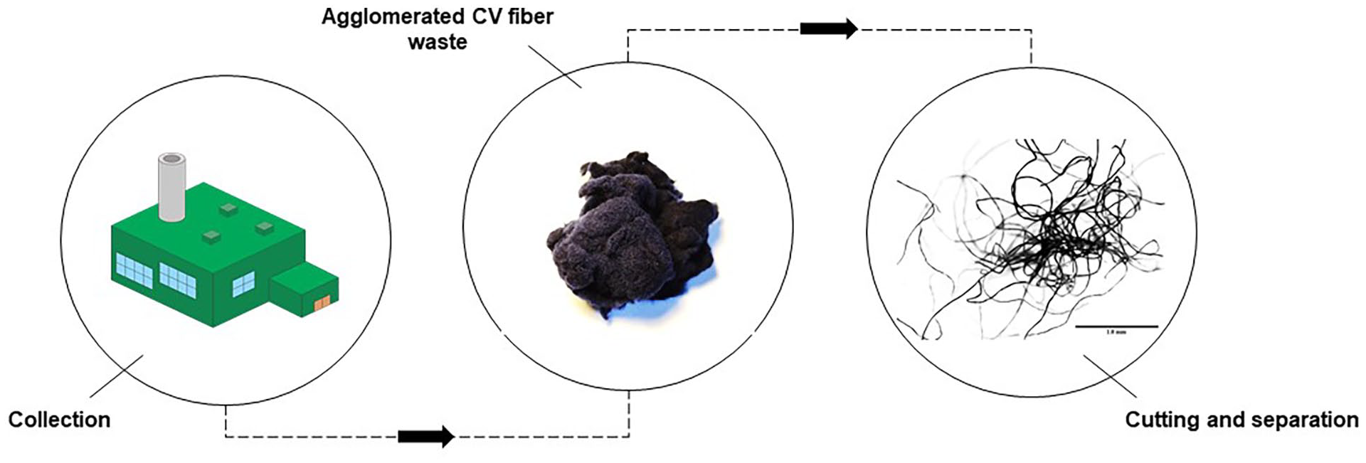
Textile waste fiber collection and preparation.
The cementitious matrix components were Portland cement CP II-E-32 (Votoran Company), sand with a uniform diameter of 2 mm, and a water/cement (w/c) ratio, as indicated by Brazilian standard NBR 7215. 44
Methods
Morphological and thermal characterization of the CV fiber
The morphological analysis of waste was performed using Scanning Electron Microscopy (SEM) by JEOL equipment, model JSM-6390LV. The sample was initially deposited in a stub and coated with gold, using the sputtering technique in a LEICA EM EMS 500 model.
To identify the type of fiber present in the waste, a Fourier Transform Infrared Spectra (FT-IR) analysis was performed in order to verify the chemical structure of organic compounds. The equipment used was NICOLET-AVATAR 360 with OMNIC 5.2 software. The spectrum was recorded at a temperature of 20°C ± 1°C, with a spectral resolution of 16.0 cm−1 and recorded of 64 scans.
Differential Scanning Calorimetry (DSC) technique was performed to investigate the thermal behavior of the material. The equipment used was METTLER TOLEDO, model DSC822, with temperatures and calorimetric responses performed with high-purity metallic standards: indium (156.6°C ± 0.2°C) and zinc (419.5°C ± 0.3°C). To maintain an inert environment, nitrogen was applied at a flow rate of 20 mL/min. The fibrous mass used was approximately 3 mg at a rate of 10°C/min.
Thermogravimetric Analysis (TGA-DTG) was carried out using a TGA 8000 Thermogravimetrc Analyzer by PERKINELMER. The temperature range of 30°C–1100°C with a heating rate 10°C/min was applied in which samples of fibrous material were tested in order to evaluate the decomposition temperature, dehydration reactions, combustion, among others. 45
Test sample preparation
The measure of mixed components was defined for five different sample groups: control sample without fiber addition and four different mass concentrations of textile fiber waste: 0.5% (FRC0.5), 1% (FRC1), 2% (FRC2), and 4% (FRC4). It is important to mention that the percentage of sand weight was partially substituted by fiber waste. The mix proportions for each composite sample are presented in Table 1.
Mix proportions of sample by weight ratio.

The mortar mixing procedure was carried out with the addition of materials following steps indicated in NBR 7215. 44 In this way, water was first added, followed by cement, mixing it using a metal stick. Gradually, the defined volume of sand was added and mixed until homogenous. It should be noted that the mortar with fiber waste was added together with Portland cement at the same stage.
It is important to mention that it was difficult to disperse the fiber mass in cement paste. Thus, 12 and 17 mL of water were added to the sample preparation with 2% and 4% of fiber reinforcement, respectively. This aspect is also commented by Lourenço et al., 46 as reported in his work on concrete reinforced with cotton and polyester fiber. In view of this, it is important to mention moisture regain. Elmogahzy and Farag 47 explain that the weight of water in a material expressed as a percentage is oven-dry weight, which defines moisture regain. This parameter directly affects adhesion between the matrix and reinforcements, as mentioned by Zhou et al., 48 in which hydrophilic natural fibers decrease the capacity of adhesion with hydrophobic polymer matrixes.
The forming of the sample was carried out in a cylindrical mold with 100 mm of height, and 50 mm of diameter, following the guidelines of Standard NBR 7215. 44 A thin layer of mineral oil on the mold walls was applied to facilitate the demoulding of the samples. For compressive strength tests, 75 samples (15 samples for each concentration of reinforcement) were prepared.
The filled mortar molds remained for 24 h at a room temperature of 21°C. Afterward, samples were demolded and immersed in a calcium oxide saturated water tank to continue the curing process until the ages of 7, 14, and 28 days. It is noteworthy that the curing of the sample is an important factor in the development of the mechanical properties of cementitious materials. 49 Samples were removed from the water tank according to the curing period established.
The mechanical characterization of the cementitious composite
The mechanical characterization of the developed composite was carried out with compressive strength tests. For this, the universal testing machine EMIC 23–100, INSTRON/EMIC, was used. The equipment was configured with a loading speed of 1 mm.min−1. The samples were removed from the saturated water tank according to previous ages established and tested while wet in the equipment for testing compressive strength, according to Standard Norm NBR 7215. 44
Results and discussion
Morphological and structural analysis of waste fibrous material
According to the industrial identification, the fibrous waste material was composed of 100% CV. Figure 2(a) and (b) presents the morphological characteristics of the waste used, where the fibrous shape can be observed. The average diameter and length of fiber were 25µm ± 5 µm and 10µm ± 5 mm, respectively.

SEM micrographs of fibrous waste with magnification (a) ×200 of tangled fibers and (b) ×2000 of strips on the fiber surface.
Note that the fibers in the waste volume are tangled (Figure 2(a)), due to the plushing stage. Suspended fibers are removed from the process by suction and when stored, they are agglomerated in the residual volume. It is known that CV fiber is obtained from the cellulose regeneration process, in which, during the self-retraction of core material, there is the formation of stripes along the entire length of the fiber, as shown in Figure 2(b), providing a substrate with a wrinkled surface. 32 The fiber geometry plays an important role in the mechanical properties of the resultant composites. Alagirusamy and Das 50 explain that fibers can present crimp, twist, fibril, and mesh in their morphological characteristics, which allows a better mechanical anchoring, because matrix fills up those spaces, resulting in strong bonding.
To proceed with material identification, an FT-IR test was performed. The results obtained can be seen in Figure 3. According to the Institute of Chemistry University of Tartu, 51 , vibrations related to CV fiber are considered broad spectral bands at 3321 and 1416 cm−1. The relative vibrations perceived through FT-IR analysis show bands between 3329 and 3294 cm−1, referring to the O-H stretch and 2900 cm−1 for C-H stretch. 52 The peak at 1427 cm−1 refers to O-C-H flexion, characteristic of manufactured fibers. 52 It is important to note that at some points of analysis, data is similar to those found in fibrous material of natural origin. However, Comnea-Stancu et al. 52 explain that a cellulosic base is a preponderant component of both man-made and natural fibers, and thus, the vibrations are similar. On the other hand, in a company manufacturing process, about 95% of the textile products originate from CV.

FT-IR absorbance spectra of fiber waste.
Thermal analysis
To investigate phenomenal events regarding physical changes in materials, three techniques were used: DSC and TGA/DTG. For the first analysis, the endothermic process was observed between 31.72°C and 121.82°C, due to the water evaporation of the sample, as shown in Figure 4. This is according to the data presented by Gurudatt and Tripathi 53 , who attributed a similar temperature range – 50°C and 100°C – to the water evaporation process in CV fibers. In the same line of reasoning as illustrated in Figure 4, the range between 286.77°C and 381.62°C corresponds to the endothermic process of material decomposition, with a temperature peak of 350.72°C. Similar data is also reported in the literature for CV fiber.54,55

DSC analysis of the fiber waste.
Figure 5 relates the results obtained by the TGA and DTG techniques. The thermal decomposition in a single cover, between the temperatures of 330°C and 390°C for the waste sample, in which there was zero residual mass at the end of the process, is showed in Figure 5. It is worth mentioning Xu et al., 56 who explain that the process starts with thermal degradation, followed by depolymerization and degradation of polymers, ending with the carbonization chain and decreasing slope curve. On the other hand, for control and FRC2, evaluated at an age of 28 days, results showed relatively similar behavior for both samples, with significant weight loss of about 15%–20% and 10%–20%, respectively.

TGA and DTG curves of CV fiber waste, control, and FRC2 specimens.
DTG curves Figure showed that composite FRC2 has two stages, but in which there is clearly no evidence of any chemical change (Figure 5). It is possible that fibers, in this case, only modify the mechanical and structural behavior. As a regenerated fiber, CV can give rise to products with excellent moisture absorption, soft and smooth touch, and breathability.57,58
Mechanical behavior of the cementitious composite
The results obtained through a compression strength test for the cementitious composite with residue (FRC’s) and control are shown in Figure 6. As shown, the resistance increased according to ages of 7–28 days. At 7 days of production, samples containing 0.5 wt% of textile residue reached greater resistance to compression, 14.03 ± 0.62 MPa. The results were promising for matrix with 0.5 wt% waste reinforcement, since studies with synthetic Nylon fibers with the same fraction achieved lowest compressive strength at 7 days of curing. 39 On the other hand, the lowest compressive strength was 6.06 ± 0.3 MPa for the sample with 4 wt% residue reinforcement. It is worth mentioning the uniformity obtained in the compression results, with variation coefficients of 4.38% and 4.62% for the samples with 0.5and 4 wt% of residues, respectively. At 14 and 28 days of curing, the data obtained attributed the highest resistance levels to FRC0.5, 16.61 ± 0.66 MPa, and 19.52 ± 0.18 MPa, respectively. The results indicate that higher concentrations of fiber do not necessarily lead to an increase in strength. The contribution of CV as reinforcement was also reported by Cornelius et al., 59 who identified an optimum quantity of fiber between 0.1 and 0.2 wt% in the concrete matrix.
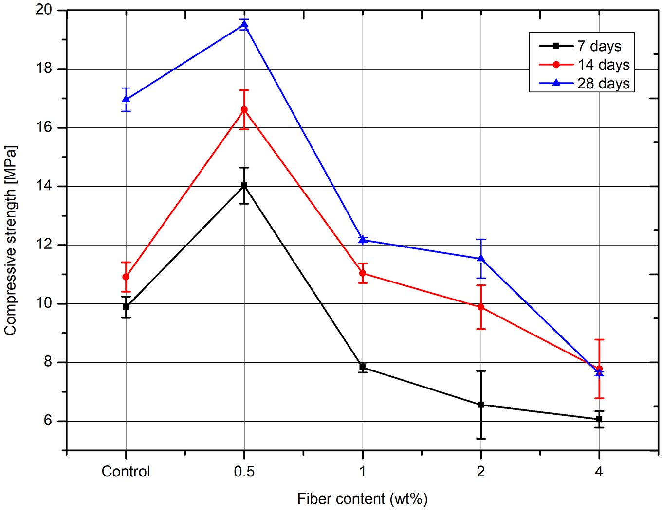
Compressive strength of samples.
Compared to studies that used natural cellulosic fibers as reinforcement of cementitious composites, the results of this study on compressive strength were lower than composites using for example jute fiber and bamboo.60,61 However, it is considered that there was a surface treatment of fibers which boosted the adhesion between matrix and fiber, which influenced the increase of mechanical properties. In addition, it is noteworthy that no treatment was performed for this study.
Chen 31 explains that the interaction of particle-particle structure within the composite is reinforced by the addition of fibers, resulting in improved strength. On the other hand, reinforcement generates a weak internal structure. With this in mind, the author mentions that, when under external compression, failure of the composite can occur before the maximum rupture load resulting from the fragile internal arrangement. 62 In addition, the material fragility may be associated with a fiber mass higher than the appropriate limit.
As mentioned by Wu, 63 fiber content above the ideal capacity can create voids containing air that can be formed during mixing. High amounts of fibers form a mixture that prevents airflow out of the material, thus causing a reduction in the mechanical properties of the composite. Following these considerations and analyzing results, is notable that a ratio above 0.5 wt% for regenerated fiber is not efficient, data obtained from experiments showed decreasing mechanical resistance to FRC1, FRC2, and FRC4. These data were also in compliance with other studies with similar textile synthetic and recycled fibers, which showed that 0.5% of fibrous reinforcement is efficient for increasing mechanical properties.39,64 On the other hand, addition above 1 wt% decreased the mechanical properties of cementitious composites reinforced with cellulose fibers as mentioned by Ghasaei et al. 65
From Figure 7, it is observed that, in fact, samples that achieved the lowest compressive strength (FRC1, FRC2, and FRC4) had black areas in their structures, representing air voids, and agglomerated fiber points. In addition, fibers distributed in the cementitious matrix were observed, with the presence of pores. Of the fibers detaching from the cementitious matrix along it is reinforcement length, few fibers presented ruptures due to the mechanical set resulting from their length immersed in a cementitious matrix.

SEM micrograph of (a) FRC1, (b) FRC2, and (c) FRC4.
The stress transfer between matrix and reinforcement in a composite is influenced by the critical length of fibers. As previously mentioned, the dimensions of fibrous material affect the strength of the composite, since if the fiber length is inferior to a critical length, the anchoring will not be efficient and likely cause fiber pullout or rupture, detaching from the matrix and not performing the expected reinforcement function, according to Silva et al. 66 The opposite also leads to a reduction in properties, that is, when the length is longer than the critical one, failure occurs due to agglomeration of fibers in the material. 66 In this sense, Matthews and Rawlings 67 define the critical length as being the minimum fiber length for a given diameter that allows fiber tension failure instead of the shear failure of the interface – defined as the shortest length necessary for the maximum development of tensions.66,68 It is important to remember that waste originates from an industrial process, so there is no uniformity among the lengths of fibers and thus it was difficult to consistently maintain the same measurement. Therefore, for the purpose of this study, the agglomerated fibers were manually separated to obtain approximately 10 mm of fiber length and disperse it randomly into the mortar. As shown in Figure 7, a small variation of fiber length may be tolerable, as it does not contribute significantly to the material’s final strength.
In this regard, it is essential to highlight the important issue of the relationship between the length and diameter of the fiber. The stress force under matrix composite is transferred to the reinforcement through the interface at a different level because it is assumed that there is a difference between the stress modulus of materials. The fiber, when aligned parallel to the loading direction, has the distributed tension felt in almost the entire area relative to its length, toward the axis, except at the end of the fiber. In this way, a large longitudinal area allows the fiber to withstand greater loads, providing superior distribution of tension along the surface. 67 This way, the possibility that fiber dimensions are not in fact uniform and not well distributed, mainly in the samples with a higher amount of fibers, can be considered. Thus, based on differences in the compression tests (decreased compressive strength from FRC0.5 to FRC4), assumptions were made related to the entanglement of precursor material. Additionally, it is important to consider the fact that a greater amount of fibers can increase the number of filaments in perpendicular positions to the direction of effort application. This may be a factor that contributes to the reduction of mechanical strength. This is because as the fiber presents itself as an aggregate of nearby filaments, with the application of the load perpendicular to its axis, there is less resistance for its separation (easier to separate them). This occurs even in cases in which coupling between fiber/cementitious matrix is suitable. In this case, we could associate the region occupied by perpendicular fibers as microcracks, acting as effective sites of stress concentrations, thus not contributing as a reinforcement element. This fact could only be disregarded under conditions of compression efforts in the region of the microstructure considered, as in this case the cracks would be closed.
As mentioned by Zhu et al., 69 the interfacial transition zone (ITZ) is critical to the comprehension of mechanical properties of cementitious composite, in which the interaction between aggregate (fiber) and the matrix is impacted by reinforcement shape. Thus, the number and perimeter of the fibers may increase the ITZ volume, which affects the compressive strength. 70 Consequentially, FRC4 samples had the highest volume of fibers, which resulted in the lowest compressive strength.
As shown in Figure 8(a) and (b), at the base, where the fibers are connected, it is notable that fiber is inside an orifice, without apparently filling in entirety. In this sense, it is important to note the effect of the difference between Poisson’s ratio of fiber and the cementitious matrix and, directly, the elastic modulus between both materials. With the tractive application of the fiber, there is a much greater transversal deformation of fiber than the matrix, which would lead to a rupture of the interface and, consequently, transfer of load to fiber. Another important factor is that CV fiber has a great moisture absorption potential, around 13%. 71 This, when preparing the composite, allows the fiber to swell and cause a reduction in its volume during the curing process (~15% at least, compared to the volumetric contraction of cement, which has a value of ~1%), which it also contributes to a reduction in fiber/cement matrix coupling. Therefore, greater amounts of added fiber would contribute to increasing stress concentration and areas with low load transfer from matrix to fiber. In this sense, choking carried out by fiber length, screwing, and friction with matrix is the main reinforcement mechanism. This can be seen in Figure 8(b), in which fiber pullout at some points as well as breaks occur through mechanical anchoring.

SEM micrograph of fibrous reinforcement 500× to (a) FR0.5 and (b) FRC4.
Moreover, Figure 8 shows SEM for FRC0.5(a) and FRC4(b), where it is possible to observe the interface of the composite after maximum load. It was observed that low content of waste reinforcement provided a better adhesion to the cementitious matrix, increasing the strength resistance of the material. On the other hand, Figure 8(b) presents the contact area between reinforcement and matrix for FRC4, where a higher distance was found compared to FRC0.5 (Figure 8(a)). Zukowski et al. 72 explain that through the curing process, the hydrating cementitious matrix could affect fiber swelling and thus increase the reinforcement volume. After this occurs, the fiber shrinks over time, which decreases bond adhesion and impacts the movement of fibrous material. In this way, the material mechanical properties are reduced.
Visual failure analysis
An important factor for assessing fractures of cementitious material is knowledge of the cracking of the sample, gained through macro-structural observation. According to Figure 9(a) to (e), it is possible to verify the failure points of the samples after exposure to the maximum breaking load. It is notable that the control sample, Figure 9(a), presented the greatest amount of damage to the structure, containing fractures as well as the detachment of considerable fractions of mass, in addition to cracks along its entire length, represented by the highlighted areas on the images.

Macrostructural failure of compressive strength of 28-day curing sample: (a) control, (b) FRC0.5, (c) FRC1, (d) FRC2, and (e) FRC4.
The addition of fibers to the cementitious matrix kept the structure aggregated, even with the formation of small faults, as shown in Figure 9(b) to (e). The fibrous material supports cracks by fiber pullout and sliding against the matrix, preventing the propagation of cracks by stabilizing and applying traction to close the crack surface. Thus, it prevents premature breakage of the structure by the increasing strength and deformation levels of the composite.73,74
For better visualization of fractures, a digital microscope and high-resolution camera were used. Figure 10 illustrates the images obtained. It is clear that FRCs, Figure 10(c) to (j), present failures smaller than the control samples, Figure 10(a) and (b), reinforcing the hypothesis that fibers increase mechanical resistance in structures. In sum, fibrous material stabilizes fractures in matrix composite after load ruptures.

Failure after compressive strength tests of samples aged 28 days: (a and b) control, (c and d) FRC0.5, (e and f) FRC1, (g and h) FRC2, and (i and j) FRC4.
Figure 10(j) shows the lack of homogeneous dispersion of fiber in the cement matrix, which may be responsible for decreasing the compression strength results. A study by Chakraborty et al. 75 explains that mortar samples prepared with jute fiber added directly into the cement slurry did not present suitable workability. It is known that this kind of fiber is hydrophilic. Consequently, during cement hydration, fibrous material requires all the available water, which affects cement workability. The same authors recommend saturating the fiber before adding it to mortar mixing for better dispersion; but even though, fiber content higher than 2 wt% was found to reduce compressive strength. However, it is important to consider that the presence of fibers improves the ductility of the material, which is positive in structural assemblies.
Conclusions
During the mortar mixing process, there was difficulty obtaining adequate consistency in the cementitious mass reinforced with waste fiber, and thereby necessary to add water. It is believed that this is caused by the high hydrophilicity of CV. Because of this, after the initial 24-h curing phase, there was a small retraction in the height of the sample, caused by the water used to hydrate the cement.
After 28 days of curing, of the different reinforcement mass ratio inserted, FRC0.5 was the best result obtained for adding fibrous waste. The importance of the extension of the inserted fibers as reinforcement is also emphasized, as its length and diameter are important factors that can affect the desirable characteristics of the compound.
A visual evaluation of the samples after the compressive strength tests were concluded showed satisfactory results for the insertion of fibers when considering the cracks that were generated in the material. The FRC0.5 and FRC2 samples, which in addition to being more resistant to compression, also showed the least number of cracks in their surfaces, demonstrating the ability of the fibers to hold the cemented matrix aggregated, preventing the propagation of failures.
The importance of the topic discussed in this study is emphasized based on the value of a textile residue to the production of building materials necessary to achieve civil construction with superior mechanical performance. There are advantages of using waste fiber such as low cost and decreasing areas of landfills that receive waste deposits from the textile industry. It is also an alternative construction material, as fiber reinforcement contributes toward improving mortar properties and reducing the fragility of structures under load. There is a synergy between the areas of textile and civil engineering in the search for sustainable alternatives. Furthermore, waste disposal is undoubtedly a relevant aspect that must be considered when developing solutions for society.
Finally, it is suggested that the use of CV fibers waste in cement composites should be more investigated. Flexural strength, toughness, fracture mode, other tests, and analyzes could be auxiliary in comprehension of proposed material. Also, the investigation of superficial treatment of CV fiber waste could be considered to improve adhesion bond between matrix-reinforcement for increment mechanical properties.
Footnotes
Acknowledgements
The authors wish to acknowledge the Support of Research and Innovation Foundation of Santa Catarina (FAPESC) and Capes Foundation, Ministry of Education of Brazil (CAPES) for their financial support to this study.
Declaration of Conflicting Interests
The author(s) declared no potential conflicts of interest with respect to the research, authorship, and/or publication of this article.
Funding
The author(s) disclosed receipt of the following financial support for the research, authorship, and/or publication of this article: This work was supported by the Support of Research and Innovation Foundation of Santa Catarina (FAPESC) and Capes Foundation, Ministry of Education of Brazil (CAPES).