
Abstract
This paper presents an investigation into the effect of particle size of fumed silica on the puncture resistance of fabric impregnated with shear thickening fluid (STF). Two different types of STF were fabricated from fumed silica nanoparticles with particle sizes of 12 and 40 nm respectively. The effects of the particle size and weight fraction of the fumed silica on the rheological property were studied. STFs impregnated woven fabrics were fabricated and tested for stabbing resistance. STFs made of fumed silica with large particle size have better shear thickening effect. The stabbing resistant performance of STF impregnated fabrics improved notably with the same number of layers of fabric, and STFs impregnated fabric panels also outperform the untreated fabric panels with the same areal density. The results indicated that STFs made of fumed silica with larger particle size is able to fabricate a lighter soft body armor with higher stabbing protection.
Introduction
Body armor had been designed to protect human body against various threats since the era of cold weapons. Rigid body armors with pieces of metals provide excellent protection to stab threat. However, the high weight and rigidity of this armor have also constrained the mobility of the wearer. Thus, high performance fabrics are widely utilized in body armor due to high strength and lower weight.1,2 To ensure the protecting effect, conventional fabric armors are invariably comprised of 20–50 layers of fabrics. This kind of armor is also inflexible and bulky. Therefore, a new generation body armor with higher flexible and lighter weight is becoming one of the research focuses.
Shear thickening fluid (STF) provides significant benefits for eliminating fabric layers in body armor. Lee et al. 3 investigated the energy absorption of silica based STF treated Kevlar fabric. The previous study indicated that the four layers STF/Kevlar composites have the same ballistic resistance as 10 layers neat fabrics. STF is a non-Newton fluid, whose viscosity can increase sharply under critical shear rate. It can change from liquid to solid state when under an impact, and return to the liquid state again after loading removed.4,5 This property makes STF as a smart material suitable for protective equipment. 6 There are many kinds of STF solutions composed of nano-particles and medium. The commonly used nano-particles includes Corn starch,4,5,7 PMMA, 8 CaCO3, 9 SiO2, etc.
The silica-based STFs were widely used in body armor due to high hardness and good shear thickening effect. Kalman et al. 8 investigated the role of particle hardness using hard silica and softer PMMA particles in PEG medium. According to this study, the silica materials performed better in puncture resistance than that of PMMA material. Gürgen and Yıldız 10 used various micron-sized harder SiC particles in the silica based STFs. The multi-phase STF treated fabrics have higher stab resistance. Xu et al. 11 investigated the stabbing resistance of STF impregnated soft ballistic body armor. Two kinds of silica nanoparticle with sizes of 12 and 650 nm were used in STF preparation. The STFs having larger nanoparticle size and higher weight fraction resulted in better stab resistant performance.
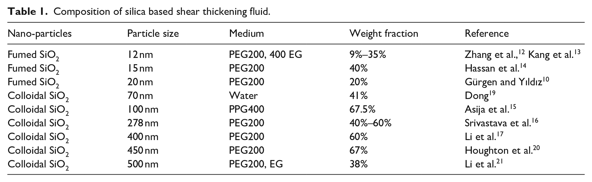
Commonly used silica nanoparticles and mediums in STFs for stab resistance are listed in Table 1. The silica particles are usually produced through the fumed and wet-chemical processes. The particle sizes of the fumed silicas are about 8–40 nm. By contrast, the particle sizes of the colloidal silicas are larger than that of the fumed silicas. The particle size of nano-particles influences the rheological behavior of STFs have been proved by many researchers. 6 The mass fraction of the fumed silica based STFs are within the range of 9%–40%.12–14 However, the mass fraction of the colloidal silica needs almost twice amount to get the same shear thickening effect.15–17 The fumed silica based STFs exhibit rapid thickening in comparison to colloidal based STFs. 18 Therefore, the fumed silica based STFs have the potential to produce lighter stabbing resistance body armor.
Composition of silica based shear thickening fluid.
Although some studies have been reported on the rheological property and stabbing performance of silica based STF, the influence of the particle size and the morphology of the fumed silica on the puncture resistance still have not been well understood. In this study, we used fumed silica with different particle sizes to disperse into PEG to fabricate STF with different weight fractions. The effect of particle size and weight fraction on the rheological properties have been investigated, in order to provide some insights into the response of STFs. Twaron® fabrics are impregnated with different types of STFs. The fabric panels were subjected to a stabbing test by using a drop weight tester mounted with a spike. Different particle size and weight fraction of silica were attempted to observe the influence on the puncture resistance. It was expected to provide new experience for designing the flexible and lightweight stabbing resistance body armor with STF impregnated.
Experiments and materials
Materials and preparation
Preparation of shear thickening fluids
The STF dispersions used in this work were prepared by dispersing the fumed SiO2 in Polyethylene Glycol (PEG). PEG was chosen as a solvent due to its low volatility and non-toxicity. PEG has different molecular weight, such as PEG200, PEG400, and so on. PEG200 with the lowest viscosity was chose for production of STFs. Two kinds of fumed silica nanoparticles (AEROSIL® 200 and OX50, supplied by Evonik) were used for STF preparation. The primary particle sizes of AEROSIL® 200 and OX50 are 12 and 40 nm, respectively.
A high speed homogenizer was used to stir the solution with the speed of 1000 rpm. The silica powders were added into the PEG200 with small amounts every times. Ultrasonic wave vibration was used to improve the SiO2 dispersion uniformity. The STFs were placed in vacuum chamber at 80°C for 1 h to remove the air bubbles in STF. Four types of STF were produced with different silica weight fractions, 15%, 20%, 25%, and 30%.
Woven fabric
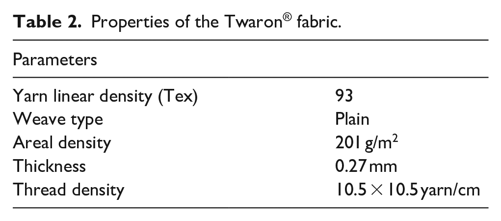
In this research, a para-aramid (Twaron®) filament yarn provided by Teijin was used to produce the woven fabric, the fabric specifications are described in Table 2. The specimens were cut in square with dimensions of 190 × 190 mm.
Properties of the Twaron® fabric.
Preparation of Twaron®-STF composites
In order to impregnate the Twaron® fabric with STF, the STF must be diluted with ethanol due to its high viscosity. The STF were diluted with ethanol at 1:1 vol ratio. The fabrics were immersed in the diluted solution for 3 min, and then squeezed by two rollers to rid the excessive STF. The impregnated fabrics were placed in the oven at 80°C for 1 h to evaporate the ethanol in STF.
The STF add-on% weight ration can be calculated using the following expression to express the actual amount of STF present on the treated fabric. The STF add-on% was

The STF add-on% in this work was optimized to be 100% to ensure that the STF was continuous and the fabrics were fully impregnated. The morphologies of the STF impregnated Twaron® fabrics were characterized by SEM as shown in Figure 1. The results from Figure 1(a) indicated that STF had uniformly impregnated the yarns and fulfilled the gap between the filaments. Figure 1(b) shown that a large number of SiO2 aggregates have been distributed on the surface of the Twaron® filaments.

SEM images of STF impregnated fabrics: (a) fabric and (b) filaments.
Experimental measurements
Rheological tests
The rheological tests of STFs were done by using a stress-controlled rheometer AR-G2 (TA Instruments-Waters LLC). A parallel-plate with the diameter of 20 mm was used to measure all STF dispersions. The gap interval of two plates was set to 1 mm in all tests to eliminate the effect of the gap size. The temperature was controlled at 25°C. In this study, the steady-state stain rate sweeps were conducted to study the rheological properties of the STFs. The shear rate was increased from 0.1 to 1000 s−1.
Yarn pull-out test
In order to investigate the influence of STF impregnated on the inter-yarn friction, the yarn pull-out test were carried out. Instron 3344 Tensile and Compression Tester was used to do the single yarn pull-out test. All tested fabric specimens were cut into the size of 120 × 200 mm. Transverse yarns were manually removed from the top edge of the fabric to create free lead longitudinal yarns of 100 mm length. The remaining fabric was clamped in a special fabric fixture as shown in Figure 2. During the yarn pull-out test, the top lead yarn was loaded via the upper grip of the tensile tester. A speed of 100 mm/min was used for pulling out the yarns until the yarn was completely removed from the fabric.

The holding fixture for yarn pull-out test.
Puncture testing
The puncture tests have followed NIJ standard 0115.0 for testing stab resistance of body armor accordingly to evaluate the puncture resistance of the samples. The standard focused on the penetrated layers of fabric which was used as the criteria for judging the stab resistance properties. In this study, we have used Instron Dynatup 8200 drop weight tester mounted with a load cell and a spike as demonstrated in Figure 3. In order to collect the dynamic resistance force from the load cell, the fabric samples were kept between two plate holders without the multi-layer foam backing materials, and the rest part of the experiments have followed the NIJ standard. The spike was mounted to the crosshead, and the total mass is 5 kg. The crosshead dropped freely from a fixed velocity of 1.5 m/s to impact the target. The fabric samples were kept between two plate holders with the inner diameter of 70 mm as shown in Figure 3. The stab targets were placed on a fabric fixture without multi-layer foam backing. Therefore, the dynamic resistance force of the neat targets can be monitored and recorded by the load cell. The energy absorption of neat targets during the penetration can be calculated from the initial velocity and penetration depth.

Dynamic impact testing setup.
Results and discussions
Rheological property of STF
The typical steady rheological responses of the two types of STFs made from 12 and 40 nm silica with weight fraction of 15%, 20%, 25%, and 30% are shown in Figure 4. Slight shear thinning was observed in both samples made from 12 and 40 nm silica at low shear rate. At a critical shear rate, the STFs demonstrated a sharp viscosity increase, which is a typical shear-thickening phenomenon. In the case of the STF with 30% of 40 nm silica particles as shown in Figure 4(b), the viscosity increased from 5.4 to 1136 Pa s after the shear rate of 10 s−1. The STFs transformed from a liquid dispersion into a material with solid-like state. As the shear rate increases, the hydrodynamic loads increase until overcoming the inter-particle loads and then the particle clusters were formed. 22 The hydro-clustered state is reversible. The STF returns to the original liquid state when the stress disappears.

The viscosity versus shear rate curve of STFs with different particle weight fraction: (a) STF with 12 nm silica and (b) STF with 40 nm silica.
Fumed silica is a non-crystalline, fine-grain, low density, and high surface area silica, which is manufactured in a continuous flame hydrolysis of silicon tetrachloride (SiCl4). The smallest components of silica called the primary particles, which are connected to one another due to mutual collision. The primary particles merge to form secondary particles called aggregate with a chain-like structure. Several aggregates can hold together to form an agglomerate, which is a three-dimensional structure. The process is demonstrated in Figure 5(a). The micro-structure of the fumed silica and the colloidal spherical silica are shown in Figure 5(b) and (c) respectively. The fumed silica has complex chainlike and branched structure resulting in high surface area, which is different from the colloidal spherical silica as shown in SEM images. 23

(a) Diagram illustrating of particle genesis in the flame, (b) SEM image of a single fumed silica aggregate, 23 and (c) SEM image of spherical silica.
The commonly accepted thickening mechanism is the hydro-cluster theory. The particles are randomly suspended in a liquid medium at equilibrium state. Beyond a critical shear rate, the layered structures disorder and hydro-cluster would be formed, which has been proved by Cheng et al. 24 The chainlike, branched structure of the fumed silica is similar to the hydro-cluster of thickening STF. The structure of fumed silica aggregates contribute to the shear thickening effect of STF. Therefore, the fumed silica based STF can get the thickening effect at lower mass fractions by comparing with the colloidal silica based STF.
Effects of the particle size on the initial viscosity
The initial viscosity of various STFs are shown in Figure 6. The initial viscosity of suspensions increases as particle weight fraction increase in the two different categories of STFs. The mechanism can be explained by the increased concentration of silica particles in the suspension, thereby strengthened the inter-particle adhesion. 25 The force networks formed by particles are increasingly constrained, and therefore the initial viscosity increases. 26

The initial viscosity of STF with different particle weight fraction.
The initial viscosity of STFs made from 12 nm silica are higher than STFs made from 40 nm silica at the same weight fraction. It is shown that initial viscosity of STFs decreases as the particle size increases. The explanation is that finer particles have more particles with defined weight fraction. Therefore, more force networks between silica particles would be formed. Finer particles are more effective to increase the initial viscosity. This is also reflected in the STF preparation process. The 12 nm silica particles needs more time to disperse uniformly.
Effects of the particle size on the critical shear rate
Figure 7 illustrated the effect of particle size and weight fraction on the critical shear rate. The critical shear rate of STFs is the shear rate that triggers the shear thickening effect which would decrease with the increase of the silica weight fraction. The critical shear rate of STFs with 40 nm silica with 15% weight fraction is 94.9 s−1, and would decrease to 10 s−1 at 30% weight fraction. The STFs made of 12 nm silica showed the same trend. The increase of the weight fraction or volume fraction of the silica particles will lead to decrease of the critical shear rate which is because of the higher silica volume fraction in the medium means higher weight fraction, thereby sufficient number of silica in the medium would form hydro-clusters even if shear rate is at lower levels. 27

The critical shear rate of STF with different particle weight fraction.
The results indicated that particle size have significant influence on the critical shear rate. The critical shear rate of 40 nm STFs with different weight fractions are between 10 and 94.9 s−1, and the 12 nm STFs are between 93.8 and 148.7 s−1, and the critical shear rate would decrease with the increase of the particle sizes. The shear thickening effect occurs at lower critical shear rates for STFs with larger particle size which has a good agreement with the rheological results reported by Lee et al. 28 The hydro-clusters approach in recent investigations suggested that the contact forces among the silica particles would form a network in the suspension. 29 Therefore, the silica particles with bigger size were found more easily to contact with each other, thereby inducing the lower critical shear rate.
Effects of the particle size on the thickening ratio
In order to compare the shear thickening behavior of various STFs, the thickening ratio (TR) is defined in equation (2) to indicate the intensity of the thickening behavior. 27
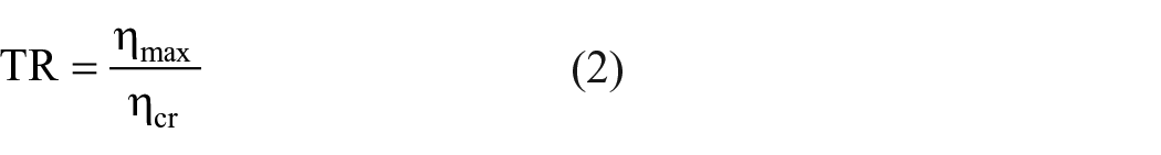
Where ηmax is the maximum viscosity of STF, and ηcr stands for the viscosity of STF at the critical shear rate.
As shown in Figure 8, the thickening ratios of STFs are influenced by silica weight fraction. The thickening ratios of STFs with 40 nm silica increased with the increase of the silica weight fraction, and would have a sharp increase beyond the 20% weight fractions. The thickening ratios of STFs with 12 nm silica increased with the increase of the silica weight fraction below 25%, and decreased from the 25%–30% weight fractions. The thickening ratio of STFs is also influenced by particle size. The thickening ratio of STFs with 40 nm is higher than that of 12 nm at higher weight fractions from 25% to 30%.

The thickening ratios of STF with different particle weight fraction.
Inter-yarn friction of fabrics
The yarn pull-out test results of 30% STF with 40 nm SiO2 treated fabric are shown in Figure 9. The maximum pulling force of treated fabric and neat fabric are 2.87 and 1.78 N respectively. When the single yarn was pulled out, the maximum pulling force of the impregnated fabric is 1.61 times higher than that of the neat fabric.

Load versus distance curves of yarn pull-out test.
The shear rate can be calculated by dividing the pull-out speed v by the distance of two yarns L shown in Figure 10. 28 The shear rate is 1.78 s−1 when the yarn pulled out at 100 mm/min. The STF is in the shear thinning stage at this shear rate, but the pull-out load is still significantly enhanced. Therefore, the inter-yarn friction enhanced by STF impregnated. Similar conclusion was drawn by Lee and Kim, 30 who stated that inter-yarn friction coefficient of the Kevlar fabrics increased approximately twice after impregnating the STF at low pull-out velocity. It is possible to mention that the silica nano-particles located in between the fibers by the impregnation, which cause a pre-strained texture in the fabrics. Interlocking of the fibers is increased due to the silica particles intercalated between the fibers and yarns. Therefore, large pull-out forces are required to overcome the inter-yarn friction in the STF impregnated fabrics.

Schematic of yarn pull-out shear rate.
Puncture resistance of fabrics
Influence of STF impregnation
In order to investigate the effectiveness of STF impregnation, 10 layers of neat fabrics target and STF impregnated target were constructed. Ten-layers fabric targets were impregnated with STF made from 12 and 40 nm silica particles with different weight fraction. Stabbing tests of spike impactor were carried out with these targets, and the target performance was indicated by the maximum impact load and total energy absorption. Figure 11 has shown the puncture resistance of the neat target and STF of 30% weight fraction impregnated target against the spike impactor. Typical load-deflection curves during the impact process were used to compare the stab resistance properties. The impact process can be divided into three stages. At the first stage, the tip of the spike contacts with the surface of the fabric and the load increases sharply. Then, the spike penetrates the fabric and separates the fibers of yarn. This is called “windowing effect.” The load oscillates during the penetration process and decrease with deflection. The third stage is that the spike passes through the fabric, and the rob of the spike interacts with surround fibers. The load increases linearly with deflection, which is due to increasing diameter of spike. It is evident in Figure 11 that the impregnation of STF enhanced the puncture resistance regardless particle size. The loads of STF impregnated fabric in each stage are much higher than neat fabrics. The increase of load attributed to the hardening effect of STF during the impact process. It has been proved that the fiber mobility is restricted by STF treatments in the yarn pull-out test. Gürgen and Kuşhan 18 have proved that the coefficient of fiction between fabric and spike was increased by STF impregnation. The windowing effect is diminished by the impregnation of STF which restricts the fiber mobility. Therefore, the load of STF treated target increased significantly.

Effectiveness of STF impregnated fabric: (a) load versus deflection curves and (b) energy absorption versus deflection curves.
The energy absorption is illustrated in Figure 11(b). The total energy absorptions of STFs impregnated fabrics are about three times higher than the neat target. The untreated fabrics have lower inter-yarn frictions. The spike penetrates through fabric easily and the adjacent fibers contribute little to the energy absorption. Therefore, the impact energy accumulated on a very local point. The energy absorption is enhanced in the STF impregnated fabrics due to the high inter-yarn frictions and the yarn-spike friction. At the same time, the spike penetration depths for the impregnated fabric are less than the untreated fabric.
Reduction of the fabric layers
The weight and flexibility are important criteria in soft body armor, thus maximum load and energy absorption of targets with same area density are considered. The area density of untreated target with 20 layers is 2010 g/m2, which is same to the STF impregnated target with 10 layers.
It is clear from Figure 12 that for stabbing targets with the same areal density, the STF impregnated targets demonstrated superior performance over the untreated targets in terms of the maximum load and the total energy absorption, which indicated that the STF impregnation could help to achieve improved stabbing resistance performance with less fabric layers. The 10-layer impregnated targets demonstrated at least 26.7% increase in maximum load and at least 63.3% enhancement in total energy absorption than the 20-layer untreated target. Therefore, better stab resistant performance with less-layer targets can be achieved by the impregnation of STF. Moreover, the 10-layer treated fabric is more flexible by comparing with the 20-layer neat fabrics that had been proved by many researchers.3,18
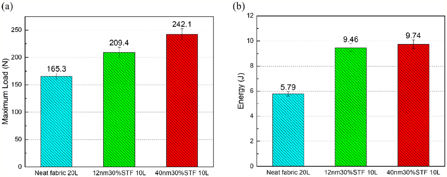
Performance of fabric with same area density: (a) maximum load and (b) energy absorption.
Influence of the particle size on the puncture resistance
From the rheological test result, it was found that STF with larger particle size related to lower critical shear rate and higher thickening ratio. Figure 13(a) compares the maximum load of targets treated by STFs made from 12 and 40 nm silica particles with weight fraction of 20%, 25%, and 30%. All of the targets were composed of 10 layers fabrics. The maximum loads of targets treated by STF with 40 nm silica are higher than 12 nm STF at each weight fractions. Therefore, STF with larger particle size have better stab resistant performance, which had a good agreement with the results reported by Gürgen and Kuşhan 18 that indicated the stab resistance is not directly related to the thickening behavior of STFs. The coarser and harder particles in STF can improve the stab resistance. The silica of 12 nm has a chainlike and branched structure. However, the silica of 40 nm is a larger spherical particle, which is coarser and harder than that of 12 nm silica. At the same time, STFs with 40 nm silica have the lower initial viscosity and higher thickening ratio than STFs of 12 nm. The lower initial viscosity leads to more STFs were distributed between the filaments. Therefore, under the impact, more silica particles in STF would gather together quickly and the spike could hardly push the fiber bundles away, which helps to improve the stabbing performance. 31

Effect of the particle size on puncture resistance: (a) maximum load and (b) SEA of fabrics.
The specific energy absorption (SEA) capacity of the neat and impregnated fabrics with different particle size are given in Figure 13(b). The SEA capacity was calculated by dividing the impact energy by the areal density. The SEA of STF treated fabrics increased by at least 106% at the weight fraction of 30%.The STF with 40 nm silica treated fabric has higher SEA than the12 nm STF. In the light of this, STF made from fumed silica with bigger particle size is the most effective mixture to obtain the lightest protective fabrics under external stabbing.
Conclusions
In this study, two types of fumed silica nanoparticle with particle size of 12 and 40 nm were used to fabricated STF with different weight fractions. The rheological property of STFs was investigated. Different types of STF impregnated fabric and untreated fabric with same areal density and same layers were prepared. Stabbing tests were carried out on Instron Dynatup 8200 drop weight tester. Yarn pull-out test was carried out to explain the mechanism of the puncture resistance of STF impregnated fabrics.
The results indicated that STFs with 40 nm silica have higher thickening ratio compared to STFs with 12 nm silica, and the larger particle size also contributes to the reduction of the initial viscosity and critical shear rate. It was also found that fully impregnated fabric with STFs having larger nanoparticle size resulted in better stab resistant performance in terms of maximum load and total energy absorption. The total energy absorptions of 10-layer STF impregnated fabrics are about three times higher than the 10-layer neat fabrics, and over 63.3% improvement in total energy absorption compared with the 20-layer neat fabrics. On the basis of the same areal density, the impregnated 10-layer fabric panels outperformed the 20-layer untreated fabric panels.
The increase of the stab resistance of the impregnated fabrics with larger particles size of STFs could be caused by the increasement of the inter-yarn friction of the fabrics as the 40 nm silica is coarser and harder compared with the 12 nm silica, which is consistent with the previous studies. The inter-yarn frictions can help to limit the movement in the fiber bundles. All of the results and findings have indicated that the fumed silica fabricated STF with large particle size impregnated fabric can help to achieve a flexible and light body armor with better stab resistance. However, the relevance between the rheological property and the puncture resistance still needs to be further studied.
Footnotes
Data availability
The data that have been collected and analyzed for supporting the findings of this study are available from the corresponding author upon request.
Declaration of conflicting interests
The author(s) declared no potential conflicts of interest with respect to the research, authorship, and/or publication of this article.
Funding
The author(s) disclosed receipt of the following financial support for the research, authorship, and/or publication of this article: This work was partially supported by the National Natural Science Foundation of China (Grant Number 11502230). One of the authors (Z Lu) acknowledges support from the University of Manchester, UK.