
Abstract
Yarns of fiber assemblies such as ropes would abrade with each other during repeated stretching or bending. The yarn on yarn abrasion failure is a main reason for the final assembly failure as the result of the relative movement to each other. To explore the influencing factors and failure mechanism, this work, taking the Ultra High Molecular Weight Polyethylene Fiber (UHMWPE) as the research object, discussed the influences of abrading frequency and the yarn tension on its abrasion life. Based on the observation and analysis of the rising temperatures from abrasion, the abrasion fragments, and morphology of failed yarns, the heating failure and crack propagation mechanisms were proposed, which provide insights into a variety of UHMWPE product designs and applications.
Introduction
As offshore exploration expands, especially in the deep sea, lighter weight becomes a critical requirement. In shallow water, people have moored to position the drilling platform on the seafloor using steel cables and anchor chains. However, when the depth exceeds 1500 m, metal structures such as steel cables and anchor chains may become too heavy and can be pulled off by their weight. Under these conditions, the lighter fiber ropes, especially high-performance fiber ropes for their superior specific strengths, become a better alternative. Compared with steel cables, fiber ropes have obvious advantages in marine engineering applications.1,2 In terms of density, the density of ultrahigh molecular weight polyethylene fiber (UHMWPE) is about 0.97 g/cm3, while the density of steel is about 7.8 g/cm3, seven to eight times that of UHMWPE fiber. The significant lightweight advantage makes the offshore mooring system lighter, and greatly reduces the installation and operation cost, and increases safety. A UHMWPE fiber rope can be stronger than a steel cable of the same diameter, therefore can be a direct replacement of steel cables in many applications. Other benefits such as superior corrosion resistance and flexibility further accelerated the adaption rate of fiber rope replacing steel cable in recent years. 3
The fiber rope, however, as an alternative to steel wire rope, like many other new technologies, suffers from a disadvantage of shorter usage history. The stability and reliability of its performance are still the main reasons to limit the replacement of steel wire rope. People are still accumulating information and knowledge concerning factors affecting the rope’s behavior and a conclusive understanding of its failure mechanism. At present, a lot of work has been done on tensile fatigue4–8 and bending fatigue9–13 of fiber ropes. In the marine environment, waves and currents occur all the time. These fluctuations lead to the periodic fluctuation of the tension on the fiber rope. Periodic tension causes the strands and fiber bundles to abrade against each other. These relative frictions can be divided into three categories, one is a relative slip, another is a relative rotation and the other is the combination of the two, as shown in Figure 1. These repeated frictions degrade the fiber and eventually leads to the failure of the rope when the tension exceeds the residual strength from the degradation rope. Therefore, it’s important to understand how fiber fiction and abrasion affect the strength and life of the fiber rope.

Fiber ropes in different applications and their deformation forms: (a) mooring ropes and towing lines, (b) two kinds of deformation form, and (c) two kinds of friction types.
Frictional fatigue of fibers is an important aspect of fiber performance that has attracted the attention of scholars for years. Some scholars developed different methods to determine the coefficient of friction. Howell 9 designed two methods to measure the coefficient of friction between fibers. Guthrie and Oliver 10 conducted inter-fiber friction experiments on viscose rayon fibers using the stick-slip technique. Rossettos and Godfrey 13 used the correlation between fiber slip as a function of the number of turns per meter in yarn to characterize inter-fiber friction. Zurek and Frydrych 11 presented a new device for measuring yarn-to-yarn friction in both vertical and skewed arrangements for six kinds of yarn. As to the frictional behavior, some scholars focused on the affecting parameters such as the compressing force or the frictional frequency, etc. Rossettos and Godfrey 13 studied the influence of the variable friction shear force distribution along with a sliding broken fiber on the Stress Concentration factor (SCF). Cornelissen et al.14,15 measured frictional behavior of aramid, carbon, and E-glass tows, both in tow-metal and tow–tow contact. Chakladar et al. 16 studied the mesoscale friction behavior of carbon fibers. Alirezazadeh et al. 17 investigated the effect of fiber fineness on the frictional behavior of polypropylene fibers using a high-precision experimental setup Tourlonias and Bueno 18 simulated the weaving motion of yarn-induced friction by varying the experimental parameters, including initial normal load, oscillation frequency, and oscillation angle.Ning et al. 19 explored the effect of coating on the yarn on yarn abrasion performances. Lots of work20–25 related to the abrasion performances mainly focused on the fabric or composites performance. For the frictional fatigue mechanism, most of the work focused on the abrasion fatigue failure of fiber-reinforced composites, a few paid attention to the fiber frictional fatigue failure mechanism. Xie et al. 26 studied the variability of the braided cord and mentioned the failure mechanism as the abrasive action. So far, few studies have been conducted on the yarn friction fatigue failure process, which needs to be further explored.
Experimental
Material
The untwisted UHMWPE yarn sample used in this study Spectras®-1000 from Honeywell, which is denoted as UHMWPE-S in this paper, with basic properties shown in Table 1.
Main parameters of UHMWPE-S.

To remove the lubricating components from the sample surface, the samples were soaked in alcohol for 2 h and then placed in standard constant temperature and humidity conditions (temperature: 20 ± 2℃, humidity: 65 ± 2%) for 48 h for pre-humidification, followed by various tests on the yarn under the same temperature and humidity conditions.
Yarn on yarn abrasion testing equipment
Figure 2(a) shows the yarn on yarn abrasion testing equipment used in this study. The equipment complies with ASTM D6611-16 – Standard Test Method for Wet and Dry Yarn-on-Yarn Abrasion Resistance. 22 A length of yarn is interwrapped in contact with itself between three rollers. A weight is attached to one end of the yarn to apply a prescribed tension. The other end is drawn back and forth through a stroke at a defined speed until the yarn fails due to abrasion upon itself within the interwrapped region. As shown in Figure 2(c), the abrasion region is divided into a double abrasion region (abrasion twice during each cycle) and two single abrasion regions (abrasion once during each cycle)
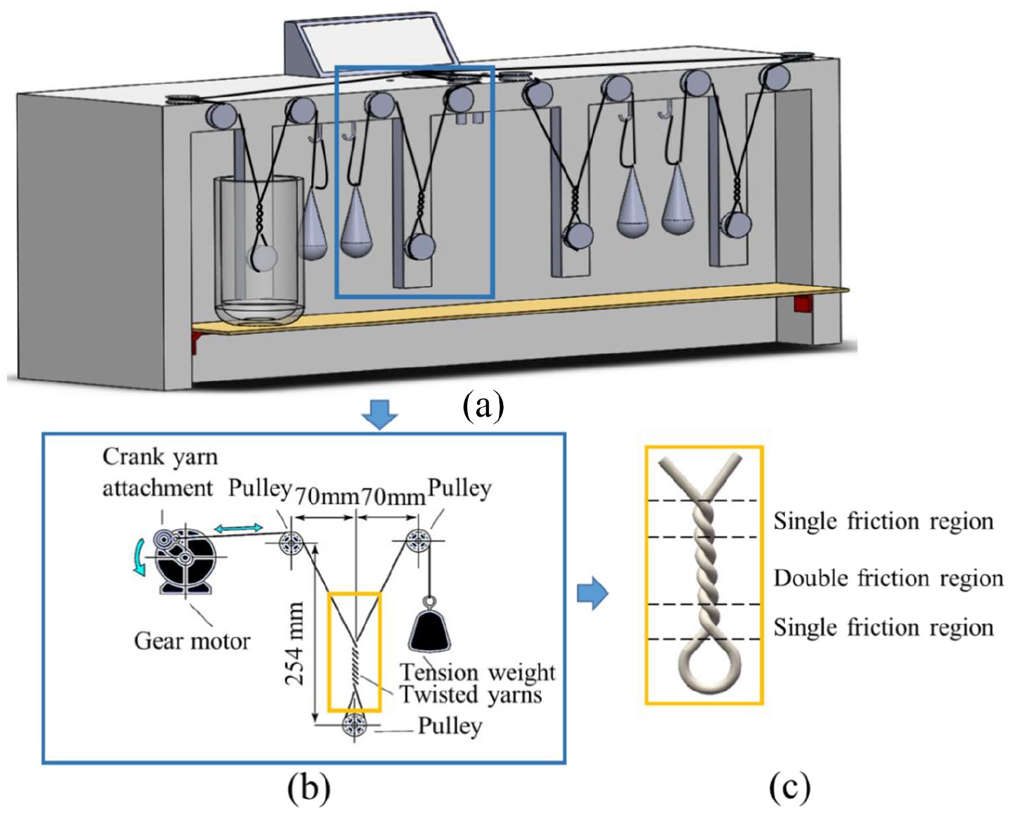
Yarn-on-yarn abrasion testing equipment: (a) overall structure, (b) experimental schematic, and (c) classification of abrasion zones.
Experiments
Two factors – abrasion frequency, and pretension on the yarns, were selected as the testing variables in this study, to investigate how these parameters influence the abrasion life, as shown in Table 2.
Experimental parameters.

The experiments were conducted at abrasion frequencies from 0.25 to 1.75 Hz with an interval of 0.25 Hz between two adjacent frequencies, under applied tensions of 25, 35, 45, and 60 mN/tex. The number of abrasion cycles to failure was recorded as the measurement of the frictional behavior of the samples.
Results and discussion
Wear during yarn-on-yarn abrasion
The wear of the fibers was the most evident form of visible damage during yarn-on-yarn abrasion. Figure 3 shows the typical pattern of the abrasion area after several abrasion cycles at an abrasion frequency, in this case, in 0.5 Hz with an applied tension of 35 mN/tex. Before the testing, the fiber bundle surface without abrasion is relatively smooth and free of hairiness, as shown in Figure 3(a) and (f). As the abrasion started, broken fibers begin to show to form hairiness and gather on the ends of the abrasion regions, as shown in Figure 3(b) and (g). As the tests advanced, lots of hairiness gathered on the end of abrasion regions to form fibrous knots, as shown in As the friction continues, the double friction region hairiness feathers gradually increase, and the resulting hairiness, broken head in the repeated scraping action, to the single friction region to gather, and show the phenomenon of fiber nodules, as shown in Figure 3(d) and (j). In this process, the individual fibers within the yarns in the double-abrasion region continued to break, the fiber amount gradually decreased and the yarn became thinner. Eventually, the whole fiber yarn broke at the weakest point, as shown in Figure 3(k). The fiber broken end showed a tapered shape, indicating that the fracture of the fiber occurred gradually. At the same time, a small number of filament bundles existed at the end of the tip, indicating that the final stage of fracture contained the fiber pulling action.

Surface condition of abrasion regions under different abrasion cycles: (a) 0 cycles, (b) 500 cycles, (c) 1000 cycles, (d) 1500, (e) SEM image of debris, (f) 0 cycles, (g) 500 cycles, (h) 1000 cycles, (i) 1500 cycles, (j) 2000 cycles, and (k) fracture.
The yarn on yarn abrasion process was accompanied by the shedding of fiber debris, as shown in Figure 3(e), an SEM photograph of the debris falling on the support rod. The size of the debris shed varied from a few microns to several hundred microns, and there were some longer ones. This indicates that the abrasion occurred in one area during the yarn abrasion process and that the process was continuous.
Thermal effect of yarn on yarn abrasion process
Frictional heat generation is a common phenomenon. In the process of yarn on yarn abrasion, this phenomenon can be easily ignored if not detected by certain means. So far, the frictional heat generation has not been given enough attention in most yarn abrasion studies. However, the low glass transition temperature of UHMWPE fiber, and its poor thermal conductivity, 0.12 W/(m · K), make it difficult to conduct heat to the external environment in time. The accumulation of the heat would lead to degradation of fiber mechanical properties, creating an accelerating effect in any weakening mechanism. In this study, infrared thermography was employed to monitor the temperature changes during the abrasion process, as shown in Figure 4.

Infrared images of the highest temperature in the abrasion region under different conditions: (a)1 Hz, 25 mN/tex, (b) 1.25 Hz, 25 mN/tex, (c) 1.5 Hz, 25 mN/tex, (d) 1.75 Hz, 25 mN/tex, (e) corresponding temperature change in the abrasion region, and (f) 25 mN/tex under pretension, different cycles to failure in different frequencies.
Figure 4(a) to (d) shows that the maximum temperature in the abrasion region of the yarn can reach 50°C–60°C, which is 30°C–40°C higher than the temperature under the condition of pretension of 25 mN/tex and abrasion frequency of 1–1.75 Hz. The maximum temperature in the abrasion region varies with the experimental conditions and is mainly influenced by the abrasion frequency. As can be seen in Figure 4(b), the steady-state temperature at each frequency is getting higher as the abrasion frequency increases. The steady-state temperature was 54.9°C at an abrasion frequency of 1 Hz under 25 mN/tex pretension, and the temperature rises to 59.3°C when the abrasion frequency was increased to 1.75 Hz under the same tension.
The temperature changes, before it reaches the steady-state stage, in the abrasion region is a gradual and dynamic process. At the beginning of abrasion, the yarn temperature is the ambient temperature. As abrasion proceeds, heat is generated by the friction, causing the yarn temperature to increase. When the temperature rises to a certain level, the heat generated by friction is balanced with the heat dissipated to the environment, and the temperature no longer rises, reaches the steady-state status. From Figure 4(e), it can be seen that the number of abrasion cycles reaching temperature equilibrium is higher at low-frequency, roughly 2500. This is mainly because, in the low-frequency state, the abrasion rate is relatively low, the heat generation is slower, and more heat can be dissipated in a relatively short time, therefore, the temperature rise rate is slow. In the high-frequency friction state (e.g. 1.5 and 1.75 Hz), the rate of heat generation is much greater than the rate of heat dissipation, therefore, it took about 500 cycles (vs 2500) to reach the maximum friction temperature.
Viewing the data holistically, as shown in Figure 4(f), we can see that the number of cycles to failure increases first and then decreases concerning increasing abrasion frequency, with a maximum at 1 Hz under 25 mN/tex tension. This is mainly because in the low-frequency abrasion friction process, the yarn friction equilibrium temperature is relatively low, which cannot form a smooth friction interface on the yarn surface, and the whole friction process is mainly mechanical wear. When the frequency increases, the equilibrium temperature rises, and the increased temperature softens the yarn surface to form a smooth abrasion interface, which reduces the coefficient of friction and makes the abrasion life longer. When the frequency is further increased, the equilibrium temperature is also further rising. In this case, the thermal effects play a major role and reduce the mechanical properties of the yarn and lead to the yarn being broken.
Transverse crack propagation and longitudinal fibrillation during yarn on yarn abrasion
UHMWPE fibers react to external force with both immediate and time-dependent responses, that is, they are viscoelastic. During repeated abrasion, the macromolecular chains on the fiber surface are continuously pulled reciprocally in two directions, and fracture occurs at some weak joints, leading to crack propagation perpendicular to the friction direction. To confirm and investigate these crack propagation phenomena during the abrasion process, the surfaces of a variety of samples were tested under different conditions including 1 Hz, 35 mN/tex, 0, 500, 1000, 1500, 2000 abrasion cycles and abrasion to fracture, respectively, were observed under SEM, as shown in Figure 5(a) to (f). Figure 5(a) shows that a smooth UHMWPE fiber surface without abrasion. It is slightly grooved in the longitudinal direction. Figure 5(b) shows the change after 500 cycles of abrasion. The fiber surface now showed obvious transverse cracks. With the increase of abrasion, the length and depth of cracks, as well as the distribution density of cracks, increased.

Transverse crack propagation and longitudinal fibrillation during yarn on yarn abrasion: (a) 0 cycle, (b) 500 cycles, (c) 1000 cycles, (d) 1500 cycles, (e) 2000 cycles, (f) fracture, (g) crack density, (h) crack length, and (i) crack width.
To quantify the crack propagation, we counted the number, length, and width of cracks of 20 samples with different numbers of abrasion cycles. The results are shown in Figure 5(g) to (i). Figure 5(g) shows that after 500 abrasion cycles, the average number of cracks was 10 in the fiber length direction in 100 μm. When the number of abrasion cycles increased to 1500, the crack density increased from 10 to 21 cracks/100 μm. When the number of abrasion cycles was 2000, the crack density reached up to 61 cracks/100 μm. The length and width of the generated cracks also expand with increasing abrasion cycles. In terms of crack length, it gradually grew from 13.53 to 21.04 μm at 500 cycles, and the width grew from 0.70 to 0.98 μm.
Further, by analyzing the dynamic of the crack formation and advancing, we see that the crack propagation rate, and the crack density, length, and width decrease at the beginning following with an increasing trend. For crack density and crack width, the increasing rate increased and decreased rapidly soon after the start of abrasion. The increasing rate decreased as the abrasion proceeded and the inner tension was gradually released. As abrasion proceeded, the mechanical properties of the fiber decreased, and after the 1500 cycles, the propagation rate of both increased and the failure rate accelerated. For the length of cracks, the growth is faster at the beginning and the growth in the direction of crack length slows down as abrasion proceeds and tension is released, and when longitudinal cleavage is formed inside the fiber, the crack length stopped.
These progressively increasing cracks are not growing indefinitely, and from Figure 5(e), it can be seen that as the abrasion process continues, some longitudinal splits are also shown on the fiber surface, consistent with observations from previous studies.27–29 The grew cracks stop when reaching these splits. These splits are due to the structure of the UHMWPE fiber itself. During the fiber spinning process, a large number of draws causes the macromolecules inside the fiber to crystallize in an oriented manner, forming microfibrils, which are oriented to form a fibrils structure, thus giving the fiber a high tensile strength in the longitudinal direction. In these fibril structures, there are some defects, which will produce splitting when subjected to repeated force and forming longitudinal splitting. The longitudinal cracks located inside the fiber block the growth of transverse cracks on the fiber surface. The further growth of the surface cracks becomes the source of fracture of fibril and thus induces fracture of the fiber. Therefore, the surface crack propagation and longitudinal splitting interact with each other during yarn on yarn abrasion, which eventually leads to the breakage of yarns.
Yarn on yarn abrasion failure mechanism of UHMWPE fiber coupling of mechanical wear and thermal effect
The melting point of UHMWPE fibers is relatively low, consequently, the individual filaments within the yarn may agglomerate into bundles as the frictional heat melting/softening the filament locally to bond the filaments together. When the temperature drops to the ambient, these filaments will stay stick together. We can see these phenomena, as shown in Figure 6, on the tested samples.

Comparison between yarns before and after yarn on yarn abrasion test: (a) bent yarns before yarn on yarn abrasion, (b) bent yarns after yarn on yarn abrasion (c) SEM of fibers before yarn on yarn test, and (d) fibers after yarn on yarn abrasion test.
Before the yarn on yarn abrasion test, these fibers are loose and smooth, showing a certain curvature without sharp angles, as shown in Figure 6(a). In contrast, as shown in Figure 6(b), after the yarn on yarn abrasion test, the abrasion region appears to be hardened, like a matchstick. When bent with force, the fiber bundle shows an acute angle. This is because that the frictional heat softens the UHMWPE fibers and these soften fibers adhere to each other under the effect of tension to form fiber bundles. As the abrasion test stops, the adhering fiber bundles now cool down to a matchstick-like rod. To further understand the process, SEM was employed to follow the fiber bundles along the testing sequence as shown in Figure 6(c) and (d). The yarns before yarn on yarn abrasion test had clear boundaries between them and the fibers were relatively loose as shown in Figure 6(c). And after abrasion, as shown in Figure 6(d), lots of fibers were gathered into bundles. The surface of this fiber bundle is smooth, and the separation between filaments is no longer clear. This is due to the fusion of the surface of the softened filaments; joined together to form a thicker bundle with a smooth collective surface.
Conclusion
In this study, the thermal and mechanical wear phenomena during the yarn on yarn abrasion fatigue test of UHMWPE fiber were studied experimentally with the help of an infrared imager and scanning electron microscope, etc. The significance of both frictional heat and mechanical wear on the yarn on yarn abrasion were analyzed, and the failure mechanism by which the coupling of the frictional heat and mechanical wear eventually leads to fatigue fracture was proposed. The following conclusions are drawn.
(1) The wear of fibers is the most prominent phenomenon weakening the fiber in the process of yarn friction. During the experiments, it can be seen that during the abrasion process, the yarn surface gradually generates hairiness and is accompanied by the falling of fiber debris, causing fiber breakage. Tiny fiber fragments fall off, while longer fibers are pushed to the edge of the abrasion area in the form of hairiness, forming fiber knots.
(2) Heat can be generated in abrasion. It is accumulated in the abrasion region raising the temperature locally. The rising temperature in this process needs to be considered in predicting fiber behaviors. UHMWPE, having a low melting temperature and low thermal conductivity, the heat accumulated internally cannot be easily dissipated. Through the experiment, it can be seen that frictional heat can be high on the surface of UHMWPE fiber to soften it and cause fiber bundle nodulation, etc., which may largely deteriorate the abrasion resistance of UHMWPE fiber.
(3) Observing the formation and propagation of the cracks on the UHMWPE fiber surface, one can conclude that the initial flaws are from the fiber production process. As the fibers are subject to abrasion fatigue, these flaws serve as the initiation point for the crack to start and grow. Both longitudinal and transverse cracks exist; and their combined effect forms weak joints within the fiber, leading to the ultimate failure of the fiber.
Based on what we learned from this study, that the UHMWPE fibers fail under the coupling effect of thermal and mechanical wear. The authors will build a yarn friction coefficient measurement device and a friction acoustic-based test device to further the understanding of the microscopic mechanisms. By measuring the cycles to failure independently and better characterization from the signals of friction sound during the friction process, the authors wish to establish a model to explain and predict the fibers’ response to abrasion, and use the tool to further characterize how important design factors such as spin finish, fiber grade, twisting levels, etc., affecting the abrasion behavior of UHMWPE fibers.
Footnotes
Declaration of conflicting interests
The author(s) declared no potential conflicts of interest with respect to the research, authorship, and/or publication of this article.
Funding
The author(s) disclosed receipt of the following financial support for the research, authorship, and/or publication of this article: Financial support of this work was provided by Ministry of Industry and Information Technology High Tech Ship Research Project via Grant Number AK190014K.