
Abstract
As a high-performance fiber, high modulus polyethylene fiber (HMPE) has been widely used in the rope industry. However, due to its low melting point and poor thermal conductivity, it tends to break under the conditions of repeated yarn on yarn abrasion during tension-tension fatigue or tension-bending fatigue. This paper puts forward a method to improve the yarn on yarn abrasion performance of HMPE using a functional graphene/polyurethane composites coating (FG/PU) and discussed the influence of yarn tension, abrasion frequency on the yarn on yarn performance. Based on the yarn morphology and abrasion temperature observation, the failure mechanism was discussed. The experimental results show that the FG/PU coating obtained can improve the yarn on yarn abrasion performance obviously, especially in the case of high-frequency and large tension condition.
Introduction
In recent years, lightweight has become an important aspect of innovation and development in automobile, ship, ocean, aerospace, and other fields. 1 It is mainly to replace the original materials with lighter and higher strength materials to realize the structural replacement and performance upgrading. High-performance fiber has become an important lightweight alternative due to its small specific gravity and high strength and has been applied in many fields. It is a typical case that fiber rope replaces traditional steel wire rope to realize hoisting and dragging operations. Since the 1500s, steel wire rope has played an important role in industries due to its high strength and wear resistance. 2 However, with the development of deep-sea resources, especially that of more than 1000 m, the limitations of steel wire rope become more obvious. 3 The density of steel wire rope in the air is 7.8 g/cm3,4 and the large specific gravity reduces the service efficiency of the rope and also increases the transportation cost and difficulty. In contrast, the specific gravity of fiber (HMPE as an example) is 0.98 g/cm3, which could be suspended in water and can be extended indefinitely in theory without affecting the effective working load. Besides, fiber also has the advantages of corrosion resistance and environmental friendliness. 5 Therefore, in recent years, the high-performance rope has been widely used in the field of marine engineering instead of steel wire rope, especially HMPE fiber rope.
In the process of mooring and hoisting, the relative sliding or rotation between strands occurs, and the relative motion occurs repeatedly.6,7 For example, in the mooring process of the wharf, under the repeated action of waves and tides, the force in the rope will also change periodically, causing the elongation and rotation of the inner strands of the rope. Abrasion caused by repeated rotation is an important form of rope failure. In the process of abrasion, the fiber is stretched and worn, resulting in heat and mechanical damage. Therefore, to avoid this kind of wear, the steel wire rope forms an oil film between the steel wires by coating a large amount of lubricating oil on the steel wire surface, to reduce the friction and avoid the heat generation and wear between the steel wires. Fiber itself has a certain self-lubricating property, so lubricants are rarely used. However, this does not mean that lubricants or coatings can not be used. On the contrary, it is necessary to improve the friction performance of the fiber surface by coating or lubrication, to further improve its performance. The melting point of steel wire is about 1500°C, while that of HMPE fiber is 144°C. Therefore, the heat resistance of steel wire rope is excellent, while that of the fiber rope is relatively poor. At the same time, the thermal conductivity of steel wire is 132 W/(m·k), while that of HMPE is only 0.12 W/(m·k), that is to say, the heat resistance of steel wire is good, and the heat generated can be transferred out quickly due to the good thermal conductivity, and the heat is not easy to accumulate. 7 However, the thermal performance of fiber rope is poor, and the thermal conductivity is not good, and the heat is easy to accumulate. Under the action of abrasion, the heat generated quickly accumulates, which seriously affects its mechanical properties. Therefore, it is important and necessary to coat the surface of fibers to avoid heat accumulation.
Hearle8–10 and Hobbs, 11 who studied the abrasion performance of yarns early, discussed the test methods of yarn on yarn abrasion by twisting method and analyzed relevant factors including equipment parameters and experimental factor. Ross and Wolf 12 discussed the abrasion characteristics of low-twist polypropylene multi-filament yarns and related to such fundamental properties as the polymer and fiber molecular weight, undrawn fiber orientation, and crystalline structure, drawn fiber properties, and elevated temperature. Lancaster 13 attempted to formulate a general picture of the wear processes involved. Cohen and Tabor 14 described a study of the friction of a typical polar polymer, nylon, and a typical non-polar polymer, polyethylene. Based on the tensile testing machine, surface variables with load and geometry. Alirezazadeh et al. 15 put forward a method to measure the friction coefficient of yarn by using the method of hanging fiber. Tourlonias et al. 16 also used a similar method to highlight some friction behaviors to help better understand the friction mechanisms that occur during the manufacture of carbon composites. Other related scholars17,18 have also carried out detailed researches in this field, revealed the related phenomena of influencing factors of yarn friction from different aspects, and pointed out that coating is an effective way to improve the problem.19,20
Most of the polymers can be modified by compounding with other materials, so they can be used in more extensive industrial fields. 21 The emergence of materials provides new ideas and methods for the preparation of high-performance polymer composites, such as clay, carbon nanotubes, calcium carbonate, which are widely used to improve the mechanical properties, thermal properties, electrical properties and wear resistance of the composites. 22 Among them, graphene and its derivatives are widely used as fillers to enhance polymer matrix due to their excellent properties such as easy to obtain raw materials, high aspect ratio, good mechanical, 23 thermal and electrical properties24,25 Appel et al. 26 pointed out that graphene can provide higher stiffness and hardness than conventional carbon fillers such as conductive carbon black and carbon nanotubes. Graphene and graphene oxide are more potential building materials than other materials, which can improve the friction properties of polymer matrix.27–29
In this paper, considering the wear resistance and thermal conductivity of the coating, the FG/PU coating was developed by using the thermal conductivity of graphene coating combined with the wear resistance of polyurethane. The coating was coated on the surface of HMPE fiber by the dip-coating method. The influence of different ratios on the coating effect and the mechanism were discussed.
Experiments
Materials
HMPE yarns are Honeywell Spectra® S-1000 without any twist. Relevant parameters of this yarn are listed in Table 1.
Performance of HMPE fiber.
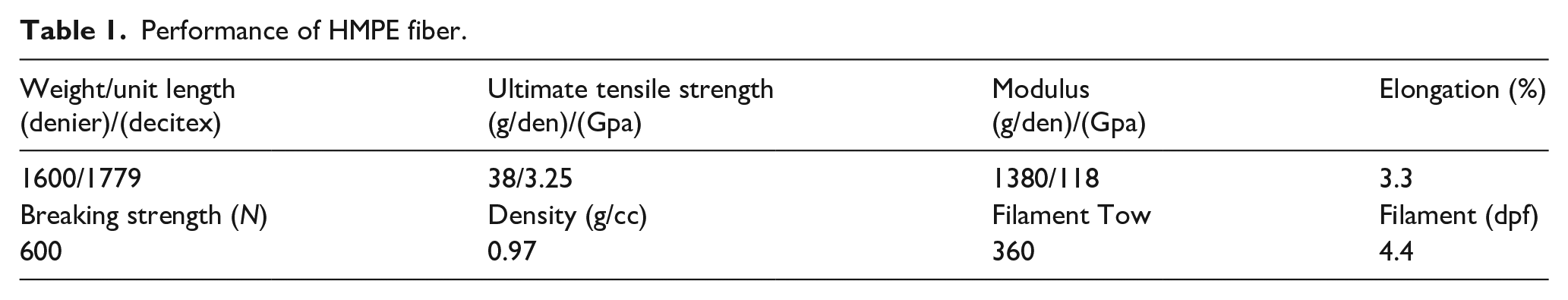
Graphene was bought from Ningbo Moxi Technology Co., Ltd., the average thickness of the graphene sheets is 2.4 nm and the size of the sheets is between 5 and 15 µm as given by the manufacture. Ethanol, Ecotone, and 3-aminopropyl triethoxysilane (APTES) are analytical pure and bought from Sinopharm Chemical Reagent Co., Ltd. Waterborne polyurethane is from Zhongfang chemical with the content of 35 ± 1% and the viscosity of 72.3 MPa.s and the PH = 7.
Yarn on yarn abrasion testing and infrared imager
The yarn on yarn abrasion equipment used in this study is designed according to ASTM D 6611-00: Standard Test Method for wet and dry yarn on yarn abrasion resistance, 30 as shown in Figure 1(a). A length of yarn is interwrapped in contact with itself between three pulleys that are positioned in a defined geometry to produce a specific intersection angle (34°). A weight is attached to one end of the yarn to apply a prescribed tension. The other end is drawn back and forth through a defined stroke at a defined speed until the yarn fails due to abrasion upon itself within the interwrapped region as shown in Figure 1(b). The device consists of four test ends and each test end can complete the independent yarn on yarn abrasion test. The device has the function of automatic stop when yarns break. The abrasion performance of yarns is characterized by abrasion cycles to break (CTB). According to the ASTM D6611, every sample repeated eight tests and the data validity would be checked according to the standard.

Yarn on yarn abrasion test equipment: (a) test deviceand (b) sketch map for testing.
The frequency of yarn abrasion can be changed by adjusting the rotation speed of the gear motor and the tension acting on the yarn could be changed by adjusting the tension weight.
To characterize the influence of the coating on temperature during the abrasion process, an infrared imager is arranged in front of the abrasion area to detect the temperature. The infrared imager used in this experiment is fluke TIS50 with a spatial resolution of 2.8 mRad, temperature measurement range of −20°C to 450°C, and an image resolution of 220 × 156 dpi.
During the experimental process, the abrasion area always swings, the infrared imager is employed to capture and track the maximum temperature within the abrasion area.
Thermal conductivity and coefficient of friction test
Therm TCi thermal conductivity analyzer® was used to measure the thermal properties like conductivity, resistance, and effusivity. This highly accurate technique is based on the transient plane source (TPS) method. The primary difference between the traditional and modified TPS (MTPS) techniques is that the modified method offers a single-side interface compared to the double-sided interface requirements of the traditional version. The MTPS technique has many advantages in comparison to other available testing methods, for example, guarded hot plate, hot wire, or hot probe. The noninvasive nature of the C-Therm TCi’s MTPS sensors allows the testing of materials of any size in situ or in laboratories without the destruction of the specimen. Moreover, testing can be done in seconds with consistent and accurate results. The C-Therm TCi consists of a sensor, a power control device, and computer software, as shown in Figure 2. A spiral-type heating source is located at the center of the sensor where heat is generated. The generated heat enters the material through the sensor during which a voltage drop occurs rapidly at the heating source. The thermal conductivity is calculated through the voltage drop data.

Therm TCi thermal conductivity analyzer system 31 : (a) yarn sample, (b) MTPS sensor, (c) load control, and (d) data analysis and display.
The coated samples are laid on the glass plate in parallel and evenly to ensure that there is no gap between the fiber bundles and the glass plate is not exposed. The layer thickness is 5 mm. Before the test, all the samples were conditioned in standard atmospheric with a temperature of 25°C and 65% relative humidity before testing for 24 h.
The coefficient of friction (COF) is an important parameter to characterize the surface properties. In this study, the COF was tested employing the ATTRIFIL III 233C which is a specialized COF testing device for synthetic yarns.
Coating preparation
Nano graphene is a two-dimensional layer structure. Due to nano-size effects and inorganic properties, it tends to agglomerate in an aqueous solution, which would lead to uneven coating. At the same time, due to the absence of active groups on the surface of graphene, the adhesion between graphene and fiber is not firm. To achieve uniform dispersion and firm bonding, graphene was grafted and then mixed with polyurethane to form composites coating. 28 So, the coating process includes two steps, the first step is to prepare the functional graphene, and the second is to obtain the functional graphene and polyethylene coating (FG/PU).
The preparation method of functional graphene is as follows: 2.0 g of 3-aminopropyltriethoxysilane is dissolved in 7.2 g deionized water and 0.8 g ethanol, 0.1 g graphene is added after mixing, and then reacted in an oil bath at 60°C for 6 h. After the reaction, it is washed three times with deionized water and ethanol, centrifuged, and freeze-dried to obtain functional graphene.
The preparation process of FG/PU is as follows: dissolving 0.0125 g functional graphene into a certain amount of ethanol, dispersing 1 h by ultrasonic, adding 5 g water-soluble polyurethane emulsion and mixing 5 min with magnetic stirrers to make it mix evenly, vacuuming 10 min to remove bubbles in the mixture, 0.25 wt% FG/PU could be obtained. Other coatings with different content could be obtained following the same steps.
To make the HMPE fiber manufacture process goes smoothly, it’s common to add some oil on the surface of fibers, which may affect the coating effects. To avoid this negative influence, it’s necessary to wash the oil away using alcohol, as shown in Figure 3. Then, HMPE yarns would be coated by kiss roll with FG/PU composites as a coating bath. After coating, the yarns are fully dried by a heating and drying device at 40°C–60°C, and finally, the yarns are wound on a spool. During the coating process. The coating fraction was controlled at 20%–25% by adjusting the tension of the kiss roller and pressure roller.

FG/PU preparation and coating process: (a) 0FG/PU, (b) FG/PU0, (c) FG/PU25, (d) FG/PU50, (e) FG/PU75, and (f) FG/PU100.
Five kinds of FG/PU coatings with different FG weight contents were prepared, that were 0 wt%, 0.25 wt%, 0.5 wt%, 0.75 wt%, 1 wt%, respectively, They were represented by FG/PU0, FG/PU25, FG/PU50, FG/PU75, FG/PU100, that is to say, FG/PU0 means that the yarns were coated by PU without FG, FG/PU25 means that the yarns were coated with FG (0.25 wt%) and PU composites coating, others are following the same method. 0FG/PU was used to denote the uncoated HMPE yarns.
Results and discussion
Effect of FG/PU coating on friction properties of HMPE yarn
Effect of graphene content abrasion life
Graphene is used as an additive in the coating, and the effect of its addition on the performance can help us to determine the optimal addition amount. The influence of graphene content on abrasion properties is discussed by adding 0 wt%, 0.25 wt%, 0.5 wt%, 0.75 wt%, and 1 wt%, respectively, uncoated HMPE was also discussed. Figure 4 shows the variation diagram of the yarn abrasion performance with different graphene contents at the abrasion frequency of 1 Hz and tension of 35 mN/tex.

Effect of graphene content on HMPE yarn on yarn abrasion and coefficient of friction.
It can be seen from Figure 4 that the CTB of FG/PU0 is about 18634 cycles. With the increase of graphene content, the CTB almost increases linearly. When the addition amount reaches 0.5 wt%, the CTB reaches uptown 26,149 cycles, with an increased rate of 76.2%. As the continuous increase of the functional graphene, the CTB of yarns is still increasing, while the growth rate slows down. Generally, the addition of graphene can improve the effect of polyurethane coating. With the increase of graphene content, it firstly showed rapid growth and then a gentle regional trend. From the economic point of view, it can achieve an ideal effect if the addition of graphene is controlled between 0.5 wt% and 0.75 wt%.
Different from the increasing trend of CTB, the coefficient of friction decrease with the addition of graphene. For uncoated HMPE, the COF is about 0.51. For HMPE only coated with PU, the COF is about 0.47, so the PU could lubricate the HMPE fiber in a certain. By adding the functional graphene, the COF decreases further.
Effect of coating on abrasion performance at different frequencies
Under different working conditions, the yarn on yarn abrasion frequency would be different. Frequencies have a great impact on the yarn on yarn abrasion performance. To explore the protective effect of coating, the yarn on yarn abrasion of coated HMPE with different frequency and different graphene content were carried out as shown in Figure 5.

Effects of coating on the abrasion properties of HMPE at different frequencies: (a) the influence of frequencies on the abrasion performance and (b) the comprehensive effect of different graphene contents and frequencies on the abrasion performance of HMPE.
It can be observed from Figure 5(a) that for the uncoated yarn sample 0FG/PU, the CTB increases gradually from 10,520 cycles to 14,834 cycles when the frequency increases from 0.25 Hz to 1 Hz. It increases. With the further increase of abrasion frequency, the CTB decreases rapidly. At 1.25 Hz, the CTB decreases to 10,326 cycles, which is lower than that at 0.25 Hz. At 2 Hz, the CTB decreased to about 6287, only 42% of that at 1 Hz. The main reason for this change is that at low frequency, due to the slow abrasion, the heat generated during the abrasion process can be exchanged with the external environment in time, to maintain a relatively low temperature. At this time, the damage of the HMPE is mainly due to mechanical wear. With the increase of frequency, the surface temperature of the HMPE increases gradually and softens the fiber surface. Under the combined action of temperature, pressure, and fiber reciprocating, a smooth membrane structure is formed on the fiber surface, 7 which reduces the friction coefficient and improves the yarn on yarn abrasion life. When the friction frequency is greater than 1 Hz, the thermal effect gradually plays the leading role and deteriorates the mechanical performance of HMPE fiber.
For FG/PU0 with only PU coating, the trend is relatively stable. The CTB decrease with the increase of abrasion frequency. When the friction frequency is less than 1 Hz, the decreased amplitude is relatively little. When the friction frequency is greater than 1 Hz, the decline speed is accelerated. With the increase of abrasion frequency, the heat gradually accumulates, and the temperature rises, the mechanical property damage of fiber is also gradually increased, which leads to the decline of HMPE abrasion performance. Therefore, the CTB is the highest at the lowest frequency of 0.25 Hz. When the frequency is higher than 1 Hz, the heat accumulation is faster, the temperature increases, and the CTB decreases rapidly. In general, the PU coating has a good effect on the fiber, especially in the low-frequency state. At all frequencies, the CTB of PU coated yarn is bigger than that of uncoated yarn.
For FG/PU25, FG/PU 50, FG/PU75, and FG/PU100, there are different trends compared with FG/PU0. For FG/PU25 with a small amount of graphene, the CTB with low frequency (0.25 Hz–1 Hz) has the same downward trend as that of FG/PU0 without graphene, but the overall life is improved. When the frequency is higher than 1 Hz, CTB does not decrease as much as FG/PU0. The reason is that at low frequency, the heat exchange is sufficient, and the increase of temperature leads to the formation of the lubricating film between fibers, and the friction coefficient between fibers decreases thus improves the CTB. When the frequency is higher than 1 Hz, more heat will be accumulated. At this time, graphene has a good heat conduction function, which can conduct the heat in time and keep the yarn at a relatively low temperature. As the friction coefficient of fiber surface film decreases further, the CTB reaches the highest. When the frequency increases further, the temperature also increases, which leads to a decrease of HMPE mechanical performance.
It can be seen from Figure 5(b) that the addition of graphene has a significant effect on high-frequency abrasion. With the increase of the amount of graphene, the heat conduction of graphene can play a role in the low-frequency state, which makes the CTB rise with the increase of frequency. The maximum value appears at the frequency of 1.25 Hz. When the abrasion frequency is higher than 1.25 Hz, the heat conduction of graphene can not counteract the heat generation rate, which makes the temperature rise further, thus reducing the CTB. Graphene, as an additive with good thermal conductivity and lubricity, plays a unique role in the coating. It can further enhance the lubricating ability of polyurethane coating at low frequency and play a better thermal conductivity at high temperatures.
Effect of coating on abrasion performance under different tension
In addition to frequency, another important factor affecting the abrasion performance of HMPE is the tension applied to the yarns. The tension on HMPE yarn plays two roles, one is the tension on the yarn axis direction, the other is the pressure between yarns in the vertical direction of the yarn. During the repeated abrasion process, the tension on the yarn axis accelerates the creep of the HMPE, and the positive pressure in the vertical direction of the HMPE yarn axis increases the friction between the yarns and the heat generation. Therefore, the tension has an important influence on the abrasion performance of the HMPE. According to ASTM D 6611-00, the abrasion performance of HMPE under three tension levels of 20 mN/tex, 40 mN/tex, and 60 mN/tex at 1 Hz abrasion frequency were studied as shown in Figure 6.

The effect of yarn tension on the abrasion life of coated yarns: (a) the change of abrasion life with tension and (b) the comprehensive effect of graphene content and tension on abrasion life.
It can be obtained from Figure 6(a), all curves show a downward trend with the increase of tension. For the uncoated sample 0FG/PU, the CTB is about 18,720 at low stress (20 mN/tex). When the stress increases to 40 mN/tex, CTB decreases to 14,834 with a decrease of 20.7%. When the tension increases to 60 mN/tex, the CTB reduces to 8456 with a decrease of 42.9%. It can be concluded that the higher the stress level, the greater the reduction. For the FG/PU25 sample with less graphene content, the decrease rate of the sample is relatively slow due to the lubricity and thermal conductivity of graphene under a high-tension state due to the addition of graphene. With the increase of graphene content, the lifetimes of FG/PU50, FG/PU 75, and FG/PU100 decrease slowly with the increase of tension, especially in a high tension state.
This is mainly because the FG/PU coating forms a protective film among yarns under the low tension state, which reduces the friction coefficient and prolongs the CTB. When the tension increases, the positive pressure among yarns increases, and the heat generated by each friction increases. The existence of graphene can accelerate the heat transfer and ensure that the temperature of the fiber is at a relatively low level. The more graphene content, the more significant the effect of heat transfer. Therefore, the CTB of FG/PU100 at 60 N/tex is bigger than that of 40 mN/tex, and 40 N/tex is longer than 20 N/tex. It can be concluded that from Figure 6(b) that the addition of graphene above 0.5% can significantly enhance the abrasion performance of the fiber under a high-tension state.
Mechanism of FG/PU coating to improve the yarn on yarn abrasion performance of HMPE
FG/PU coating can significantly improve the abrasion performance of HMPE yarn, especially under high frequency and high stress. This part will further elaborate on how FG/PU can improve the yarn on the yarn abrasion condition and prolong the CTB.
Effect of FG/PU coating on HMPE morphology
In the abrasion process of HMPE, the macroscopic abrasion phenomenon can be observed directly. Through these phenomena, we can analyze the failure mechanism and progress of HMPE fracture.
It can be seen from Figure 7(a) to (c) that the HMPE surface is smooth before abrasion. After 1000 cycles of abrasion, a small amount of hairiness appears on both ends of the abrasion area. With the abrasion going on, the amount of hairiness increases and accumulates at both ends. When the abrasion reached 6000 cycles, the yarn fineness decreased significantly, the number of broken yarns increased, and the abrasion area was covered with hairiness. It can be seen from Figure 7(d) that transverse cracks appear on the surface of the fiber after abrasion, and the local splitting phenomenon appears. In contrast, the number of hairiness and transverse cracks in FG/PU50 is relatively small, and the crack density is also little, and there is no longitudinal splitting. This shows that the FG/PU coating can effectively protect the HMPE from failure.

Abrasion damage evolution: (a) uncoated yarn, 0 time, (b) uncoated yarn, 1000 times, (c) uncoated yarn, 6000 times, (d) uncoated yarn SEM, 6000 times, (e) FG/PU50, 0 time, (f) FG/PU50, 1000 times, (g) FG/PU50, 6000 times, and (h) FG/PU50 SEM, 6000 times.
Effect of FG/PU coating on the thermal effect of HMPE
The thermal conductivities of HMPE were tested by the thermal TCi thermal conductivity analyzer, as shown in Table 2.
Comparison of thermal conductivity of different coated yarns.

The thermal conductivity of HMPE yarn without any coating is 0.125 W/(m·K), and the corresponding thermal emissivity is 59.12 W·m−2·S1/2·K−1. By coating PU on HMPE fiber, the thermal conductivity decreases to 0.101 W/(m·K), and the thermal emissivity also decreases. This is mainly due to the poor conductivity of the polyurethane coating itself. When the content of graphene is 0.5 wt%, the thermal conductivity of the coated HMPE increases to 0.253 W/(m·K), which is twice as much as that without coating. When the content of graphene increases to 1 wt%, the thermal conductivity increases to 1.593 W/(m·K), which is 12 times higher than that of HMPE fiber without coating. At the same time, the thermal emissivity of HMPE increases greatly. The improvement of thermal radiation capacity will delay the rise of HMPE fiber temperature and improve the abrasion life of HMPE fiber. This can also be obtained from the temperature curve of HMPE yarn during friction, as shown in Figure 8.

Temperature changes during the abrasion: (a) the abrasion frequency: 1 Hz, the pretension: 40 mN/tex, and (b) and (c) the infrared images of the HMPE during the abrasion.
In the process of yarn on yarn abrasion, the heat generated leads to the increase of temperature. With the help of fluke® TIS50 infrared imager, the yarn surface temperature and temperature changes during the abrasion process could be measured and recorded, as shown in Figure 8. Due to the continuous swing of the yarn during abrasion and the frequency of data acquisition, the temperature shown here is the highest temperature in a certain period. It can be seen that all six curves can be divided into two groups, one group is for 0FG/PU and FG/PU0. The yarn surface temperature of these two curves is relatively high, and the stable temperature is between 65°C and 68°C. The abrasion cycles to reach a stable temperature is about 2000 times. In the abrasion process, the friction coefficient of FG/PU0 is relatively less and the heat generated is also less due to the existence of PU coating on the surface. Therefore, the rate of temperature rise is relatively low. However, with the abrasion, the heat accumulated continuously. Due to the poor thermal conductivity of PU, the heat generated could not be diffused in time. Subsequently, the surface temperature of FG/PU0 was higher than that of 0FG/PU. For the coated HMPE containing graphene, the surface temperature of the yarn is relatively lower. The higher the content of graphene is, the lower the temperature is, and the bigger the cycles to reach a stable temperature. From the images of the infrared imager, as shown in Figure 8(b) and (c), the more graphene content, the greater the heat dissipation length on the yarn. In other words, the heat generated in the abrasion area can be transferred along the length direction of the yarn, thus increasing the effective area of heat dissipation and keeping the overall temperature at a low level. This further shows that the addition of graphene has a positive effect on heat transfer and heat dissipation.
Conclusion
Aiming at the shortcomings of HMPE fiber with a low melting point and poor thermal conductivity, the yarn on yarn abrasion performance of HMPE was improved by adding functional graphene and polyurethane composites coating. With the help of infrared imaging technology and thermal Tic equipment, the effect of the amount of graphene added on the friction performance, the effect of friction frequency, and yarn tension on different coatings was discussed. Based on the monitoring of the HMPE abrasion process, the mechanism of yarn on yarn abrasion failure was investigated. The conclusions are as follows:
(1) The addition of graphene has an important influence on the HMPE yarn on yarn abrasion performance. The abrasion performance of HMPE increases with the increase of graphene content. When the content of graphene is more than 0.75 wt%, the increase of CTB tends to be gentle. Therefore, to ensure the coating effect, the addition of graphene should be more than 0.75 wt%.
(2) FG/PU coating has a different reaction to abrasion frequency and yarn tension. For the abrasion frequencies, the addition of FG/PU coating improves the high-frequency abrasion performance of HMPE yarn, especially with the increase of graphene content. This is mainly due to the good thermal conductivity of graphene. For different yarn tension, the abrasion performance of all samples decreases with the increase of pretension. The application of the FG/PU coating reduces the coefficient of friction, thus reduces the heat generation, and makes the coated yarn more suitable for high tension conditions.
(3) FG/PU coating can form a protective film on the surface of the yarn, which plays the role of lubrication and heat conduction, effectively reduces the mechanical wear in the process of yarn on yarn abrasion, and diffuses the heat generated in the process of friction, and maintains a lower temperature on the fiber surface, thus improve the yarn on yarn abrasion performance.
Footnotes
Declaration of conflicting interests
The author(s) declared no potential conflicts of interest with respect to the research, authorship, and/or publication of this article.
Funding
The author(s) received no financial support for the research, authorship, and/or publication of this article.