
Abstract
The good formability of textile composite materials over complex mold geometries is one of the reasons to make their use expanding in various modern industries. However, different defects in these reinforcements could have occurred during the forming step in the manufacturing process. The defects are arising for many reasons; some are related to the fabric itself and others related to the draping parameters. Understanding the textile structure mechanics and draping behavior is essential to choose the proper reinforcement as well as to attain better simulation. Fabric wrinkles and local out-of-plane bucking of yarns were the fundamental defects in focus. The main objective of this part of the project was to experimentally investigate and compare the draping behavior of six commercially available glass fabrics from the same category of warp-knitted non-crimp fabrics (WKNCFs). The tested fabrics included two stitching patterns: tricot and chain. Also, they were relatively heavy with approximate mass per square meter. A double-dome punching test was performed to implement draping for each fabric; then, the defects were detected and characterized. Punching load-displacement curves were also recorded. In addition, a defect code was designated for the main defects to characterize forming defects at the meso-macroscopic scale. The structure and the number of fabric axes, stacking sequence, and stitching pattern all contribute to defect formation during draping. The studied configurations in this paper can help in studying the simulation of deformed technical fabric and provide a method to minimize and even eliminate the draping defects.
Keywords
Introduction
Textile composite materials are a steady rising direction, continuously improving both in industry and in research, due to the massive options for reinforcement materials, structures, and arrangements as well as every new-coming matrix materials. 1 As low-cost and high-production rate manufacturing processes are in high demand to be utilized in many applications, liquid composite molding (LCM) is extensively used in aerospace, automotive, and construction.2,3 Draping the fabric over the mold before resin injection is a crucial procedure in manufacturing success. 4 Based on the high potential for automation of this process (which is also called automated preforming), 2 the costs could be further reduced, and the quality could be increased.5,6 Numerical modeling can also help much to understand the draping process deeply and define its parameters. 7 Understanding the fabric behavior is especially important for the relatively new and promising structures such as warp knitted non-crimp fabrics (WKNCFs), 8 to discover their potential and drawbacks through manufacturing processes, particularly during the forming of complex-shaped parts.2,9 It is a pressing need to accurately characterize and predict these reinforcements behavior in the draping procedure. 10
The focus is on the fabric behavior and the local deformation after draping, which still a challenging problem for composite designers. 2 The experimental characterization of defects for different fabrics can help in numerical simulations, which become increasingly important.5,11 Textile structures generally have anisotropic nature, which makes the simulation of drape more sophisticated.5,12 Furthermore, fabric draping behavior can be determined according to different scales. On the macroscale, the fabric is supposed to be a macro-scopic continuum having homogenized anisotropic material properties. While on the mesoscale, single rovings and stitching yarns, which constitute the textile structure, are modeled. At this scale, the roving and stitching interaction plays a significant role in model accuracy. 13 However, on the microscale, the single filaments composing the yarn itself in the textile structure are modeled. The higher the level of detail, the higher is the necessary computing power.5,14 Therefore, macroscale is mostly used in industrial processes.5,15
Warp knitted non-crimp fabrics
Knitted fabrics have some critical advantages for composite reinforcement over woven fabrics. Warp knitted non-crimp fabrics (WKNCFs) are advanced types of textile fabrics that can consist of multiple plies of uni-directional fibers stacked with varied orientations and grouped altogether by warp knitting stitching, which mainly increase the structural stability during handling. 16 The in-laid knitted constructions combine excellent processability due to the ability to use dry fibers, with exceptional mechanical properties due to there is “no crimp” in the currying-load yarns.17,18 Since the warp-knitting technique is the most flexible and versatile method to produce NCFs, 8 WKNCFs can be produced with a wide range of areal densities from light to quite heavy fabrics with any staking sequence desired for the application.8,19
The fabric structure difference between WKNCFs and other fabric architectures makes defect formation mechanisms relatively different due to the presence of stitching yarn. 20 Thus, their behavior as multi-axial multi-layer fabrics should be deeply investigated.
Drapeability and double-dome drapeability test
Drapeability meaning is defined quite differently depending on the application. In garments and curtains, drapeability is the way of folding when fabric cover something or freely hang. 21 However, the definition for textile-reinforced composites is very different: where two-dimensional textiles are forcibly shaped into three-dimensional geometry, but folds are considered as defects, and they are not accepted. 22 Drapeability tests for the forming stage from composite manufacturing cycle have been largely developed to investigate and validate the material models such as woven and knitted structures (including multi-axial NCFs).5,6 Several geometries have been used to test the fabric drapeability in a similar manner to the industrial draping process in a mold. 5
The double-dome apparatus is one of the experimental devices repeatedly used for textiles forming tests (for mono- or multi-sheet forming). 23 It has a reasonably complex shape, from the industrial origin, 24 and it is useful to calibrate the material models in the finite element package. 25 It was benchmarked by several research groups,23,25 and can be used to evaluate the utility of current simulation techniques. 24
The experimental results of the drapeability test are the force-displacement data as well as the local deformations and may be defects in some textile sheets after draping. During the forming process, especially over complex geometries, local and global deformations occurred which are related to various parameters. 5 Different undesirable defects could appear locally and/or globally, and some of these defects are unique and not similar when draping any other fabric on the same geometry. 26 Wrinkling is one of the leading and most typical issues for sheet forming regardless of material nature. 27 It is also the most common and main defect that appeared at the end of the forming process of textile composites (in dry or even prepreg form); increasingly develops in multi-layers fabric. 27 Besides, there are yarn local buckling defect, 28 yarn bunching in woven fabric, 13 tow/roving bunching in NCF, 29 and nesting/branching. 2
Many studies in fabric composite literature have been devoted to experimentally investigate draping behavior for dry fabrics of carbon woven fabrics,30 –32, carbon 3D woven fabrics, 33 glass non-crimp 3D woven,34,35 and for glass woven fabrics.2,36 Also, warp-knitted non-crimp fabrics; like uni-directional 37 and biaxial. 11 Various punching geometries have been used for draping to investigate fabric behavior on more realistic forming conditions under combined loads; as, hemisphere,2,11,16,20,31 double-dome punch used in many studies,24,25,38,39 tetrahedron34,40 –42 along with less familiar draping geometries like prism punch41,43,44 and square box punch.41,44 Other textile structures such as multi-axial fabrics, especially with relatively heavy areal densities, need much more attention for a deeper understanding of their draping behavior over three-dimensional shapes. Thus, glass WKNCFs were chosen due to study their draping behavior; as no work has been done to investigate relatively heavy glass fabrics at about 1200 g/m2. Comparisons of their draping behavior were carried out using the double-dome punching test.
The objective of this paper was to characterize and analyze the out-of-plane draping defects of relatively heavy areal density glass WKNCF fabrics based on a double-dome shape forming. The draping defects were visually assessed, and the punching load was recorded for draping each fabric on the technical back and the technical face in three directions. For this purpose, the double-dome apparatus was set up, and six types of different glass WKNCFs were tested. The defects after draping were observed and the punching load was analyzed.
Materials
The materials for the experiment in this study were glass warp knitted non-crimp fabrics (glass-WKNCFs) from PGTEX® Company (Changzhou, China; product codes TM-L1250-7, E-LT1100-7, E-DB1200-6, TM-DBL-1200-6, E-DBT-1200-6, and E-DBLT-1200-6), the details in Table 1.
Summary of PGTEX® glass WKNCFs specifications.

UD: uni-directional; L: longitudinal; T: transverse; DB: double-bias; QX: quadri-axial; t: tricot; c: chain.
Measured areal density.
According to ASTM D1777 test standard. 45
Roving Tensile strength = 0.46 [N/tex] according to GB/T 7690.3 (ISO 3341) testing standard, 46 and Filament diameter = 17 [μm] according to GB/T 7690.5 (ISO 1888). 47
The fabrics had heavy areal densities and typical stitching patterns (tricot for UD, LT, DBL, and DBLT (QX); and chain stitching for DB and DBT) were investigated here. The photographs of these NCF fabrics of both faces are presented in Figure 1.

PGTEX® glass WKNCFs architecture. (a) Technical face. (b) Technical back (colored figure in the web version of this article.)
Each fabric was manufactured from more than one set of yarns. Each set of glass rovings was straight in its layer in the fabric sheet (in longitudinal, transverse, and bias directions). While the polyester stitching yarn by its smaller linear density, attach all the layers together throughout the fabric thickness. All fabric specifications and details are listed in Table 1. Each of the six fabrics had two, three, or four layers with different parameters with a relatively heavy areal density of about 1200 g/m2. However, for the UD fabric, the function of the layer on its technical back is just to support the fabric structural integrity and facilitate its manufacturing process 37 and it is only about 6% of the fabric areal density.
The 3D geometrical models of the fabrics were done using TexGen software (textile geometric modeller), 48 and both technical face and back with the notation of stitching patterns are shown in Figure 2. A small letter was added to the designated name of the fabric to easily distinguish the stitching type associated with each fabric: “t” for fabric with tricot stitching and “c” for those with chain stitching, appear in Figures 1 and 2.

3D geometrical model of fabric structures by TexGen softwae. (a) Technical face. (b) Technical back. (c) The stitching pattern without rovings and the notation.
Methods and experimental setups
A universal testing machine Instron 5967 with 30 KN load cell was employed as a forming machine; equipped with a double-dome punch arrangement that was manufactured to be connected to it, Figure 4. The total experimental setup employed to test the drapeability of textile reinforcements were shown in Figure 4. Sampling and cutting specimens for testing needs to ensure excluding the defects of NCF that may occur during production or handling, some of these defects are shown in Figure 3

Examples of possible defects in NCF. 49
The flat 2D WKNCF samples subjected to the double-dome punch in the vertical movement at a constant draping rate of 100 mm/min, with a maximum displacement of 60 mm. 49 This speed recommended for double-dome punching which corresponds to a cycle time approximately used in an industrial automated process 5 and also used by Rashidi and Milani 2 for hemisphere stamping.
The blank holding system restraints the fabric to the draw-in area in the die, where the local pressure can be simply controlled by adjusting the C-clamps or any other clamping device or springs (C-clamps were used in this study). The objective of using a blank holder was to create tension on the yarns and to prevent the extensive wrinkling, where the tension was inducing fabric tensile membrane strain by blank holder weight and the clamps.37,40 The magnitude of the pre-tension is dependent on the amount of pressure as well as the fabric-tools friction. Four C-clamps were set at 3.5 kg·cm to apply the same tightness on the blank holder at each holding point (this amount of pressure was also used by Rashidi and Milani 2 ). Similar to the actual forming situation, this boundary condition did not fully prevent the fabric from sliding to allow it to be drawn gradually. The weight of the blank holder imposes a uniform pressure, nonetheless, the further pressure can cause loss of cohesion.11,39
For the test, there are two components; the movable double-dome punch and the lower fixed assembly. The double dome punch can be moved with a defined velocity in relation to the lower assembly by adjusting the universal testing machine. The textile is draped when the punch is moved downwards, and the draping force is measured by the detection of the increasing load. The design and dimensions of double-dome punch introduced in the benchmark study, 25 and used by many researchers to investigate the forming behavior (also called experimental drapeability test). 5 The punch, the open-die, and the blank holder are shown in Figure 4(b).

The double-dome punch geometry. (a) Open die, and blank holder. (b) By SOLIDWORKS 3D design software.
After the forming and punch withdrawal, the deformations of the reinforcement were observed by a visual analysis (check) for the punched sample was implemented and local defects in the draped fabric were detected and analyzed. The results are categorized and then comparisons between fabrics and each test situation were done. The force-displacement curve was recorded during the test. For a clear view, extra lighting arrangement (also called backlit patterning technique) 2 was installed as shown in Figure 5. The lights are located above the fabric sample to clearly identify the draping defects across the deformed sample on the bottom view.

Photo of the experimental setup for the stamping operation. Instron machine, punch arrangement, and lighting.
Two series of experiments were implemented; punching the fabric face and punching the back. For each case, three configurations of punching orientation were carried out: at machine direction (longitudinal or production direction; 0°), at the cross-machine direction (transverse direction; 90°), and at bias direction (diagonal; 45°), as shown in Figures 6 and 7. In all tests of this study, one sheet of fabric in each configuration was punched (single fabric forming).

Double-dome punching configuration.

A sample of DB-c after marking prepared for cutting by “e-scissor.”
At the beginning of the test, the fabric sample was positioned accurately on the die plate matching the marking lines which help to ensure the precise positioning of the sample, then the blank holder put above then fixed by C-clamps.
Results and discussion
To facilitate forming defects characterization, a defect code was designated for the main defects in this study. The drapeability test results were the fabric formation by the double-dome punch, meanwhile the force-displacement data were recorded. The draping test results over the double-dome device were reproducible for the studied non-crimp fabrics which was also similar to the findings of Krieger et al. 5
Defect formation mechanics
During the punching process, the yarns (rovings) move rather freely with the punch at the bottom apart from the punch surface and are deformed adjacently in touch to the blank holder at the top, where the yarn is partly constrained by high friction forces in the punch-touched area and both ends of rovings can move trying to adapt the punch shape. In general, draping processes are conducted under low forces. These forces are needed just to permit force redistribution between adjacent stitch elements and/or to permit slippage of the stitches around the rovings. 30 Only frictional sliding between the stitches and rovings is possible, as the stitches originally wrap around rovings to hold them in place.30,50
Tensile stitch forces are generated during manufacture and also during certain fabric deformations (assuming that glass rovings are non-extensible). These forces lead to friction interaction forces between the rovings and stitches as these components undergo relative sliding (inter-ply sliding is specific to NCF forming and the stitching pattern ensure weak bonds between the glass fibers). 16 Moreover, fabric forming is a contact dominated problem, where friction between the components of the NCF certainly contributes to the resistance of the shear and cross-over sliding. 30 The tension of the stitching thread (in some cases) induced severe and irreversible defects to the WKNCFs. Additionally, the stitching pattern leads to different shear properties in different test directions, which result in an anisotropic performance for the fabric. 51 Consequently, the in-plane shear is highly related to wrinkling defects, whereas the stitching geometry influence the asymmetrical shear behavior of the fabric. 3
Essentially, wrinkle is a general defect in the preforming of fabrics (woven as well as other fabric structures), and it occurs when the energy needed for out-of-plane deformation is lower than that needed for in-plane shear deformation. Thus, the energy needed for in-plane shear deformation is higher. Then, the wrinkle defect is generated once the energy needed for out-of-plane deformation is lower than that needed for in-plane shear deformation. 3 Wrinkles are anticipated to grow along the same downward direction of forces induced by the punch. 2 However, each fabric structure at each punching configuration had its own specialty in relation to deformation characteristic and fabric architectural symmetry.
Observably the local buckling happens in the low-shear regions of the fabric, where the major deformation mechanism is the yarn bending rather than shear and lateral compaction. As the out-of-plane movement during the fabric punching cannot be freely compensated by shear, yarns are forcibly deviated from its fabric surface creating a buckle. 52 For easy representing the draping defects in this work, the next schematics – as defined and illustrated in Table 2 – was used.
Schematic coding of main draping defects (colored figure in the web version of this article).

Buckling is different from wrinkling; buckling happens in yarns (beam), whereas wrinkling occurs in the membrane (layer). 43 Many adjacent buckles could be considered as a wrinkle according to the definitive criterion. 55 Also, another defect can be added, which could irregularly appear in some cases; stitches dislocation: where it is a disturbance in stitches’ location from their proper place. 29 This defect was accompanying some severe buckles in the deformed fabric, especially when there was a set of roving bigger in size than other sets, an example shown in Figure 8, and it happened irregularly.

Stitch dislocation after draping.
The fabric needs to accommodate the increased width of occupied by a given number of yarns over the 3D part geometry in comparison with the corresponding width in the 2D flat fabric. As the same number of yarns will be distributed over the new width; therefore, yarn slippage and gapping will occur. 52 The slippage will be resisted by the stitches, which try to fix the rovings in their place, while the rovings themselves will accommodate the geometry by increasing the space. When the number of yarns is high enough, the gaps (the increase in spacing between rovings) will not be noticeable after draping the fabric.
The contribution of the stacking sequence in triggering defects during double-dome punching for the multi-layered NCF fabrics has been discussed in the following paragraphs for each fabric.
Quadriaxial WKNCF (QX-t)
Figure 9 showed a bottom view of the double-dome forming results of a set from quadri-axial WKNCF fabric samples (i.e. four layers) in three configurations for both sides, and Figure 11 illustrated a schematic drawing representing periphery of the die and dashed line for test direction in relation to the fabric. The characteristic areas in the punch are shown in Figure 10.
The punching result of single-layer double-dome forming test result of quadri-axial fabric (QX-t).
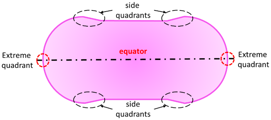
Naming guide for different areas in the punch.

Schematic representation of detected draping defects of quadri-axial fabric (QX-t), in three configurations on both fabric sides (colored figure in the web version).
The local buckles were observed near the quadrants of the two domes, and all the buckles were parallel to the flow of the glass rovings in the first outside layer. For punching the back: defects are apparent in all cases; in machine production direction, it induced buckles in four locations in a symmetrical manner to the punching axis (Figure 11: upper row left) while for cross-machine direction, the severe buckles appeared obviously on both dome sides of the punch, they were also symmetrical to the chain axis (Figure 11: upper row middle). However, for punching the bias direction (45°), both buckles and wrinkles appeared; they appeared on many locations near to the periphery of the die, also in a symmetrical manner to the chain axis as illustrated in (Figure 11: upper row right).
On the other hand, punching the face produced different patterns of draping defects for this fabric type where both buckles and wrinkles appeared together in each configuration in a symmetrical manner to the center point of the die circumference. For machine and cross-machine punching direction, the buckles and wrinkles were near the side quadrant points, but they were apart from each other (Figure 11: bottom row). However, for the bias direction, both buckles and wrinkles together were adjacent to each other appeared in both dome sides of the die near to the two extreme quadrant points (Figure 11: bottom row right).
Apparently, the results of punching the face were different from that of punching the back, and each direction had its own pattern of defects. Since this fabric had four layers, the defects appeared on the outer one where the movement of roving was restricted and the extra length buckled between the two stitches out of the fabric plane. Fabric wrinkle is waviness in all fabric layers altogether at certain locations, which it seemed like there was an excessive amount of fabric at that location. This fabric needs more investigation to find shapes that can be draped without defects or finding suitable methods to minimize them. As it has four axes, it is promising to manufacture durable parts in all directions.
Tri-axial WKNCF (DBL-t and DBT-c)
For one of the tri-axial fabrics in this research; DBL-t, punching results were shown in Figure 12. Defects were apparent in all cases of punching in a symmetrical manner to the chain axis as illustrated in the schematic drawing (Figure 13). Punching the back just produced one type of defects in each configuration; buckles, which they were formed from the longitudinal rovings near the side quadrants in both dome sides, but for cross-machine back punching, they appeared at the Equator of the punch; where there are high curvature zones (Figure 13: upper row middle).
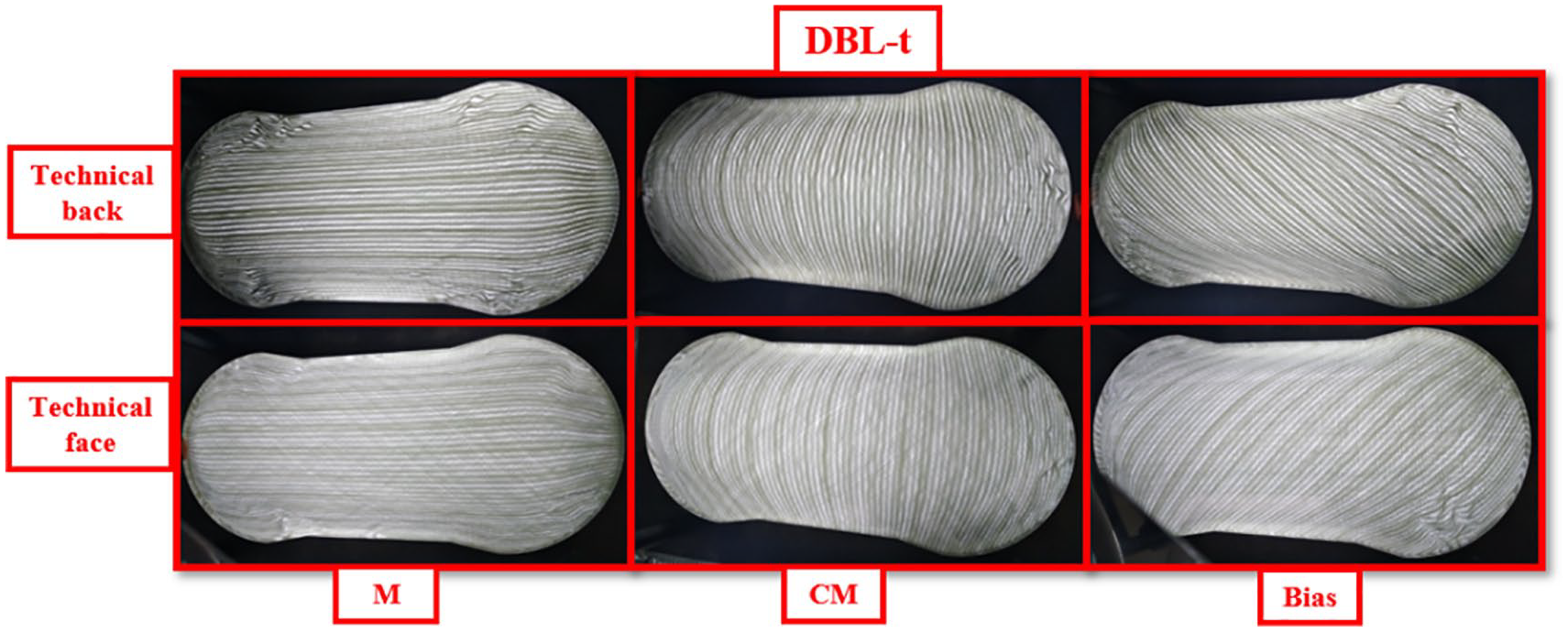
The punching result of single-layer double-dome forming test result of Tri-axial fabric (DBL-t).

Schematic representation of detected draping defects of Tri-axial fabric (DBL-t), in three configurations on both fabric sides (colored figure in the web version).
On the other hand, punching the fabric technical face produced wrinkles in all configurations near the side quadrants of die boundary, as illustrated in (Figure 13: bottom row).
For the other tri-axial fabric; DBT-c, defects were apparent in all cases on punching both back and face as shown in Figures 13 and 14. Nonetheless, they appeared in a different manner in comparison to DBL-t punching defects. They were more in quantity and mixed where buckles and wrinkles appeared together in each punching configuration. Whereas they were less and from one type for each configuration in DBL-t (Figure 13). In addition, there was a symmetry of defects’ locations to the center point in DBT-c (Figure 15) while the symmetry was to the chain axis in DBL-t fabric punching (Figure 13).

The punching result of single-layer double-dome forming test result of Tri-axial fabric (DBT-c).

Schematic representation of detected draping defects of Tri-axial fabric (DBT-c), in three configurations on both fabric sides (colored figure in the web version).
Both DBL-t and DBT-c had two 45° layers and the difference was in the third layer. In DBL-t, there was a longitudinal layer stacked outside in the technical face grouped with the other layers by tricot-chain stitching pattern. Being the outer layer gave it some freedom to manipulate through the tricot stitches in the fabric 3D form producing out-of-plane buckles in some longitudinal rovings and certain locations as aforementioned. Differently, DBT-c had a third layer stacked transversely in between the two ±45° and the three layers were grouped together by chain-chain stitching. The latter arrangement contributed in inducing wrinkles during draping. The middle layer buckled inside at certain locations which pushed the outer layer outside forming those wrinkles in all punching configurations (Figure 15). The same deformation mechanism could lead to understand the reason of wrinkles after punching the face of DBL-t samples where the longitudinal layer was inside in direct contact with double-dome punch surface (Figure 13: bottom row).
Bi-axial WKNCF (LT-t and DB-c)
For bi-axial LT-t fabric tests, defects were small in quantity and magnitude in comparison to tri-axial and quadri-axial fabric samples. They just appeared in some cases on punching the back or on punching the face (Figure 16). However, in the bias direction, there was a good draping appearance for punching both fabric sides (Figure 17: right column). Since imposing membrane tensile force along with the rovings in the bias direction would reduce the likelihood of local compressive forces generation, working as a driving force for de-wrinkling during forming. 2 Punching the back just produced one type of defects; small buckles in the machine and cross-machine directions. They were in the longitudinal rovings but appeared in a symmetrical manner to the chain axis as illustrated in the schematic diagram in (Figure 17: upper row left and middle). On the other hand, punching the face produced small wrinkles in the machine and cross-machine configurations, which were also symmetrical to the chain axis as illustrated in (Figure 17: bottom row left and middle).
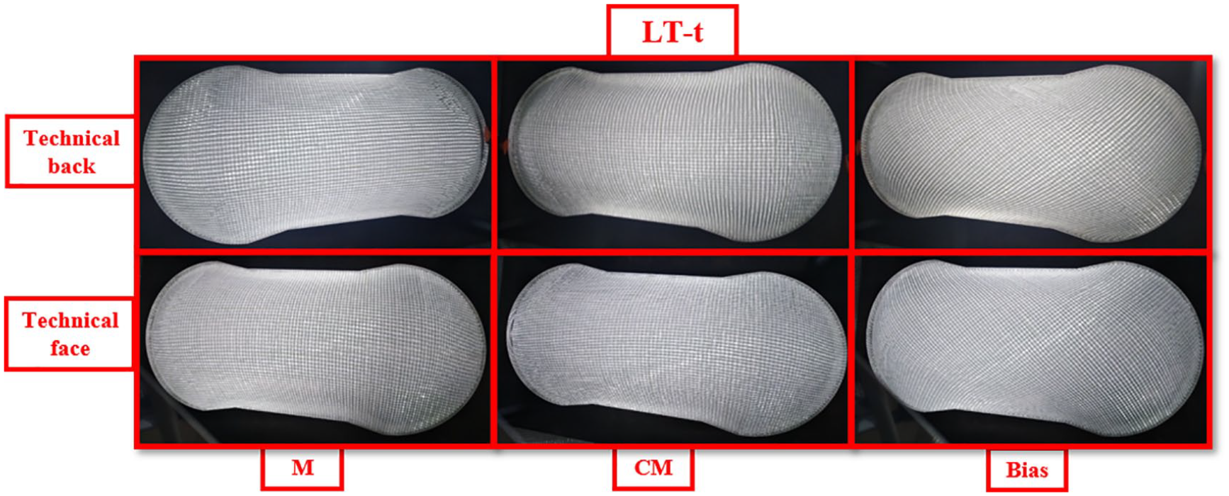
The punching result of single-layer double-dome forming test result of Bi-axial fabric (LT-t).

Schematic representation of detected draping defects of Bi-axial fabric (LT-t), in three configurations on both fabric sides (colored figure in the web version).
The defects formation trend for this fabric was similar to some extent to tri-axial DBL-t fabric but the defects were much smaller so that the fabric drapeability appearance was much better than it was in DBL-t fabric. The defects were formed according to the same mechanism of tri-axial samples. However, the stitching pattern was similar in both LT-t and DBL-t so that fewer layers grouped by the same stitching pattern (tricot-chain) offered fewer restrictions on rovings movement, which provided the structure more freedom to adapt the punch shape better; as stitches ensures weak bonds between the layers. 16
For bi-axial DB-c fabric, there was no visible out-of-plane wrinkling observed on the fabric over the double dome, also, there is no local buckling in the rovings and no stitch dislocations in all cases at the end of the draping test as seen in Figure 18. This means that this fabric had good drapeability over the double dome geometry as illustrated in Figure 17. The chain-chain stitching pattern gave the structure more freedom to adapt the punch shape in comparison to the tricot-chain pattern due to the independence of each chain in the first pattern. Experimentally fiber buckling represented as compressive fiber stress in simulation which appeared in draping carbon (±45) chain knitted NCF.31,56 As the tension of the stitches at the initial orientation of the primary roving may vary due to shearing, the level (magnitude) and the position of the local wrinkles were affected. 20 Similarly, DB-c and DBT-c could be compared. where there were no defects in the draping of DB-c. Subsequently it had good drapeability over a complex shape like double-dome punch as could be seen in Figure 19.

The punching result of single-layer double-dome forming test result of Bi-axial fabric (DB-c).

DB-c fabric draping result in the bias direction.
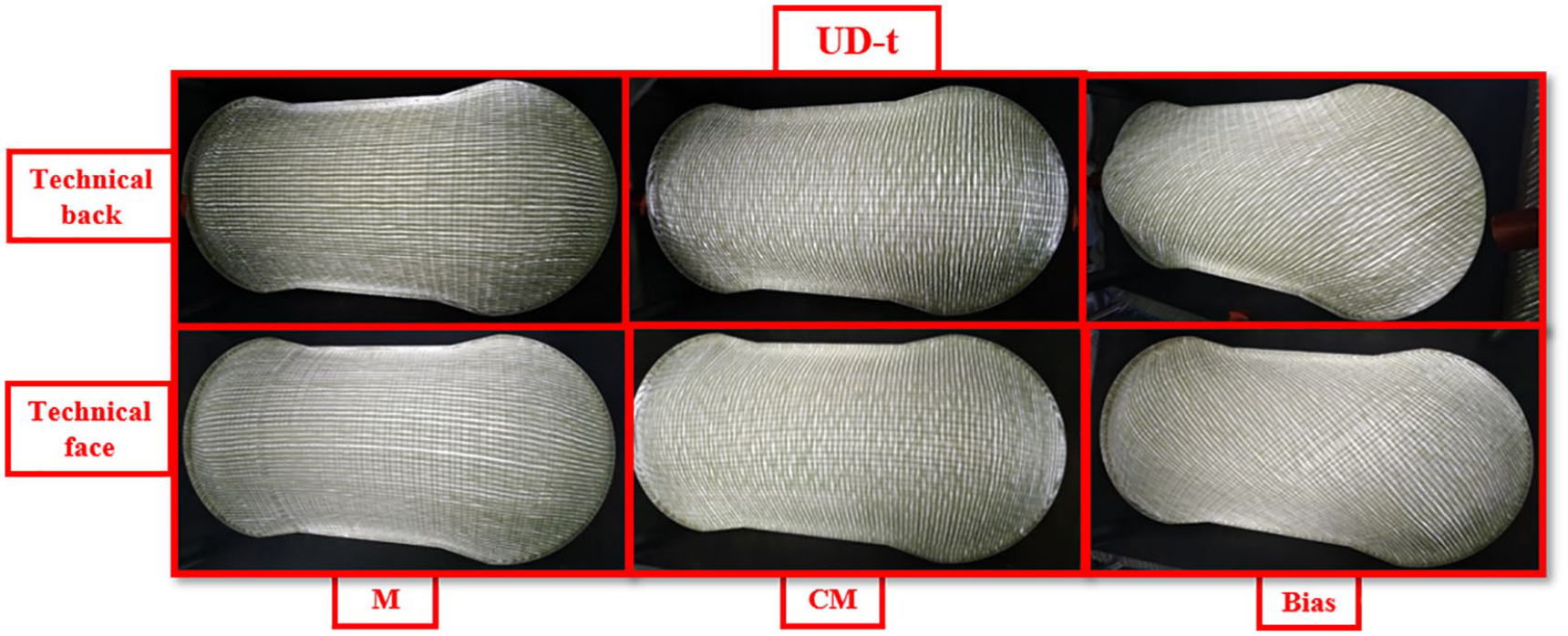
Mono-axial WKNCF (UD-t)
Figure 20 presented the double-dome forming results of three configurations for both sides of UD-NCF fabric (bottom view). There is no visible out-of-plane wrinkling observed on the fabric over the double-dome. Besides, there is no local buckling in the rovings and no stitch dislocations in all test cases. Moreover, there was no gapping between glass roving bundles; which was observed by Schirmaier et al., 37 in hemisphere draping of carbon UD-NCF. Since the stiffness of fabric with tricot pattern is lower than that with chain pattern, it is easier to conform the punch shape. 51

Single layer double-dome forming test result of UD-NCF (bottom view).
No draping defects means that this fabric structure has a good drapeability over a complex geometry like the double-dome shape. Preforming quality is important for the properties of the final composite part, therefore, this structure of WKNCF is widely used for automotive applications. 57 Also, in industrial scale and according to Seartex Company the UD-NCF give an extra advantage of 15% faster processing in wind turbine manufacturing. 58
Unlike woven structures, there is no shear locking for NCFs which may provide excellent drapeability over complex geometries, 51 if the fabric stiffness due to stitching restrictions allow these fabrics to drape with good quality without defects. 3 However, more stacked layers (three or four as in this study) induce extra restrictions to the WKNCF structure and consequently produce poor drape quality.
Finally, the force-displacement curves during punching for all fabrics in three configurations were presented in Figure 21 to provide an overall idea about the studied force in all configurations. There was an increase in the punching load by increasing the number of layers in the fabric. However, the loading was in the same range in all punching directions for both face and back. Comparatively, the measured force progressions are very similar (the same die is used for all fabric samples) like to the trend found by the researchers Rashidi and Milani, and Krieger et al.2,5 Then it increased rapidly at the end of the draping process. From a primary comparison, the required forming force for UD and LT were the lowest in all configurations, whereas for QX and tri-axial, DBT and DBL, were higher than other fabric samples in all configurations. As more layers with different orientations are stitched together in one structure, the reason will make the fabric stiffer and consequently, the required punching force will be higher. Many factors (tool-fabric friction, fabric-fabric friction, layers stacking sequence, and orientation . . .) affect the resultant punching force which could be further investigated in future studies.
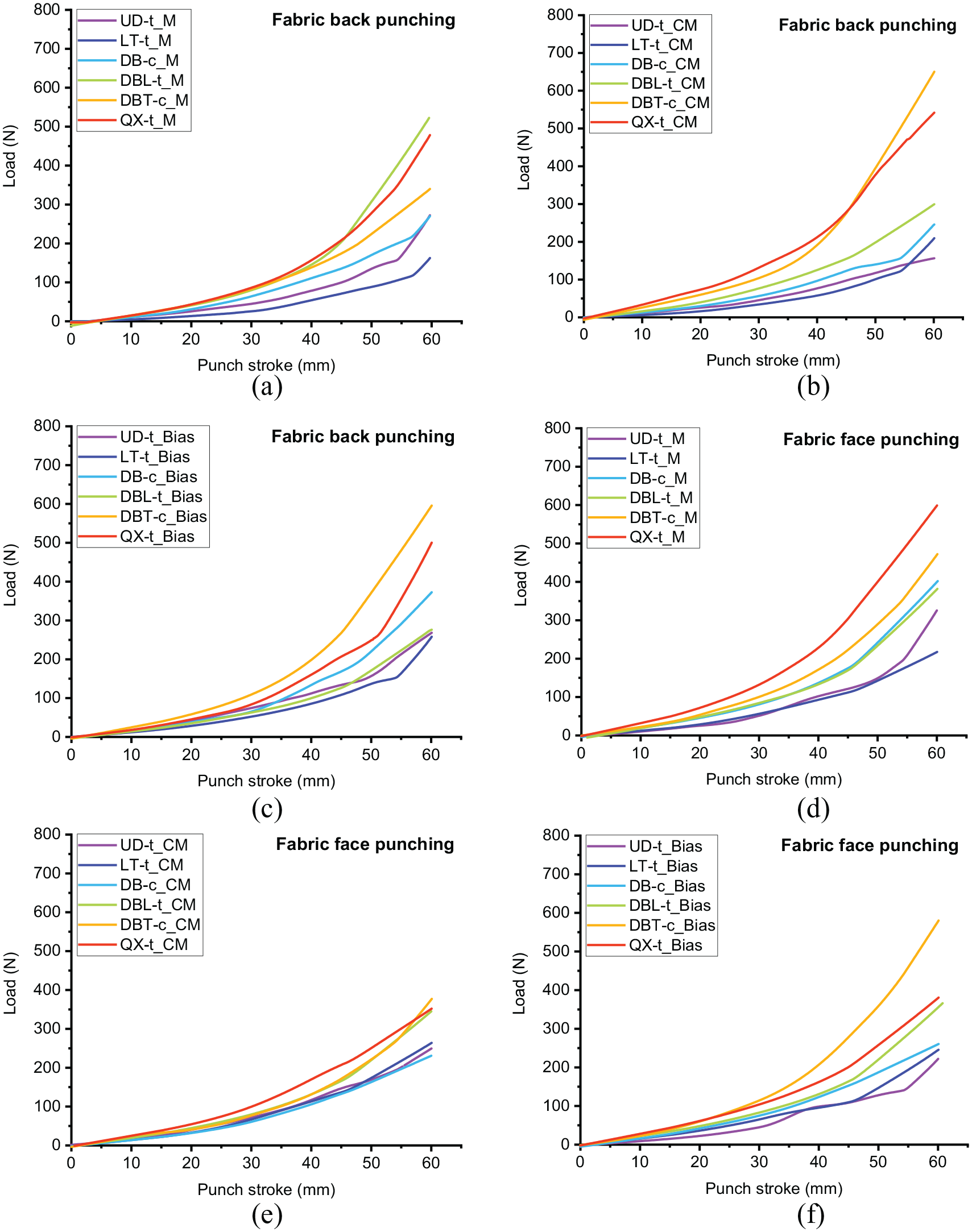
Force-displacement curves of punching all fabrics in three configurations. (a) Back machine direction. (b) Back cross-machine direction. (c) Back bias direction. (d) Face machine direction. (e) Face cross-machine direction. (f) Face bias direction (colored figure in the web version).
Conclusion (summary and outlook)
In the present paper, a draping test for formability by the double-dome geometry for six different types of glass-WKNCFs was investigated. The main forming defects, wrinkles, and buckles were detected. In addition to a comparison among the fabrics in the studied cases and the required punching force were considered.
The structure and the number of fabric axes, stacking sequence, and stitching pattern all contribute to defect formation during draping. However, some fabrics (UD and DB) have well drapeability in all tested configurations. Whereas, some other fabrics (QX and DBL) have bad drapeability with severe defects. Nevertheless, some fabrics like (LT) has good drape behavior (no defects) in one direction and bad drape behavior (with small or large defects) in other directions. The studied configurations in this paper can help in studying the simulation of each fabric and open the doors to a method by which draping defects can be minimized and even eliminated.
This study can show the effect of different fabric structures having an approximate mass per square meter on draping behavior over the same shape (double-dome), further modeling on different scales and implementing the drapeability test for other reinforcements including the hybrid ones are also recommended. More extensive research is also required to automate the forming step in the manufacturing process of fabric-based composites.
Footnotes
Declaration of conflicting interests
The author(s) declared no potential conflicts of interest with respect to the research, authorship, and/or publication of this article.
Funding
The author(s) disclosed receipt of the following financial support for the research, authorship, and/or publication of this article: This work was financially supported by the National Key Research and Development Program of China (2016YFB0303300), the National Natural Science Foundation of China (11472077), and the Fundamental Research Funds for the Central Universities (2232020A-05, 2232020G-06).