
Abstract
In addition to carding and airlaid processes, nonwovens are produced from staple fibers by a wet-laid process. A drawback of this process is the necessity to use very dilute fiber suspensions to avoid fiber entanglement and consequent poor fiber web uniformity. As a result, flow volumes are very high and process speeds are rather low compared to water forming used in the paper and board industry. A promising option for making nonwovens is foam laying. The bubbles in foam keep the fibers apart until the foam is removed, and much higher fiber weight consistencies can be used compared to traditional wet laying. A key challenge in foam forming of nonwovens is to obtain uniform dispersion of the fibers in the foam. In this work, we studied this with 24-mm staple fibers, and analyzed the homogeneity of the obtained foams by making fibrous sheets from them in a laboratory sheet mold. We found that dispersion was highly dependent on the mixing conditions, such as mixing time, foam air content, and fiber weight consistency. Remarkably, excellent fiber disintegration and uniform sheets were obtained without mechanical pre-treatment of staple fibers, with fiber consistencies as high as 0.3%. By comparison, conventional wet-laid processes typically operate with fiber consistencies lower than 0.05%. Thus, at an industrial scale, foam forming promises production of uniform webs from stable fibers with clearly lower water volumes and possibly also higher machine speeds compared to conventional wet-laid forming.
Introduction
Nonwovens are sheet or web structures that are used in a wide range of consumer and industrial products. Unlike knitted or woven fabrics, nonwovens are made by laying staple fibers to form the fabric, and then bonding or interlocking the fibers or filaments mechanically, thermally, or chemically. The machine parameters and fiber mix can be varied to produce a wide range of fabrics with different properties. Nonwoven fabrics have a number of advantages over woven and knitted fabric such as they can be designed with specific targeted properties; can be produced with substantial variations in thickness, mass, porosity, elasticity and stiffness; and are comparatively quick and cheap to manufacture. 1
When making staple nonwovens, fiber clumps are first opened and then dispersed on a conveyor belt. Then, fibers are spread as a uniform web by either a carding, airlaid, or wet-laid process. In carding, fibers are combed into a web with a rotating drum covered by card wire. The web can be parallel-laid, where most of the fibers are laid in the machine direction, or they can be randomized. Typical parallel-laid carded webs result in good tensile strength, low elongation, and low tear strength in the machine direction and the reverse in the cross direction.
In air and wet laying, the fiber orientations are more or less random. The web strength is therefore highly similar in all directions in the plane of the fabric. Compared with carded webs, airlaid webs have lower density, greater softness, and an absence of laminar structure. Drawbacks of air laying are its low production rate and relatively poor formation of the produced nonwoven webs.
Wet-laid manufacturing is most beneficial when making products that bear some similarity to paper. It leads to fibers oriented mainly in the plane direction, and provides adjustable fiber orientation and pore size. This makes the approach especially attractive for the preparation of various filtration media. Other valuable features of wet laying include high production speed compared to carding and air laying, good product uniformity, and ease of dispersing cellulosic fibers such as wood pulp, abaca, or cotton. 2 Challenges in wet laying come with increasing fiber length as web uniformity (formation) deteriorates rapidly with increasing fiber length. To maintain acceptable web formation the consistency of the fiber suspension has to be very low, even well below 0.05% (this is approximately a tenth of that in papermaking, where clearly shorter fibers are used). The flow volumes are thus very high and the process speeds are rather low compared to water forming in the paper and board industry.
The used fiber lengths vary considerably between the different laying processes. Carding operations typically use 40–50 mm long fibers, 3 but it is possible to use fibers with lengths up to 150 mm. 4 In air laying, fibers can be as long as 200 mm, 5 while the fiber length in wet laying is limited to 20 mm and is usually about 10 mm. 6 Generally, an aspect ratio (fiber length-to-width) of around 500:1 has been found to be optimal for obtaining good dispersion in wet laying. Aspect ratios below 300:1 or above 700:1 usually lead to problems in dispersing the fibers, which has a negative effect, for example, on the strength of the web. 7 Importantly, besides the length, dispersing the fibers also depends on the stiffness of the fiber; stiff fibers are more easily dispersed due to their lower tendency for fiber–fiber entanglement.
A promising option for making nonwovens is foam laying. In papermaking, when water is replaced with foam, excellent formation can be obtained with clearly higher fiber weight consistencies compared to traditional water forming.8,9 Recently, several laboratory and pilot-scale investigations of using foam in the forming of conventional paper and board grades have been reported, the results highlighting excellent sheet formation that foam forming produces.10,11 Also, foam has enabled the use of higher fiber consistencies with wood fibers and mixes of staple and wood fibers. 12 Similar advantages of foam are expected also when foam laying is used for making nonwovens from staple fibers.
Figure 1 shows the effect of air content on foam structure. In foam forming, the bubble size is of the order of 100 µm, and air content is typically close to the jamming transition point of 64% foam, 14 above which the foam has a yield stress. The foams have a high viscosity, exceeding that of water by one or even two orders of magnitude (see Figure 3(a)), and they are shear-thinning materials (see Figure 3(b)). Consequently, the foam viscosity is low at high shear rates and high at low shear rates. Therefore, in high shear rate/low viscosity conditions the fibers can be easily dispersed, and when the shear rate goes down, the viscosity increases considerably stabilizing the fibers in a dispersed state. As a result, the formed web typically has very high uniformity. Notably, foam forming can be beneficial even with a rather low air content. In Koponen et al., 12 for example, good dispersion of a mixture of softwood and 6 mm Lyocell fiber was obtained at an air content of only 30%.

Effect of air content on foam structure: 13 (a) water, (b) bubbly liquid (bubbles are relatively free to move), (c) wet foam (ϕ > 64%; bubbles are jammed and touch each other), (d) dry foam (ϕ > 85%; thin liquid films separate the bubbles), and (e) air.
In this article, we examine how various mixing conditions, such as mixing time, foam air content, and fiber weight consistency, effect the disintegration and dispersion of staple fibers within foam. We used 24 mm 1.7 dtex viscose fiber; the fibers are thus longer and have a clearly higher aspect ratio than typical fibers used in wet laying. The quality of the obtained dispersion was analyzed by making fibrous sheets from fiber-laden foams in a laboratory sheet mold. We show that excellent fiber disintegration and uniform sample sheets can be obtained with foam without mechanical pre-treatment of the staple fiber and with fiber consistencies that are significantly higher than in traditional wet laying.
Materials and methods
Foam
The foam was generated at room temperature (20°C–23°C) from a tap water–surfactant solution. The surfactant was sodium dodecyl sulfate (SDS) of 98% purity (by Sigma Aldrich). To make foams with a different volumetric air contents (0.66 < ϕ < 0.82), the surfactant dosage was varied from 0.13 to 0.33 g/L. The mixing vessel was a 30-L commercial plastic (polyethylene (PE)) bucket with 30-cm diameter base, 33-cm diameter top, and 42-cm height (see Figure 2(a)). The impeller was a round plate with two opposing 25° bent edges (see Figure 2(b)). The plate diameter was 13 cm and the shaft diameter 2.0 cm. The distance of the impeller plate from the vessel bottom was only 2.2 cm to create a high shear rate/stress region below the plate. The mixing time for making the foam was 2 min, and the mixing speed was the same, N = 4433 r/min (maximum of the electric motor, manufactured by BEVI, type SLh 71-2A2), both for foam making and for mixing the fibers into the foam.

(a) The mixing vessel: 30-L plastic (PE) bucket with 30-cm diameter base. (b) Impeller plate used in foam generation and fiber mixing: round plate with two alternatively bent opposing edges, diameter 13 cm. (c) Distance between impeller plate and vessel bottom was only 2.2 cm to create a high shear rate/stress region below the plate.
Foam viscosity was measured at different air contents (air volume fractions) ranging from 0.65 and 0.80. The measurements were performed with a Brookfield DV-III rheometer using a V-72 vane in a separate 20-cm diameter container. The foam was mixed continually using an Ultra-Turrax homogenizer during the viscosity measurement. The vane rotation speed was 100 r/min, which corresponds to a shear rate of 21 L/s. As we can see in Figure 3(a), the measured foam viscosities are clearly higher than for water (at 20°C the viscosity of water is 1.0 mPa s) and follow the power law

(a) Measured foam viscosity (open circles) as a function of air content with a shear rate of 21 L/s. SDS dosage varied in the range 0.4–0.8 g/L. Four outliers (solid points) were produced, the origin of which remained unclear. The two points (crosses) were obtained using the viscosity formulas shown in (b). (b) Viscosity of foam as a function of shear rate for air contents 0.70 and 0.75. 15
Fibers
The staple fiber used in the experiments was viscose fiber (Danufil by Kelheim GmbH) of 24-mm length and 1.7 dtex linear density (see Figure 4). Assuming a round shape and viscose density of 1.53 g/cm3, the diameter of the fiber is 12 µm and the aspect ratio is 2000. The fiber finish was suitable for wet-laid applications and fibers were delivered at 52.4% consistency. No pre-treatment of fibers was used prior to mixing with foam—the fibers were added to the foam as delivered by the producer.

Viscose fibers of 24 mm length and 1.7 dtex linear density were used in the experiments.
Mixing the fibers
Disintegration and dispersion of the fibers were performed in foam with the following procedure: First, 3 L of water was measured in the mixing vessel and the surfactant was added to the water. The mixer was set to a speed of N = 4433 r/min and started. After mixing the foam for 2 min, the staple fibers were added to the foam without stopping the mixer, and mixing was continued for a predetermined time. Other means of mixing, such as first adding fiber bundles to the water–SDS solution and then foaming the mixture, were attempted but did not work due to severe rope formation. In the experiments, the weight-based fiber consistency was varied between 0.1% and 0.4%, and mixing time was varied between 20 and 1700 s. The foam volume was measured with a calibrated volume scale marked on the vessel surface.
Sheet preparation
After mixing, the fiber-laden foam was poured into a sheet mold and the foam was removed by suction. The formed sheet (area 0.10 m2) was removed from the wire, placed between two blotters, and pressed twice with a 1 kg roller. The sample was then air-dried without any exposal to strain. Finally, the dry sample was placed on a black rubber mat for visual inspection to assess the degree of fiber dispersion.
Visual analysis of sheets
The produced sheets had negligible strength (no bonding, for example, with binders, was used) and handling the sheets easily resulted in deformation and damage. Therefore, the usual methods used for characterizing sheets were not viable, and the evaluation of fiber dispersion was thus performed only visually. For this, a scale from 1 to 5 was used, with the following sheet qualifications:
5 = Uniform with full disintegration (best).
4 = Uniform with some fiber bundles.
3 = Poor with fiber bundles.
2 = Poor with major fiber bundles.
1 = No sheet (poorest).
Results
Effect of mixing time
Figure 5 shows the effect of mixing time on the quality of sheets at fiber consistencies of 0.3% (five mixing times: 15, 30, 60, 300, and 600 s) and 0.15% (three mixing times: 15, 30, and 60 s). The mixing conditions were identical for both consistencies, and the resulting basis weights were 45 and 90 g/m2 for 0.15% and 0.3%, respectively. Air content varied as a function of mixing time; for the best integration (60 s mixing time) the air content was 72% with both 0.15% and 0.3% fiber consistencies. Sheet quality was highly sensitive to mixing time (see Figure 6). From the start of mixing, the number of defects decreased with time during the first 60 s. With both consistencies, best dispersion was obtained with a 60-s mixing time, producing close to perfect sheet quality. During 1–2 min of mixing defects appeared only occasionally. Defects began to occur more strongly after 3 min of mixing. With mixing times less than 60 s, the dominating defect type was “log.” Logs are fiber bundles that are not at all, or only partially, disintegrated. Their occurrence indicates that their exposure time to high shear stress was too short. After 3 min, “rope” defects began to appear, as shown in Figure 5. With increasing mixing time, the probability of occasional entanglement of fibers increased, and once a “seed rope” was formed it tended to collect more and more fibers and grow rapidly and could eventually comprise a large fraction of the initially dispersed fibers.

Effect of mixing time on sheet quality at weight-based fiber consistency of 0.3% (top row) or 0.15% (bottom row). Each image represents a sample of approximately A4 sheet size.

Effect of mixing time on sheet quality. Best dispersions were achieved with 60-s mixing.
Effect of fiber consistency
In the experiments, good fiber disintegration and sheet formation were achieved with up to 0.3% fiber consistency when the mixing time was 60 s. Increasing the consistency further to 0.35% or 0.40% resulted in much poorer disintegration, and both bundles and ropes were found in the sheets (see Figure 7). There are at least two possible explanations for this. The increasing number of fibers may have increased the probability that some fiber bundles did not pass through the high-shear stress zone near the impeller enough times. Moreover, the rate of fiber collisions and subsequent entanglements may have exceeded the rate of disentanglement due to shear forces already very early during mixing.

Effect of consistency on sheet quality with 60-s mixing time. Complete disintegration of fibers could be achieved with consistencies up to 0.3%; increasing the consistency above this level deteriorated sheet quality significantly.
In conventional papermaking, with wood fibers of 1–2.5 mm in length and an aspect ratio of ca. 70, the flocculation tendency of fibers with increasing fiber consistency and fiber length is generally given by a dimensionless number called a crowding factor 16
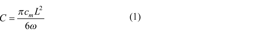
Above, cm is the consistency of the fibers, L is the fiber length, and ω is fiber coarseness. Crowding factor is the average number of fibers in a sphere of the same diameter as the fiber. When the crowding factor exceeds 60, every fiber has on average at least three contacts with other fibers, and the fiber network becomes rigid. 17 In papermaking, the crowding factor is typically 16–60; 18 with higher values flocculation is usually very strong and sheet formation is poor. For this reason, depending on the fiber type, the fiber consistency varies in papermaking between 0.3% and 0.7%. The crowding factor has also been applied to nonwoven webs for investigating the formation of defects. 19
In foam forming, the crowding factor is defined as 12

where
For the 24-mm viscose fibers used here, the foam crowding factor was 1600 with a consistency of 0.3% and air content of 0.7. The crowding factor was thus more than an order of magnitude higher than in papermaking. The flocculation mechanism of long viscose fibers is thus totally different from that of cellulosic fibers or their mixtures with short staple fibers. One reason might be their different surface structures: wood fiber surfaces are covered with fibrils, and when in contact, they can easily form micron-scale bonds. Viscose fibers, in contrast, entangle mainly due to mechanical “spaghetti-like” entanglement.
Effect of air content
Figure 8 shows how SDS concentration, and subsequent foam density, affected the dispersion of fibers. Consistency in this test was 0.30% and mixing time was 120 s. Good fiber dispersion was obtained in a narrow air content range from 0.68 to 0.73 (SDS concentration varied here from 0.15 to 0.17 g/L). The reason for the dramatic drop in sheet quality with increasing air content is currently unclear. One possible explanation is the significant increase in dissipation due to rapidly increasing foam viscosity (see Figure 3(a)). Another possibility is the increase in foam volume with increasing air content (the amount of water was always the same). Both of these decrease the relative volume of high-shear regions due to yield stress, even enabling no-flow regions to be generated. Moreover, for a given fiber bundle, increasing foam volume may decrease the number of passes through the high-shear zone, leaving more unopened bundles in the sheet. Notice that addition of fibers to foam may have some effect on the final air content when mixing conditions, that is, mixing speed and SDS concentration, are kept constant. 20 Figure 9 shows the air content as a function of fiber consistency with the SDS concentration of 0.16 g/L. We see that air content decreases only slightly with increasing fiber consistency.

Dependence of sheet quality on air content and SDS concentration. The red lines indicate the optimal area for air content after mixing.

Air content as a function of fiber consistency. The red arrows show markers that represent two trial points. SDS dosage: 0.16 g/L.
Effect of mixing dynamics
The fiber bundles are broken in the high shear rate regions of the mixing vessel, that is, close to the impeller and especially in the area between the rotating impeller and the vessel bottom. Roping, however, is likely to happen outside this region in turbulent eddies. Eddies are known to generate ropes, especially if their diameter is of the order of the fiber length.21,22
The turbulence level in certain mixing conditions can be estimated using the mixing Reynolds number 23

where ρ is the density of the fluid, N is the impeller rotation speed, D is the impeller diameter, and µ is the fluid viscosity. Despite the diversity of axially agitated mixing geometries, the mixing Reynolds number has been found to be useful in comparing different mixing systems at least when roughly similar mixing geometries and impellers are used. For non-Newtonian fluids, like foams, the viscosity in equation (3) can be estimated from the viscosity-shear-rate curve using the characteristic shear rate,

where the coefficient k generally depends on the mixing geometry and fluid rheology. For our order of magnitude estimate we use the value of k = 13, which was originally derived for flat blade mixers.
25
With the used mixing speed equation (4) gives
Conclusion
We demonstrated with 24-mm viscose fibers that long staple fibers can be dispersed in foam to obtain uniform fiber sheets. Both the fiber length and aspect ratio were significantly higher than those currently used in wet laying. The quality of mixing, however, was sensitive to mixing conditions. With the used fiber type and mixing geometry the optimal air content was 0.7, optimal mixing time was 60 s, and the upper limit of fiber consistency was 0.3%. With other mixing geometries and fibers the optimal conditions are likely to be different and thus need to be optimized separately for each real-life application.
The optimal air content region was narrow for dispersing fibers. Good dispersibility occurred slightly above the foam jamming point (air content 0.64) where the foam has a yield stress and its viscosity is one or even two orders of magnitude higher than for water. As foams are shear-thinning materials, fibers can be easily dispersed, and when the shear rate decreases, viscosity increases considerably, stabilizing the fibers in a dispersed state. Moreover, high viscosity calms the turbulence during mixing, thus decreasing rope-forming. As a result, the formed web obtains excellent uniformity when the foam is removed through the wire.
The crowding factor theory, widely used in papermaking, was found to be non-valid for the evaluation of long fiber flocculation in foam. Excellent fiber dispersion was obtained with crowding factors that were more than an order of magnitude higher than those used in the foam forming of natural cellulosic fibers. The reason behind this needs more study. One possible explanation may be the different bonding of fibers. Wood fiber surfaces are covered with fibrils, and when in contact, they can easily form micron-scale bonds, whereas viscose fibers entangle mainly due to mechanical “spaghetti-like” entanglement.
Optimal mixing time was in our mixing geometry 60 s, during which the fiber logs disintegrated well without significant rope-forming. For industrial applications, the mixing speed could be further increased by a cone or disk refiner, where fiber bundles are added together with the foam before they enter the plate gap, exposing the fiber bundles to high shearing. In this type of arrangement, bundles would stay long enough exposed to high shear stress, the intensity of which could be controlled by changing the plate gap distance, flow speed, or rotation speed. Another possible configuration could be a static cylinder inside a larger, rotating cylinder, with a fiber foam feed at one end and outlet at the other end. The delay could be controlled by cylinder length and flow rate. Whatever the structure, it is important that the vessel and the flow region are free of surface irregularities and roughness, which could initiate rope formation.
Although foam laying is already a 50-year-old method, its potential for nonwovens is still utilized only to a small extent. As environmental and efficiency aspects gain prominence, this is now set to change. Foam forming promises at an industrial level production of uniform webs from staple fibers with clearly lower water volumes and possibly higher machine speeds compared to conventional wet-laid forming. The operating costs of a foam forming process should consequently be lower compared to currently used forming techniques.
Footnotes
Declaration of conflicting interests
The author(s) declared no potential conflicts of interest with respect to the research, authorship, and/or publication of this article.
Funding
The author(s) disclosed receipt of the following financial support for the research, authorship, and/or publication of this article: This work was conducted as part of the Future Fibre Products 2020 (FFP2020) project, which is funded by the European Regional Development Fund (grant number A73089, A73092), VTT Technical Research Centre of Finland Ltd., and 32 industrial partners.