
Abstract
Today, additive manufacturing, also called three-dimensional printing, is used for producing prototypes as well as other products for various industrial sectors. Although this technology is already well established in the automotive, aviation and space travel, building, dental and medical sectors, its integration in the textile and ready-made industry is still in progress. At present, there is a lack of specific application scenarios for the combination of three-dimensional printing and textile materials, apart from fashion and shoe design. Hence, this article presents a digital computer-aided engineering–supported process to manufacture customized orthopaedic devices by three-dimensional printing directly onto a textile fabric. State-of-the-art fabrication methods for orthoses are typically labour intensive. The combination of three-dimensional scanning, computer-aided design modelling and three-dimensional printing onto textile materials open up new possibilities for producing custom-made products. After three-dimensional scanning of a patient’s individual body shape, the surface is prepared for constructing the textile pattern cuts by reverse engineering. The transformation of the designed three-dimensional patterns into two-dimensional is software supported. Additional positioning lines in accordance with specific body measurements are transferred onto the two-dimensional pattern cuts, which are then used as the basis for the design of the three-dimensional printed functional elements. Subsequently, the design is saved in STL (Standard Triangulation/Tessellation Language) file format, prepared by slicing and directly printed onto textile pattern cuts by means of fused deposition modelling. The last manufacturing step involves the assembly of the textile fabric. The proposed process is demonstrated by an example application scenario, thus proving its potential for industrial use in the textile and ready-made industry.
Keywords
Introduction
In recent years, the development of additive manufacturing technologies has enabled a great range of potential applications in different industrial branches. While three-dimensional (3D) printed parts are already used for automotives, aviation or medical purposes, the textile and ready-made industry still lacks specific application examples in the form of functional products that go beyond fashion and shoes. Because additive manufacturing processes offer significant advantages over conventional methods, for example, the tool-less production of complex geometries directly from 3D anatomical data, it is suitable for numerous application fields.
Therefore, this research focuses on the combination of additive manufacturing methods, especially fused deposition modelling (FDM), also known as fused filament fabrication (FFF), with textile materials for the production of novel individualized orthopaedic devices. Functional 3D elements are printed directly onto the textile surface. This process represents a novel textile joining technology as it does not involve conventional joining methods (e.g. sewing, welding, gluing or riveting). As previously addressed by other researchers,1,2 adhesion between polymer and textile is a crucial factor that determines the practicability of multi-material products. To measure and compare resulting adhesion forces, the material combinations are tested using a modified test procedure following the 180° peel test. 3 There is a large variety of parameters affecting adhesion strength, 4 which led to a considerable amount of research activities focused on the investigation of this topic.1,2,5–11 In contrast, this article addresses product development and the computer-aided engineering (CAE)-supported manufacturing process based on the example of a customized orthopaedic device, where a sufficient level of adhesion between functional elements and textile is needed and presumed.
Even though 3D printed orthotics have been available for several years and modifications were made,12–16 the direct combination with textile materials remains an exceptional approach. By combining rigid 3D printed elements with flexible textiles, novel orthopaedic devices can be realized. Such hybrid solutions offer advantageous material properties, for example, skin sensory and thermal comfort, the compression effect of the textile as well as the strength and stiffness of additive manufactured orthotic elements. This article introduces a research project exploring the digital manufacturing process of customized orthopaedic devices, from data acquisition through 3D computer-aided design (CAD) to direct 3D printing onto the textile material. The aim of this article is to demonstrate and evaluate the suitability of additive manufacturing (FDM) for individualized hybrid material products.
Application scenario
The development of a special orthopaedic device must take into account a specific medical indication, due to an injury of the human body locomotor system. This research focuses on an anterior cruciate ligament (ACL) rupture, which is the most frequent type out of all knee injuries (20%). In Germany alone, there are about 35,000 cases every year. In the United States, this number is even higher with 100,000 cases per year. 17 Both cruciate ligaments (anterior and posterior) stabilize the knee joint in the sagittal plane. A ruptured ACL can be identified by the so-called drawer effect, which appears if the tibia shifts anterior relative to the femur. 17 Figure 1 shows the two cruciate ligaments as well as the front drawer test.

Position of the cruciate ligaments in the sagittal plane (left) and front drawer test for ruptured ACL (right).
The operational replacement of the ruptured ACL is recommended especially for athletically active persons. After operational treatment, the patient usually has to wear a rigid-frame orthosis for a duration varying from 6 or 8 weeks to up to 4 months. However, complete recovery takes much longer due to the reduced stability of the knee joint. For this reason, a novel customized orthopaedic device for rehabilitative use is developed to be worn after the rigid-frame orthosis. Typically, the ‘three-point principle’, indicated by red arrows representing simplified forces from the orthosis to the leg in Figure 2, is used to counteract the front drawer effect (or giving way phenomenon) in the sagittal plane. Alternating contact surfaces, extended by an additional arrow (black in Figure 2), counteract the translation of the tibia.
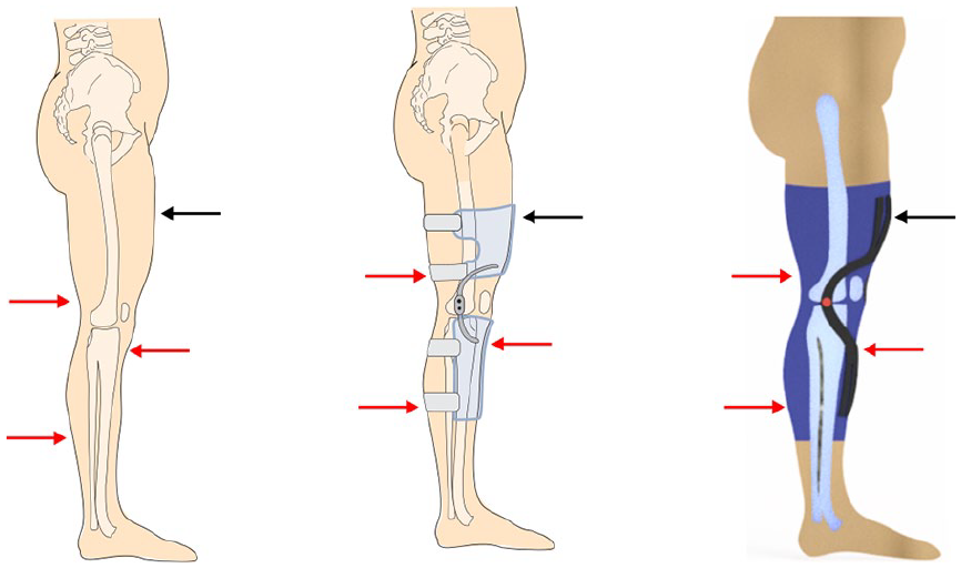
Extended three-point principle of a knee orthosis to prevent instability due to ACL rupture (left and middle: initial principle; 18 right: combination with compression textile).
As a bandage or compression textile itself does not allow for effective lever arms and therefore does not provide a sufficient biomechanical effect, the integration of rigid and stiff elements that cover around two-thirds of the length of the upper and lower leg is required. 18 For this reason, functional elements are constructed and applied directly onto a textile surface.
Method
In accordance with Santos et al., 13 the proposed production process can be divided into the following main stages: 3D scan, 3D modelling or CAD design, and 3D printing.
The 3D scan of the patient captures the individual body shape, which serves as an initial point for the customized product development. A ‘zSnapper’ 3D scanner from ViALUX GmbH, similar to Figure 3, is used for this purpose. The measurement methodology combines the digital light processing (DLP) technology, which represents a micromirror projection from Texas Instruments Inc., 20 with phase-coded photogrammetry. 19

Schematic picture of the 3D scanning process. 19
Figure 4 displays an example of a reverse engineering process for a right leg. After completion of a 360° scan, the ViALUX software generates a 3D model (step 1), resulting in an OBJ data set, which is then opened with the reverse engineering software ‘Geomagic Studio 12’ (newest version: Geomagic Design X). 21 By means of this software, 3D scan data and polygon meshes can be transformed into accurate surface 3D models. Therefore, the scan data are cleaned, smoothed and revised (step 2). The specific body part needed for the product is separated from the full 3D scan. In the presented case, the right leg is used. Specific body measurement lines (e.g. knee, calf and thigh circumference), which typically are used to determine the size of an orthopaedic device, are generated in accordance with the corresponding standard 22 on the surface via cross-section cuts through planes (steps 3 and 4). Then contours on the surface of the polygon model must be recognized. Therefore, previously created lines serve as references for detection and extraction of the contours (step 5). Subsequently, patches are generated inside the contours and processed to ensure the even division of areas inside the contours (step 6). An even finer grid is then automatically constructed inside these patches (step 7). Based on the even division of patches and grids, a more precise areal reconstruction of the polygon model can be achieved. Finally, the nonuniform rational B-spline (NURBS) surface of the polygon model is generated (step 8) by the mathematical approximation of the surfaces formed by the grid and their spline curves and exported to a CAD-compatible file format, such as IGES or STEP, for further processing.

Example reverse engineering process for the right leg of a male patient: (1) 3D scan raw data; (2) repaired 3D scan data; (3) contour lines on the surface; (4) body measurements; (5) defined contour lines; (6) created patches; (7) generated grid and (8) exact spline surface.
Furthermore, the compromise knee pivot point according to Nietert18,23 is measured on the digital model and marked on the surface. The positioning procedure based on the knee width (=100%) in the sagittal plane is illustrated in Figure 5. A precisely and individually placed pivot point for each person is mandatory to enable the correct function of the orthopaedic device. Otherwise, the products’ effect would be counterproductive for rehabilitation or might even damage the knee joint, which must be avoided.

Determination of the compromise knee pivot point (left) 18 and flattening of the textile pattern cut (middle: right leg with region and supporting lines in 3D; right: flattened 2D pattern cut positioned in knitting directions).
Although the usage of software for reverse engineering such as ‘Geomagic’ is not mandatory as 3D scan data can be directly processed, working on CAD surfaces is still more convenient.
In a next step, the software ‘DesignConcept’ from Lectra 24 is used to draw design and sewing lines in 3D. The boundaries of the textile bandage are drawn directly onto the leg surface based on the described design guideline (two-thirds of the length of the upper and lower leg). Moreover, a knee cutout and a sewing line on the back are added. For 3D printing onto a flat knitted textile surface, a sewing line is necessary to complete the orthopaedic device. The design lines of the functional elements, which later will be 3D printed, are then also drawn directly onto the leg surface. Therefore, the extended ‘three-point principle’ and the compromise knee pivot point must be considered to ensure the desired impact against the front drawer effect. According to the middle image of Figure 2, two stiffening elements are placed at the front side of the leg. The compression textile replaces the normally used straps for orthosis. After drawing the positioning and design lines, a mesh (so-called region), consisting of triangles with a defined side length, is generated. The middle picture of Figure 5 shows the 3D model of a right leg with the body measurement lines in the perimeter direction (e.g. calf circumference) in red colour, the design outlines in black, the compromise knee pivot point (blue line with black circle) and the region in light blue.
The developed pattern design or region is then flattened from 3D to two-dimensional (2D) by a software-supported process (Figure 5, right) using ‘DesignConcept’, meaning that the triangle mesh (region) is laid down flat. With respect to the knitting direction of the textile and therefore its compression effect, the cutting pattern is positioned in the course stitch row direction (CSRD) and the knitting wale direction (KWD). The elastane inlay threads, which support the compression effect, are oriented in the CSRD. Therefore, the perimeter direction needs to be positioned along the CSRD as well. In addition, the 3D lines are transferred onto the 2D pattern, which later serve as construction outlines for the functional elements.
By developing the textile design directly in 3D, the resulting 2D pattern is on the body scale. To realize the defined pressure of approximately 2.4 kPa (=18 mmHg), which corresponds to the lower limit value of compression class 1, 25 the pattern cut is scaled down using simulation tools. Thus, the knitted fabric’s tensile elastic behaviour is tested on a ‘Z 2.5’ tensile testing machine from ZwickRoell GmbH & Co. KG according to DIN 53835-14. 26 The left part of Figure 6 shows the resulting force–strain diagram in CSRD for three textile samples. The flat knitted textile fabric consists of 75% polyamide (PA) 6.6, 18% raw rubber and 7% elastane. It is 2.69 mm thick and has a weight per unit area of approximately 850 g/m2. To implement the measured material characteristics into the software, an averaged linear reference curve (purple curve on the right-hand side of Figure 6) is calculated based on the last cycles with increasing force and elongation. Due to a permanent elongation in previous testing cycles, a migration of the zero point at the force value of 0 N has occurred in all samples, meaning that even without the application of force the fabric already shows a low elongation. In order to exclude the influence of residual elongation from previous cycles, the reference curve (purple) is shifted to the zero point resulting in the final linear material curve (green curve on the right-hand side of Figure 6). The measured force refers to the width (60 mm) of the sample holders used for testing.
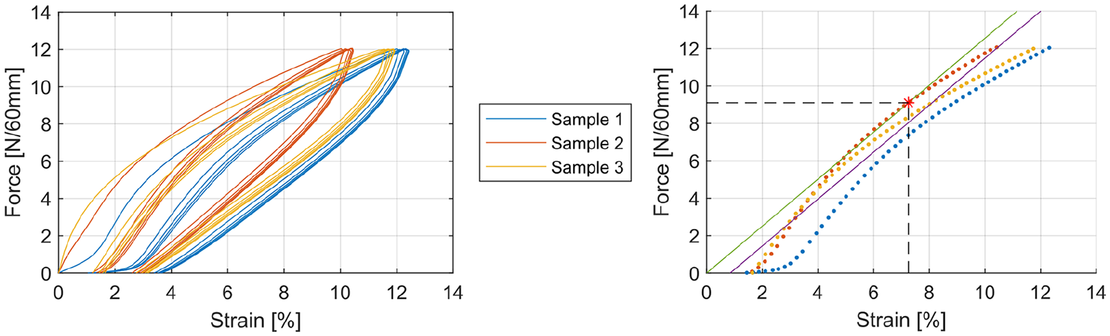
Force–strain diagram of knitted textile fabric in the CSRD (left: multi-cyclical testing; right: the last increase in elongation for each sample and approximated linear material curve).
The assigned material characteristics allow for a circumferential (CSRD) pressure simulation of different scaling factors (Figure 6) using ‘DesignConcept’. The simulated pressure peaks visible in Figure 7, especially in the knee area, are attributed to small curvature radii originating from underlying skeletal structures. As the green-coloured area represents the target pressure value of 2.4 kPa, a scaling factor of approximately ‒7.5% leads to the best overall distribution according to the optical analysis displayed in Figure 7.

Comparison of circumferential pressure analysis of a knitted textile fabric with different scaling factors in the CSRD.
Typically, the Laplace equation, originally described by Thomas Young and Pierre Simon de Laplace in 1805, 27 is used to calculate the localized static pressure of compression textiles at a given point. The modified Laplace equation 28 is given as follows
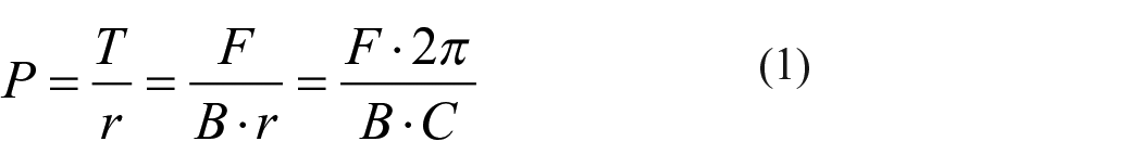
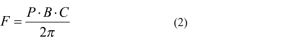
with pressure P (Pa), tension T (N/m), radius r (m), compression force F (N), width B (m) and circumference C (m). The averaged force required to realize 2.4 kPa of pressure yields a force value of 9.1 N (see Table 1), which is related to a corresponding textile elongation in the CSRD in accordance with the tested elastic behaviour of the knitted fabric (red point on the right diagram of Figure 6). As a result, a circumferential scaling in the CSRD of ‒7.25% is required in the case of the selected knitted fabric to achieve the specified compression effect according to the calculation carried out.
Body measurements and calculated forces required for compression.

By means of the direct knitting of custom-made textile fabrics, the compression effect distribution along the leg can be adjusted depending on individual body circumferences to realize the exact force needed for every individual body measurement. However, textile yard ware is used for this work, so the averaged force is applied.
The scaled textile 2D pattern is exported as a DXF file, which is used to prepare the textile cut. The unscaled 2D pattern with all design and supporting lines serves as the starting point for the 3D construction of functional elements.
Opening the DXF file in a 3D CAD software, for example, ‘SolidWorks’, ‘Fusion 360’, ‘Rhino’ or similar software solutions, provides the outlines and position information for the design of functional elements. The elements are constructed in 3D by taking into account the following design guidelines.
According to expert discussions with orthopaedic technicians, a maximum element thickness of 5 mm should not be exceeded. Otherwise, these elements would protrude, thus potentially rubbing against other body parts, which might cause an unpleasant sensation for the patient, particularly on the inside of the leg. Thus, the geometric models are designed with spline modelled curves for smooth edges. Thickness variations along the component follow the needed bending ability (thinner for bending, thicker for stiffening) and create an organic appearance.
The required stiffnesses can be determined by simulation. The material selection (short or continuous fibre reinforcement) and construction of the elements (thickness, 3D printing parameters) are performed in consideration of the specific bending stiffness of a certain material, which is determined by means of testing (see Figure 10 and Table 2). The required thickness of the 3D printed elements depends on the selected reinforcement material. In order not to exceed the scope of this article, the simulation-based design of 3D printed functional elements will not be addressed in the following sections.
3D printing parameters of four-point bending class 1 test specimens, bending modulus Ef and maximum bending stress σfm.

PETG: polyethylene terephthalate glycol; PETG-CF: carbon short fibre–reinforced polyethylene terephthalate glycol.
3D printing in this case can be aptly described as 2½D printing as functional elements are applied onto a flat textile piece; therefore, the final bending and curvature of the leg must be considered at the design stage. Due to the required adaptation of rigid elements to the leg curvature, elements positioned in the perimeter direction of the knee are designed to be more flexible. Stiffening elements are positioned along the longitudinal direction of the leg (parallel to the knee centre line), where less bending occurs.
Furthermore, the knee joint is designed as a pin-and-ring connection using the axis of rotation calculated according to Nietert. While the lower leg elements mainly serve to secure the tibia, the connection to the upper leg elements allows for the force flow. Apart from this, the textile component of the upper part provides slip resistance due to the compression effect acting on the upper leg. It should be noted that semi-finished metal joint elements can be integrated instead of 3D printed joints due to loads frequently affecting this part. The proposed design includes a 3D printed joint to demonstrate the possibilities of additive manufacturing.
Laterally expanding elements are located on the sides in order to prevent the textile bandage from slipping. Figure 8 shows the proposed design, which is exported as an STL file, to be further processed with a slicing software.

Position of the functional 3D CAD elements on the textile pattern cut.
In addition, an offset element, which fulfils two tasks, is constructed. First, it serves as a positioning aid for the textile fabric. It can be seen from Figure 8 that it is placed inside the kneecap cut forming a cross, which helps with the correct alignment of the textile pattern cut and prevent unintentional rotation. Second, it generates the z-offset (1.6 mm height) required for the first layer printed onto the textile (layer from 1.6 to 1.8 mm) to achieve increased adhesion. That way, the sufficient height allows not just for the correct positioning of the textile by applying it to the edges of the offset element but also for the next layer being printed ‘into’ the textile surface structure.
Since the model is not to be produced on the print bed of a 3D printer, but on a textile, adjustments are made to the CAD model and the resulting print files. The adaptation of the model is based on material thickness. The distance between the printing nozzle and the textile surface is known to be a parameter significantly affecting adhesion.4,6,7,29 A minimum distance or even printing ‘into’ the textile is desired to increase adhesion. Preliminary trials regarding the selected textile fabric with a thickness of 2.69 mm result in a minimum processable z-offset height of 1.6 mm. Once 3D printing of the offset element is completed, the process is paused to insert the textile. Subsequently, the printing process is resumed and the first adhesive layer is printed into the textile. While compressing the textile through the nozzle, the deposited thermoplastic material impregnates the textile surface to develop a form-locking adhesion. After finishing the 3D print of the first adhesive layer, the distance between the nozzle and textile must be increased due to the counterforce generated by the expanding textile, which now has a more solid surface where the material was deposited. Printing errors could occur, which can be avoided by the removal of certain layers for the corresponding textile thickness. Hence, a partial relaxation of the textile fabric can be ensured. The suitable distance between the nozzle and the adhesive layer enables a clean 3D print. In summary, the design needs to be extruded straight down for 1.0 mm (five layers, of which four will be deleted afterwards in the G-code) and an offset element of 1.6 mm height must be constructed beneath it. A schematic illustration of the model adjustment based on a layer height of 0.2 mm is shown in Figure 9.
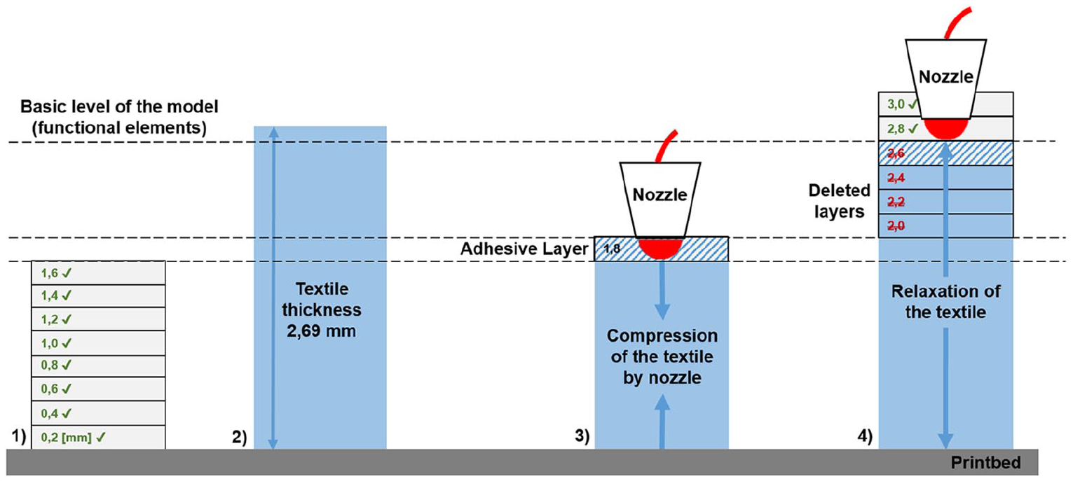
Steps for 3D printing onto a textile: (1) offset object with 1.6 mm height; (2) textile insertion; (3) printing directly onto the textile and (4) z-offset of the nozzle by deleting layers and continued 3D printing.
The machine data for the 3D printer is generated in the slicing software ‘Slic3r PE’, which follows an open source approach. The generated STL file is therefore imported and different printing parameters, such as infill pattern and percentage, number of outer contours, bottom and roof layers, extruder and print bed temperature, are set. By adjusting these parameters, the mechanical properties are modified to suit the desired application scenario.
By means of this software, the entire model is sliced into single layers. The G-code format is used for the control of computer numerical control (CNC) machines and describes coordinates as well as machine control commands. Furthermore, the generated G-code file must be edited to insert a pause for textile insertion and delete selected layers before 3D printing. To modify the G-code, a simple text editor can be used. In the case of this research project, the ‘M601’ pause command is inserted in the G-code prior to printing of the adhesive layer, and layers from 2.0 to 2.6 mm are deleted as shown in Figure 9.
The 3D printer ‘Prusa i3 MK3’ from Prusa Research a.s. with a nozzle diameter of 0.4 mm and the printing material ‘CarbonFil’ 1.75-mm filament from FormFutura, which is a polyethylene terephthalate glycol (PETG) blend reinforced with 20% carbon short fibres, 30 are selected for this research.
To extend the performance capacity of FDM-produced parts, additional high-performance fibres (carbon, glass, aramid) can be integrated. There are two types of fibres that can be employed to reinforce FDM parts: short and continuous fibres. While short fibres can be processed easily using a special commercially available material (pre-blended), continuous fibres require an additional cutting unit and a special slicing software, for example, when working with ‘MarkTwo’ 31 and ‘Composer’ 32 3D printers. The structural–mechanical properties (bending resistance) of components can be enhanced and the weight or component thickness can be reduced by means of short fibre reinforcement compared to the identical thermoplastic material without any reinforcement. As an example, a minimum of five class 1 specimens are tested with a ‘Z100’ testing machine from ZwickRoell GmbH & Co. KG according to DIN EN ISO 14125. 33 Figure 10 shows the averaged stress–strain curves of the 3D printed test specimens for pure PETG (FormFutura ‘HDglass’ 34 ) and PETG with short carbon fibres (CFs) in dependence of the respective layer thickness.

Averaged four-point bending test results of 3D printed specimens with different layer thicknesses.
All 3D printing parameters and the corresponding results are given in Table 2. By adding 20% carbon short fibres to the PETG material, the bending modulus value Ef is more than doubled and the maximum bending stress σfm is increased by approximately 30%.
As the textile 2D pattern cut is scaled along the CSRD and the functional 3D printing elements are designed at a body scale, a pre-stretched textile must be used for printing. For this purpose, the textile is positioned on the print bed with the help of the offset element and a defined elongation (7.25%) using fold-back clamps and water-soluble glue for fixation. Adhesion is not significantly influenced by printing onto a pre-stretched textile compared to printing onto a textile in its initial length.35,36 Due to the transverse contraction of the knitted textile under pre-stress, the height of the textile may change, so that the z-offset value must be adjusted accordingly. The fixation of the textile fabric during the additive manufacturing process is displayed in Figure 11.

Fixation of the textile fabric for 3D printing functional elements (left: usage of fold-back clamps accompanied by water-soluble glue; right: 3D CAD construction of possible clamping devices).
Due to the limited building volume of the used ‘Prusa i3 Mk3’ 3D printer, the orthopaedic device was separated in two parts/halves, corresponding with the upper and lower leg. Therefore, the textile pattern cut is divided along the knee axis of rotation (CSRD). Since this partition is only due to hardware limitations, another 3D printer with a larger build volume or a special fabricated 3D printer would allow for a one-piece manufacturing process.
The rigid elements of the upper and lower leg can be connected by means of both 3D printed or purchased semi-finished joint elements. The additive manufacturing of special connection elements can support the use of high-strength semi-finished joint components.
Upon successful completion of the 3D printing process, both parts (upper and lower leg) are sewn together, the bandage is closed by sewing and edges are trimmed.
Results and discussion
The entire process from 3D scanning of the individual body surface to the ready-made product is carried out and documented to establish an example process. Based on this CAE-supported process chain, a novel customized orthopaedic device (Figure 12) is developed by the direct application of 3D printed functional elements onto a textile fabric. Hence, a flexible compression textile is joined with rigid stiffening elements, thus combining skin sensory comfort, compression effect as well as light and stable joint guidance.

3D printed novel customized orthopaedic device produced by printing of carbon short fibre–reinforced PETG directly onto a knitted textile fabric.
The orthopaedic device shown in Figure 12 is manufactured by the CAE-supported process, which is shown in Figure 13 including individual file formats used in each step. Hence, each process step can be investigated, although the simulation and optimization of the rigid stiffening element design, especially when using continuous fibre reinforcement, will be explored in detail in future publications.

Process chain for the manufacturing of novel customized orthopaedic devices by 3D printing directly onto a textile fabric.
Based on the 3D scan of a patient, reverse engineering is used to access the surface of the specified body part and mark relevant body measurements. In a next step, the textile component is designed in 3D and flattened into 2D pattern cuts by suitable software. The desired level of compression is achieved by consideration of material characteristics (stress–strain properties of the textile fabric) and scaling of the 2D pattern. Orientation points and position or body measurement lines can be transferred from 3D to 2D. They are used to design the functional elements (e.g. stiffening, joint) in the 3D CAD program. High-performance fibres are processed for the specific design of mechanical characteristics. After file preparation (slicing, G-code modification), additive manufacturing directly onto the textile surface is performed. After a final finishing is applied to the product, the individual orthopaedic device is complete.
The 3D scanning method can be improved through the use of optical markers and a related software that automatically marks certain body dimensions. Thus, data acquisition would be simplified and the CAE-supported process can be accelerated.
However, the additive manufacturing onto a flat textile surface limits the freedom of design as the final body curvature needs to be addressed at any product development stage. A potential solution involves direct 3D printing onto a textile placed on a counter form with robotic equipment so that the manufacturing process becomes more complex and complicated to handle, but limitations due to 2½D printing could be overcome.
The use of pre-fabricated parametric templates of the functional elements that can be adapted to specific patient body dimensions will shorten production cycles. In addition, the automation of the process chain would also lead to accelerated production times.
Orthopaedic devices employed as medical products require certification by authorities. Therefore, further research activities addressing quality and reproducibility testing are needed to investigate the reliability requirements for standardized industrial processes.
Conclusion
The presented CAE-supported process offers a great potential for customized products (lot size 1), such as orthopaedic devices, by the combination of additive manufacturing and textile materials. The aim is to enable the fast supply of medical devices with improved fitting, resulting in higher patient compliance.
The integration of additive manufacturing into the textile and ready-made industry offers a wide range of possibilities for the production of innovative multi-material products. In the field of orthopaedic aids, new types of products can be manufactured according to individual customer requirements. Flexible soft textile materials are combined with rigid and stiff additive manufactured functional elements by direct application as an alternative joining method. In addition, high-performance fibres, such as carbon or glass, can be processed to realize lightweight construction potentials and to adjust the structural–mechanical properties to suit the desired application. In the near future, the continuous CAE-supported process chain developed will enable experts to quickly supply patients with individualized orthopaedic aids. In addition to novel designs, rapid implementation of design adjustments and an improved fit based on 3D scans, patient compliance is to be increased. However, the presented concept has to go through further development and testing before supporting end users.
Footnotes
Declaration of conflicting interests
The author(s) declared no potential conflicts of interest with respect to the research, authorship and/or publication of this article.
Funding
The authors disclosed receipt of the following financial support for the research, authorship, and/or publication of this article: The IGF research project 19757 BR of the Forschungsvereinigung Forschungskuratorium Textil e. V. is funded through the AiF within the program for supporting the “Industrielle Gemeinschaftsforschung (IGF)” from funds of the Federal Ministry for Economic Affairs and Energy (BMWi) by a resolution of the German Bundestag. Open Access Funding by the Publication Fund of the TU Dresden.