
Abstract
Whether for producing prototypes or functional parts by additive manufacturing, the fused deposition modeling is the most commonly used technique. Nevertheless, not only the hobbyist but also the industrial three-dimensional printers produce parts that suffer from anisotropy in their mechanical properties imposing important limitations on the strength of the manufactured piece. The aim of this work is to propose a strategy for determining the optimal build surface orientation of three-dimensional truss-like structures manufactured using fused deposition modeling. This can be achieved by minimizing the norm of the dot products of the normal direction of the deposition plane (build surface plane) and the directions of the tensile forces. Since three-dimensional trusses are subjected to tensile forces in different directions, a multi-objective cost function was proposed. Moreover, these structures might present rotational symmetry, which should be considered as design constraints. In this work, two three-dimensional truss-like structures were investigated. The nature of the optimization is case dependent and solvers were selected accordingly. Experimental campaigns were carried out for evaluating the specimens manufactured using fused deposition modeling. It could be concluded that higher yield tensile strength could be achieved by adopting the optimal deposition plane. This result demonstrates the applicability of optimization techniques for improving additive manufacturing results.
Keywords
Introduction
Fused deposition modeling (FDM) is the most common additive manufacturing (AM) technique. It is widely used for manufacturing not only prototypes, but also functional products.1–4 Thereby, the mechanical strength of the parts obtained by AM should be an important aspect during their design and manufacturing as discussed in Griffiths et al. 5 and Huang and Singamneni. 6 Several strategies to improve the strength of the parts using FDM can be found in the literature, such as the use of high-strength resins, 7 carbon fiber–embedded printed structures, 8 resin infiltration, 9 among others. Moreover, a proper selection of the process parameters can improve the strength of the printed devices. For instance, Griffiths et al. 5 exploited design of experiments’ techniques for optimizing the tensile and notched bending properties of the parts obtained by AM.
The material deposition of FDM is made using successive layers, as illustrated in Figure 1. This strategy yields pieces that suffer from strong anisotropy as experimentally verified by Ahn et al. 10 and by Upadhyay et al. 11 In this way, the deposition orientation plays an important role on the strength of the manufactured pieces by FDM.12,13 Taufik and Jain 13 presented a comprehensive review on the role of the build orientation in layered manufacturing. In fact, a good choice on the deposition orientation can reduce the building time,14–16 decrease the surface roughness,15–17 reduce the required support (volume and area) minimizing the post-machining processes,18,19 increase the mechanical strength,20,21 improve mechanical reliability levels, 22 reduce costs, 23 among others.
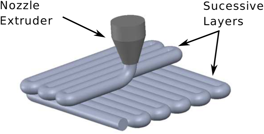
Successive layers during the material deposition.
It is a fact that a large number of works have proposed strategies for reducing the post-processing by selecting an optimal deposition strategy. For instance, multi-criteria optimization problems were posed by Pandey et al. 14 and Ghorpade et al. 16 The main conclusion of these works was that both surface finishing and building time criteria could be optimized simultaneously by a proper selection of the deposition plane. On the other hand, a smaller number of works have proposed strategies for improving the strength of the printed parts by selecting an optimal build surface plane orientation, among them.18,20,21 Experimental tests were conducted by Villalpando et al. 18 and Gurrala and Regalla 20 using not only different deposition orientations but also different material usages and build time. Both works exploited meta-modeling techniques for deriving the relation between the design and objective spaces. For instance, the relations between the internal structural configuration, the material usage, the build time and the strength of the part were derived by Villalpando et al., 18 and the relation between the deposition orientation and the measured strength was constructed using analysis of variance by Gurrala and Regalla. 20 Finally, optimization techniques were successfully exploited using these relations. Lovo et al. 21 investigated a strategy for selecting a proper build surface plane for a three-dimensional (3D) truss element manufactured using FDM via an optimization problem. These preliminary results, discussed in Lovo et al., 21 demonstrated the potential of the use optimization techniques for addressing this issue. The impact of deposition orientation on the mechanical reliability was assessed by Keles et al. 22 It was demonstrated that the Weibull analysis provides a practical design criterion for assuring specific mechanical reliability levels. It is a fact that optimal deposition orientation is strongly dependent on the structure under study. This might be the reason for the lack of works deriving a straightforward relation between the deposition orientation and the mechanical strength of the parts.
In this work, a strategy for finding a proper deposition plane for 3D truss-like structures manufactured using FDM is proposed. This strategy, which is an extension of the one proposed by Lovo et al., 21 mathematically describes a multi-objective optimization problem that aims to find the best deposition plane orientation that maximizes the mechanical strength of 3D truss-like structures. Spite of their importance, other aspects as build time, support material volume and roughness were not considered in this multi-objective problem since the objective of this work was the investigation of the impact of the build surface plane orientation on the mechanical strength of the studied parts. Two case studies are investigated: (1) a 3D truss element and (2) a simple 3D truss. The nature of the optimization problem is case dependent. The former could be formulated as a convex optimization problem, while the latter yielded a non-convex optimization problem. A convex optimization problem presents a single optimal solution (the global optimum), while a non-convex optimization problem might present several optimal solutions (local optima). Usually, convex problems are easier to solve. 24 Specimens of both case studies using the optimal and non-optimal deposition planes were also manufactured using acrylonitrile–butadiene–styrene (ABS) P430. According to Sarvakis et al., 25 the yield tensile strength of the ABS P430 varies between 29 and 32 MPa for one-line specimens manufactured using FDM with a deposition orientation perpendicular to the specimen orientation and between 14 and 16 MPa for one-line specimens manufactured using FDM with a deposition orientation in line to the specimen orientation. In this work, these specimens were manufactured using a Dimension Elite 3D printer developed by Stratasys. The temperatures of the build chamber and the build platform were controlled. Moreover, this 3D printer presents high accuracy standards and employs specific materials for the parts’ support. Due to these features, the parts presented high dimensional precision. Experimental campaigns for evaluating these parts demonstrated that higher yield tensile strength could be achieved by adopting the optimal deposition plane.
The rest of the manuscript is organized as follows. First, the proposed methodology for selecting the optimal deposition plane for 3D truss-like structures manufactured using FDM is described. This methodology is exploited for selecting the optimal deposition plane of a 3D truss element and of a simple 3D truss. The investigation of both case studies contains the description of the structure under study, the mathematical formulation of the optimization problem and the discussion of the experimental results. The experimental results show a comparison between tensile tests of the manufactured specimens by AM using the optimal and non-optimal deposition planes. Finally, conclusions are drawn.
Methodology
The optimal tensile strength can be guaranteed if the direction of the filaments is in line with the direction of the tensile forces. In this way, a strategy for selecting a proper deposition plane is required. In this work, the angles between the directions of the tensile forces and the direction of the build surface plane are minimized via an optimization problem.
First, the optimization problem requires the mathematical description of the direction of the tensile forces. An important hypothesis in this work is that the 3D printed truss-like structures behave as a theoretical truss. So, the description of the direction of the tensile forces can be done by describing the direction of the truss members,

where
Finally, the angles between the tensile force directions and the build orientation,
where
Some 3D truss-like structures may present rotational symmetry. Rotational symmetry is a geometrical property that a shape may have when it presents the same shape after some rotation smaller than
The aforementioned strategy for finding a proper deposition plane for 3D truss-like structures manufactured using FDM is exploited for selecting the deposition plane of two case studies: (1) a 3D truss element and (2) a simple 3D truss structure. The 3D truss element presents rotational symmetry of order 3 while the simple 3D truss structure presents no rotational symmetry. These case studies are treated in the following sections.
Case study 1: the 3D truss element
In this section, case study 1 is exploited. First, the case study is described. Second, the optimization problem for finding a proper deposition plane is mathematically posed according to the proposed methodology. Finally, experimental results are presented and discussed.
Description of the case study
The 3D truss element under study is a functional part that holds a digital camera used in a drone, as depicted in Figure 2. Due to its functionality, such part should be as light as possible. Figure 3(a) and (b) depicts a CAD view of the 3D truss element and a scheme of the tensile forces action on its members during its service. As illustrated by these figures, three members are subjected to a maximum traction force of 14 N and one component is subjected to a maximum traction force of 30 N. This 3D truss-like structure presents rotational symmetry of order 3, as illustrated in Figure 3(a). The geometry of the device should be kept constant due to its functionality. A usual deposition plane, with a build orientation perpendicular to the thicker component, is illustrated in Figure 4(a). This choice guarantees the maximum tensile strength for the thicker component of this case study.
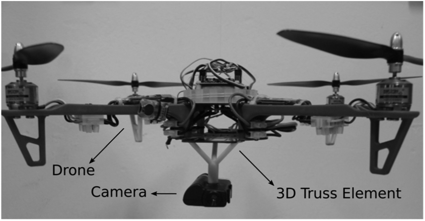
The drone, the camera and the 3D truss element.
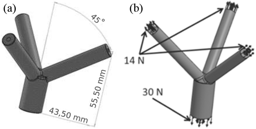
Case study 1: (a) CAD of the 3D truss element and (b) the tensile forces acting on the 3D truss element.
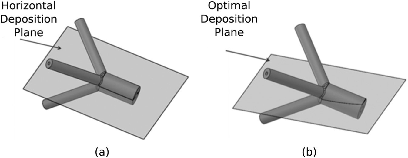
The build surface planes: (a) a usual deposition plane and (b) the optimal deposition plane.
The optimal deposition plane
According to Figure 3, one can note that the different directions of the tensile forces impose a design challenge on the selection of the orientation of the deposition plane for this printed device. The optimal deposition plane is found by exploiting the proposed methodology. In this way, the description of the direction of the members of the 3D truss element should be mathematically done. In this way, three vectors

The 3D truss under study presents rotational symmetry of order 3. In this way, geometrical constraints should be imposed for guaranteeing that the thinner elements present the same mechanical strength. The first one imposes that the angles
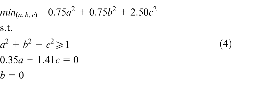
In this optimization problem, the cost function and the inequality constraint are quadratic and the equality constraints are linear. This is a Quadratically Constrained Quadratic Program (QCQP).
26
This problem can be easily solved by non-linear solvers such as Sequential Quadratic Programming (SQP).
26
An alternative is to consider only linear constraints. This alternative optimization problem is composed of convex functions and can be solved using dedicated solvers for convex optimization problems.
24
By exploiting this alternative, one can solve this problem using Quadratic Programming (QP).
26
This can be done by considering the norm-1 instead of norm-2 of the vector that is furnishing the normal direction of the deposition plane,
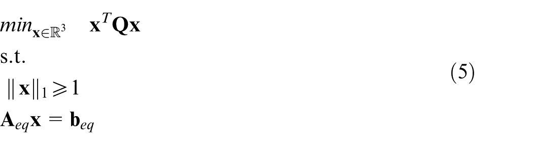
where
In this article, the QCQP was solved using the SQP algorithm, that is available in MATLAB, and the QP was solved using the Interior-Point algorithm that is implemented in SeDuMi. 28 For the QP, the modeling layer YALMIP 30 was employed in the MATLAB environment. Both approaches yielded the same solution when normalized

The optimal deposition plane is illustrated in Figure 4(b).
Experimental results and discussion
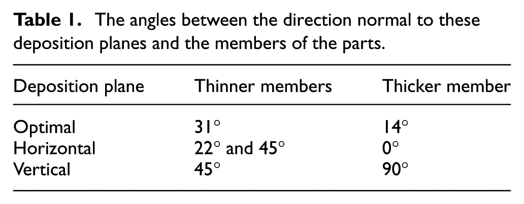
An experimental campaign was carried out in order to validate the proposed methodology and numerical results. In order to do that, three 3D truss elements were compared regarding their mechanical strength. They were manufactured by FDM using three different deposition planes: (1) the optimal, (2) the horizontal and (3) the vertical deposition planes. The non-optimal deposition planes were selected according to usual choices. In fact, the selection of the horizontal deposition plane, illustrated in Figure 4(a), guarantees the maximum tensile strength of the thicker member of this 3D truss element. The angles between the direction to these deposition planes and the members of the 3D truss-like structures are given in Table 1. The printed devices are depicted in Figure 5.
The angles between the direction normal to these deposition planes and the members of the parts.
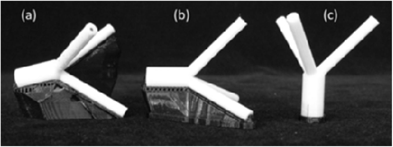
The printed 3D truss elements manufactured using (a) the optimal, (b) the horizontal and (c) the vertical deposition planes.
The evaluation of the mechanical strength of the 3D truss elements would require the use of dedicated devices to hold the printed elements in the testing machine. The design of these devices can be a challenge task since a correct load distribution should be done. In order to avoid errors in the load distribution, tensile specimens for each member of the 3D truss elements were manufactured according to the angles described in Table 1. These specimens were also manufactured using the Dimension Elite 3D printer. For sake of illustration, the specimen of the thicker element of the 3D truss manufactured using the optimal deposition plane is shown in Figure 6.
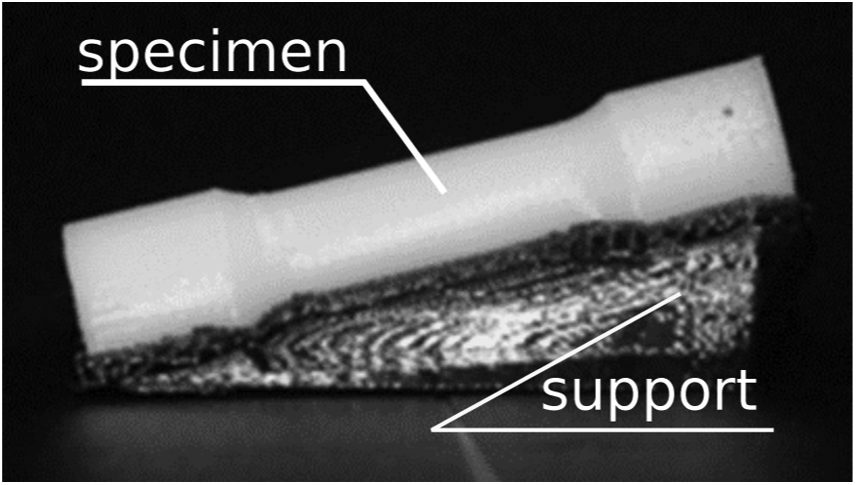
A specimen and its support.
A tensile testing was carried out using a universal testing machine Bionix and a load cell of 15 kN manufactured and commercialized by MTS, depicted in Figure 7(a). This procedure followed the ASTM D638-14 Standard Test Method for Tensile Properties of Plastics. A specimen is shown under testing in Figure 7(b) and the tested specimens are illustrated in Figure 8. Figure 9 illustrates the yield tensile strength that each member of the 3D truss elements can hold according to the experimental tests. One can conclude that by selecting the optimal deposition plane, the part can support up to 25 MPa; while by selecting the horizontal and the vertical planes, the printed device can support up to 20 and 16 MPa, respectively. In this way, the optimal selection of the deposition plane guaranteed an increase in the tensile strength up to 25% and 57% compared to the horizontal and vertical deposition planes, respectively. This result demonstrates that the mechanical strength of this part can be largely improved if the optimal deposition plane is selected.
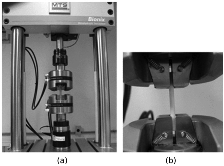
Experimental campaign for case study 1: (a) the MTS testing machine and (b) a specimen under testing.
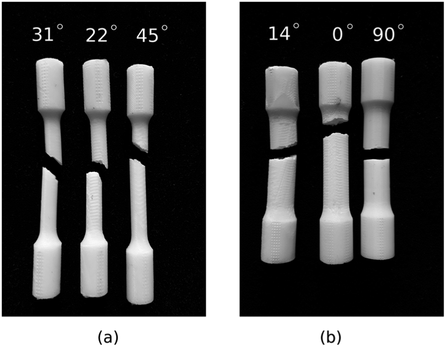
The specimens after the tensile testing: (a) the thinner members and (b) the thicker members.
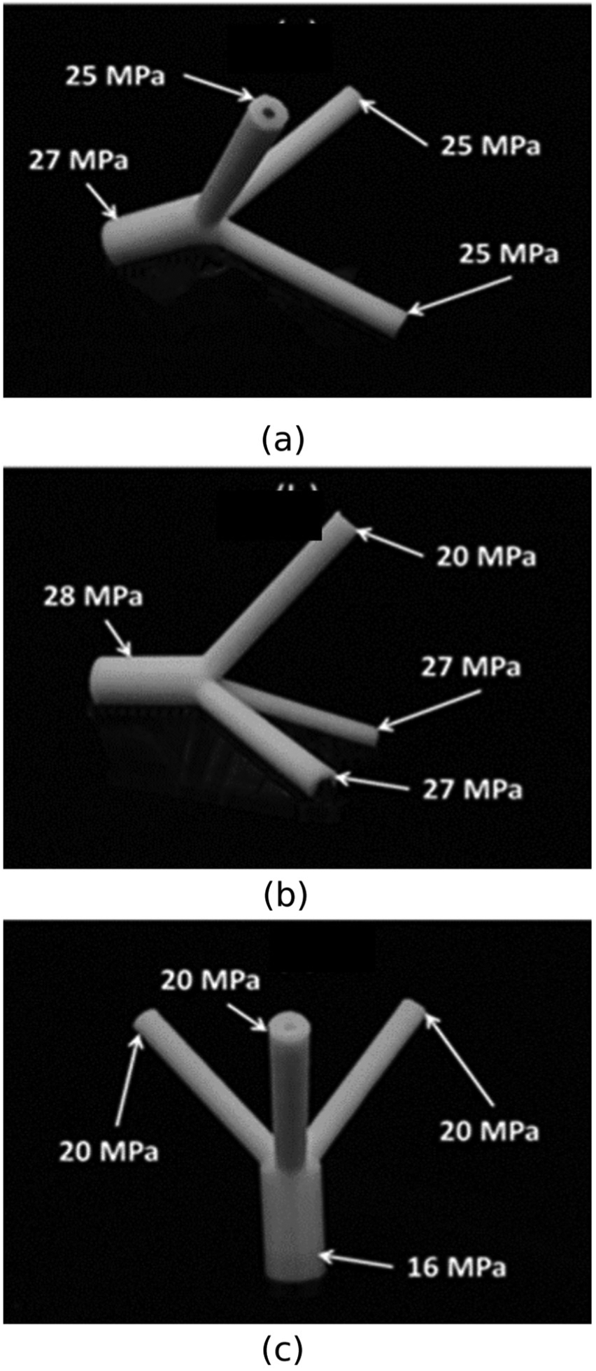
Experimental values for the yield tensile strength for different deposition planes: (a) optimal, (b) horizontal and (c) vertical.
Due to the importance of reducing the use of support material,18,19 it is important to highlight that the option that requires the smallest amount of support material for case study 1 is the non-optimal vertical deposition plane, as illustrated in Figure 5. This demonstrates that there might be a trade-off between the optimal deposition plane for minimizing the material support and for maximizing the tensile strength. This trade-off is highly dependent on the geometry of the case study. In this way, a general conclusion is not straightforward.
Case study 2: a simple 3D truss
In this section, case study 2 is exploited. Similarly, the case study is first introduced. Then, the optimization problem and the experimental results are presented and discussed.
Description of the case study
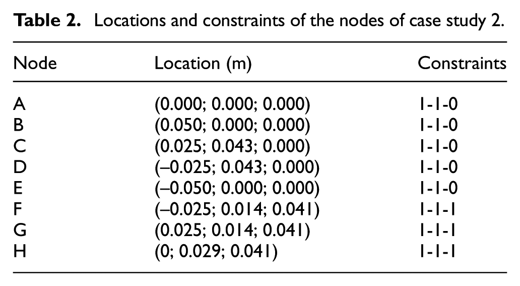
The simple 3D truss and the adopted coordinate system are illustrated in Figure 10. This simple structure is composed of 8 nodes and 19 members. The locations and constraints of the nodes are given in Table 2. The constraints are described by three numbers regarding the degree of freedom in the x-, y- and z-directions, respectively. These numbers may be 1 to a constrained degree of freedom or 0 to a free one. In this way, the boundary conditions (constraints) of node A are described by 1-1-0, which means that the node A can only move in the z-direction.
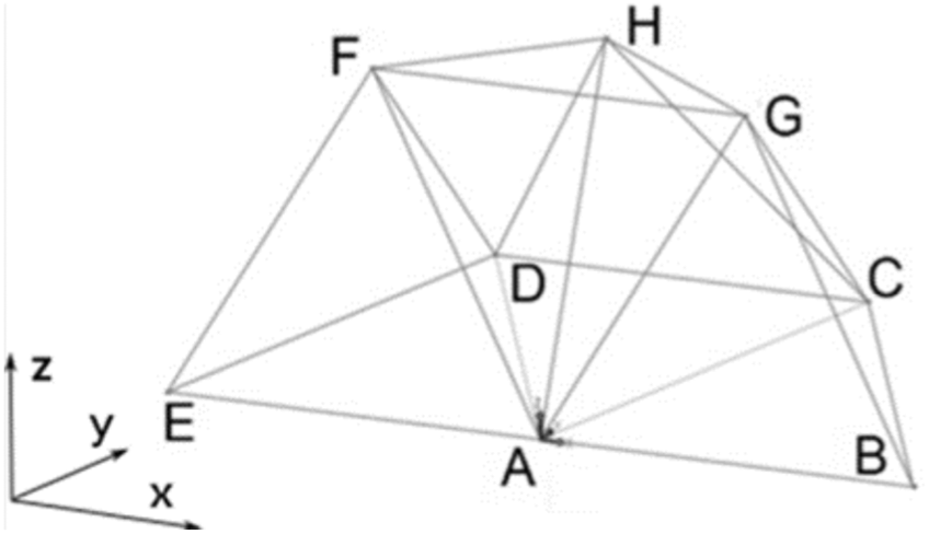
Case study 2: the simple 3D truss.
Locations and constraints of the nodes of case study 2.
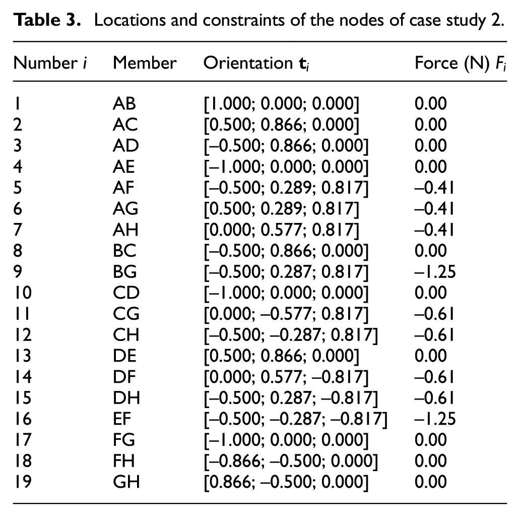
The orientation of each member is described in Table 3. The nodes A, B, C, D and E are subjected to a force of
Locations and constraints of the nodes of case study 2.
The optimal deposition plane
According to Figure 10 and Table 3, one can note that the selection of the orientation of the deposition plane is not straightforward due to the different directions of the tensile forces. In this work, the optimal deposition plane is found by exploiting the proposed optimization problem. The orientations of the members of the 3D truss structure,

This 3D truss presents no rotational symmetry, so the geometrical constraints should not be imposed. In order to avoid the null solution, a constraint regarding the norm of the vector

This optimization problem can be solved using the SQP algorithm 26 that is available at MATLAB, yielding the following normalized solution

which is a vector normal to the optimal deposition plane.
Experimental results and discussion
An experimental campaign was carried out in order to assess the benefits of selecting a proper deposition plane. In order to do that, three simple 3D trusses were manufactured using different deposition planes: the optimal deposition plane (see equation (10)) and two non-optimal deposition planes as depicted in Figure 11. The non-optimal deposition planes were selected according to the coordinate reference system, depicted in Figure 10. Five specimens were manufactured by FDM for each deposition plane under investigation. The parts were subjected to compression test using a universal testing machine Bionix produced by MTS. This test is depicted in Figure 12, while some tested specimens are depicted in Figure 13. The first failed members were BG and/or EF for all specimens. This experimental result corroborates with numerical data detailed in Table 3, since the members BG and EF are under the highest values of compression forces. It is important to highlight that the failure of the members AG and HD in Figure 13(b) happened shortly after the failure of the members BG and EF. Table 4 summarizes the average peak loads for each deposition plane under investigation. One can conclude that by selecting the optimal deposition plane, the specimens were capable to support higher compression forces (around 15% more than the other printed specimens).
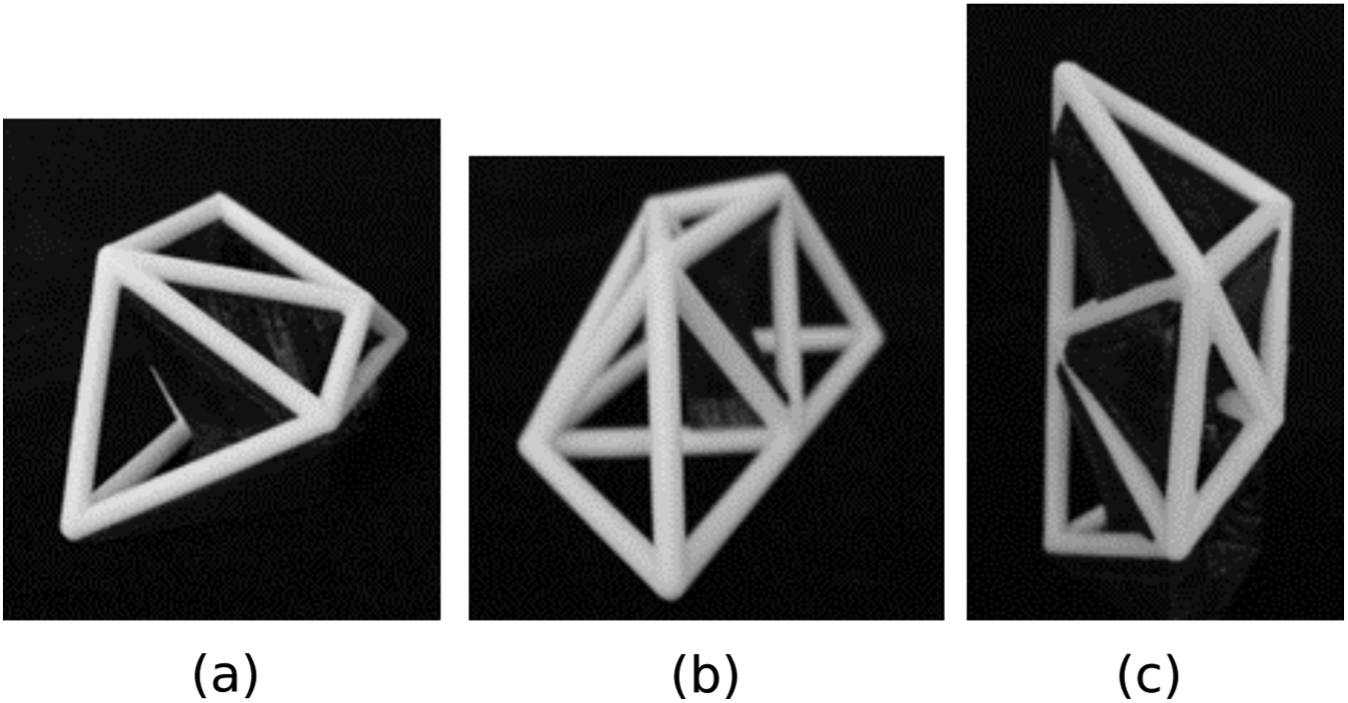
The 3D trusses printed using different deposition planes: (a) the optimal plane [0, 1, 0], (b) a non-optimal plane [0, 0, 1] and (c) a non-optimal plane [1, 0, 0].
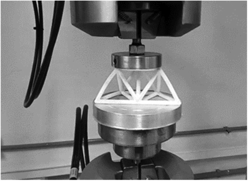
Compression test.
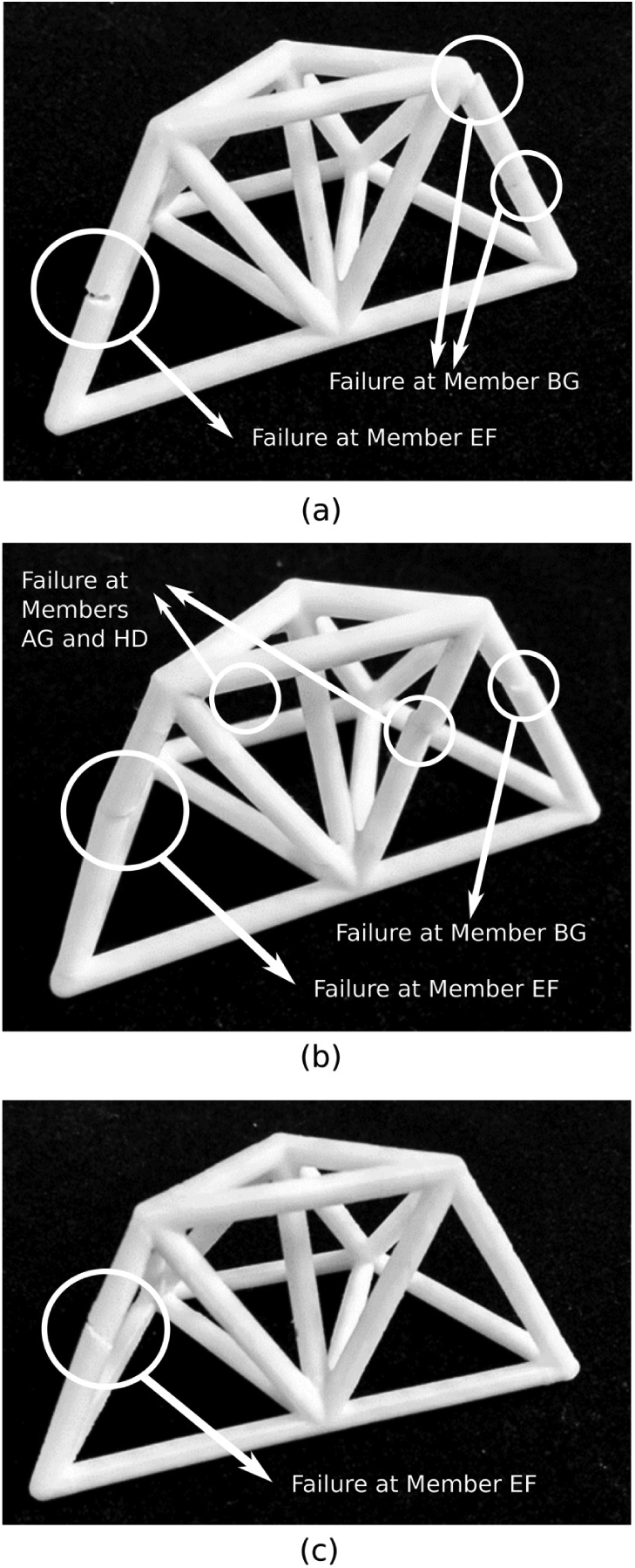
Member’s failures at the compression test for the 3D trusses printed using different deposition planes: (a) the optimal plane [0, 1, 0], (b) a non-optimal plane [0, 0, 1] and (c) a non-optimal plane [1, 0, 0].
The average load peak for each deposition plane of case 2.
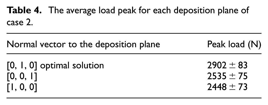
Finally, for case study 2, it is important to highlight that the option that requires the smallest amount of support material is the non-optimal [0, 0, 1] deposition plane, as illustrated in Figure 11. According to Table 4, the [0, 0, 1] is not the worst scenario. In this way, this also shows that the trade-off between the optimal deposition plane for minimizing the material support and for maximizing the tensile strength is not straightforward and might be case dependent.
Conclusion
Parts manufactured using FDM may present strong anisotropy. This characteristic imposes important limitations to the strength of the part, which is critical to its performance. In this work, an optimization problem is proposed for finding the best deposition plane of 3D truss-like structures manufactured using FDM. The optimization problem attempts to minimize the angles between the directions of the filaments and the tensile forces. The strategy is exploited for the selecting the optimal deposition planes (optimal build surface plane) of two 3D truss-like structures. The nature of the proposed optimization problem is case dependent. In this way, the algorithms for solving these problems should be selected according to this nature. Experimental campaigns were carried out for evaluating the parts using the optimal and non-optimal deposition planes. It can be concluded that a rational selection of the deposition plane can be beneficial for the mechanical strength of the device since higher yield tensile strength could be achieved by adopting the optimal deposition plane for 3D truss-like structures manufactured using FDM. The definition of an optimal deposition plane for more complex geometries would require a numerical assessment of the tensile forces and an extension of the proposed strategy. Moreover, the trade-off between the optimal deposition plane for minimizing the material support and for maximizing the tensile strength is not straightforward and might be case dependent. Finally, this work demonstrates the potential and advantages of exploiting optimization techniques in AM.
Footnotes
Acknowledgements
The authors are thankful for their research grants (CNPq and CAPES).
Declaration of conflicting interests
The author(s) declared no potential conflicts of interest with respect to the research, authorship and/or publication of this article.
Funding
The author(s) received no financial support for the research, authorship and/or publication of this article.