
Abstract
Fused filament fabrication (FFF) and Fused deposition modeling (FDM) are among the most common methods of additive manufacturing technology for a variety of industries. However, the extrusion-based process of these technologies has qualified the usable materials to thermoplastics with inherently limited mechanical properties. Augmenting the properties of these materials by blending them with other polymers or their reinforcement with various additives are among the solutions to overcome this issue. This study examines the result of the introduction of Polybutylene Terephthalate (PBT) to acrylonitrile butadiene styrene (ABS), as one of the most common thermoplastics used in FDM/FFF processes, and explores the effects of the incorporation of Multi-Walled Carbon Nanotubes (MWCNT) to ABS/PBT blend with different filler fractions (0.1, 0.3, and 0.5 wt.%) on the mechanical properties of the printed specimens. In order to assess the mechanical behavior of the printed parts, standard melt flow index (MFI), tensile, three-point flexural, and notched impact tests have been performed on the produced parts. The morphological analyses through Scanning Electron Microscopy (SEM) micrographs have been conducted to inspect the distribution of impregnated MWCNTs and the fracture behavior of the specimens. The most satisfactory improvement has been observed in printed parts of the ABS/PBT/CNT nanocomposites containing 0.3 wt.% of MWCNTs.
Keywords
Introduction
Although injection molding of thermoplastic polymers has been one of the preferred methods due to its rather good design flexibility and high-quality products, its costly initial tooling, especially for customized and complex parts and small batch sizes, is one of the main reasons that has turned attention to additive manufacturing technology. 1 Additive manufacturing (AM), commonly known as 3D printing, refers to a group of state-of-the-art manufacturing techniques and computer-controlled processes through which three-dimensional parts are created by the successive layers of materials.2,3 AM has not been circumscribed by process-dependent designs, high cost of mold and labor, or high waste of time and resources.2,4 The agile and flexible nature of this technology can be considered as a compelling enough reason for its increasing utilization in a variety of fields, such as building construction, space industry, food and agricultural implements, automobile industry, etc.5–9
Fused Deposition Modelling (FDM) and Fused filament fabrication (FFF) are among the most popular and accessible techniques of AM.10–12 In these methods, the CAD file of the object is converted to STL format. As depicted in Figure 1, a thermoplastic material gets fed through rollers and a heated extrusion nozzle. Then, thermoplastic is melted and extruded on the build bed or formerly deposited layer. According to the model, a computer controls both nozzle and table movements, and the final model gets fabricated through layers of material.4,11,13 Process schematic of extrusion-based additive manufacturing.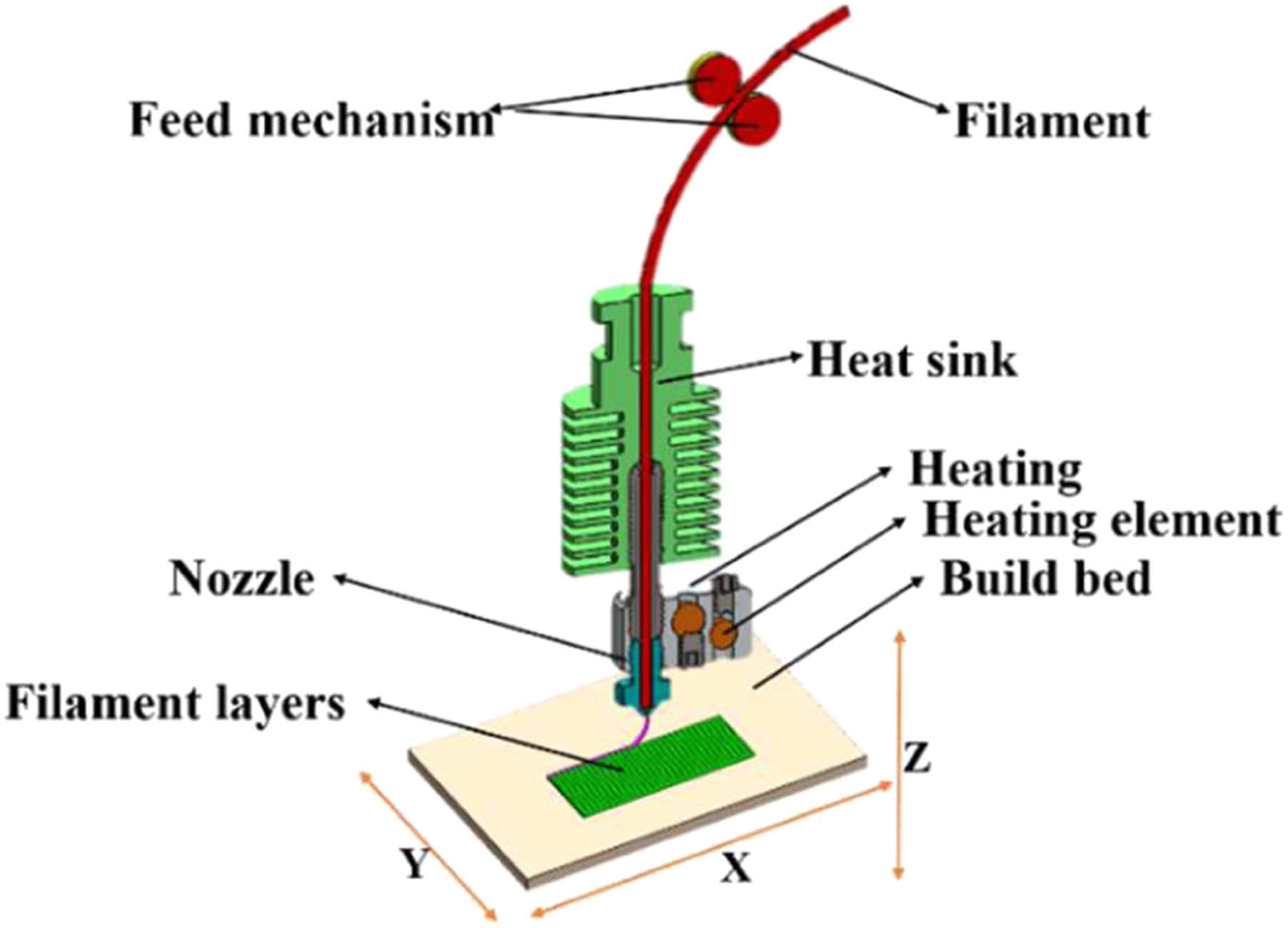
One of the limitations associated with the extrusion-based 3D printing technique is its limited range of printing materials. 14 These processes are best suited to thermoplastic polymers, which have good thermal and rheological properties and compatible, dissolvable support materials. This makes Polylactic Acid (PLA) and Acrylonitrile Butadiene Styrene (ABS) two of the most favorable materials for these technologies.1,2,15 Most of the time, these materials cannot meet the requisition of actual applications.16,17 These shortcomings restrain the broad applications of FDM/FFF technologies. Combining 3D printing and nanotechnology can be considered as an efficient solution to overcome these deficiencies and produce high-quality and multifunctional products with optimized properties.12,18 Therefore, during the past decades, there has been a significant focus on incorporating various nanoparticles, especially carbon-based nano-fillers and fibers, for developing composite and nanocomposite materials with appropriate properties, controllable functionality, and printability.
Zhong et al. 19 had used different contents of short-fiber fillers to overcome the deficiencies of ABS filaments used in the FDM process. They observed improvement of strength in short glass fiber reinforced ABS (GFABS) nanocomposites and a decline in their flexibility, which was later improved by the addition of small amounts of plasticizer and compatibilizer. Shofner et al. 20 reinforced ABS with nanofiber with a maximum inclusion of 10 wt.% to create a nanocomposite for the FDM process. In accordance with the Scanning Electron Microscopy (SEM) images, they witnessed a high quality evidenced with uniform dispersion and low porosity. Their results indicated 39 and 60% of enhancement in tensile strength and modulus, respectively. Ning et al. 21 had studied the FDM of thermoplastic (ABS) matrix carbon fiber reinforced plastic (CFRP) composites. They investigated the effect of carbon fiber content and length on the tensile and flexural properties of the specimens and determined the optimum value for each variable. Dul et al. 22 incorporated 4 wt.% of graphene nanoplatelets (xGnP) to ABS filaments through melt compounding and extrusion instead of using a solvent. They investigated the tensile properties of the specimens in three different build orientations and observed improvement in all of them. Reports regarding the advancement of thermal properties, stability, and creep compliance were also part of their study. Yamamoto et al. 12 suggested a low amount of graphene oxide (GO) inclusion to ABS through acetone evaporation process as an efficient and economical material for the FFF/FDM process. The conducted examinations on their newly developed materials demonstrated good advancement in failure strain, toughness, fracture strength while showing a decrease in stiffness. Ahmed et al. 17 looked into the tensile performance of the hybrid composites printed from ABS filament and carbon-fiber-reinforced polylactic acid (CF-PLA) filament. They also inspected the influence of printing speed, layer height, and clad ratio in printed specimens’ performance, observed different fracture types, and decided the optimum parameters to obtain desired properties. In an attempt to develop nanocomposite 3D printing filaments with better electrical properties and conductivity, Vidakis et al. 23 incorporated graphene nanoplatelets (GnP) at various concentrations and carbon nanotubes (CNTs) to ABS. Although they reported a seven-fold increase while incorporating 10 wt.% of CNT, they noticed an increase in dielectric constant even at a 10 wt.% concentration of GnP. They also studied the tensile and flexural strength of specimens and reported a downgrade in the case of adding GnP to ABS and an increase in the case of CNT inclusion. Later, Podsiadly et al. 24 examined the effect of incorporating carbon nanotube (CNT) fillers to ABS matrix on the enhancement of mechanical and electrical properties of 3D printed specimens, and determined the optimized content of CNTs to obtain the best result.
As indicated in the studies mentioned above, many attempts have been made to broaden the application of FFF/FDM processes by overcoming the deficiencies through the reinforcement of nanofillers and fibers in commonly used thermoplastic materials. The main objective of the present study is to develop new nanocomposites with 3D printing processibility through efficient and economical materials and methodologies to further expand the envelope of materials for the mentioned technologies. ABS was selected as the base thermoplastic material owning its availability and processibility. As a semi-crystalline thermoplastic with higher strength, lower fracture toughness, and sensitiveness to defects, PBT was incorporated into ABS to obtain a blend with partially improved mechanical properties. 25 Then, Multi-Walled Carbon Nanotubes (MWCNT) with outstanding mechanical and thermal properties were included in the ABS/PBT blend in varying contents (<1 wt.%) to investigate the further promotion of the mechanical properties and improvement of the declined fracture toughness as an attendant effect of adding PBT to ABS. Melt flow index (MFI), tensile, three-point bending, and notched impact tests were carried out to assess the mechanical behavior of the produced prints. SEM imaging and analyses were also conducted to study the specimens’ morphological and fracture behavior.
Experimental procedures
Materials
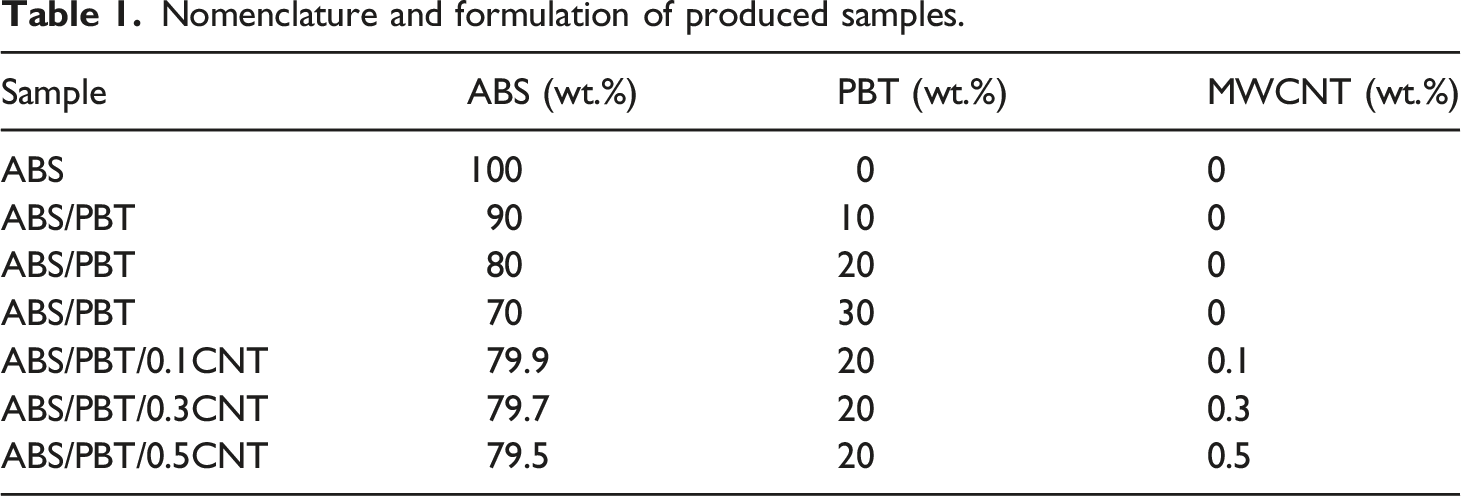
Acrylonitrile butadiene styrene (ABS (N50 grade)) with a purity of at least 97%, the specific gravity of 1.09 g/cm3, and melting temperature around 220°C was maintained by Ghaed Bassir Petrochemical Company, Iran. Polybutylene Terephthalate (Tecodur® PB70 NL) with a specific gravity of 1.04 g/cm3 and melting temperature of 270°C was purchased from Eurotec® Engineering Plastics Company, Turkey. Multi-walled Carbon Nanotubes (MWCNT) with an average outer diameter of 25 nm and an average length of 25 μm, US Research Nanomaterials, Inc., was incorporated as reinforcing inclusion.
Polymer blend and composite development
Nomenclature and formulation of produced samples.
Filament extruding and 3D printing
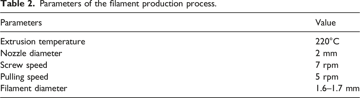
Fused deposition modeling/Fused filament fabrication is an additive manufacturing technology based on filaments. Thus, the intended materials (virgin ABS, ABS/PBT blend, and ABS/PBT/CNT nanocomposites) have been turned into feedstock filaments that are appropriate feed to the 3D printer. To make filaments, a filament production line, like a mini lab-scale filament extruder system, was contrived by the researchers of this paper at the University of Tabriz. As shown in Figure 2, the filament production system mainly consists of a mini single-screw extruder, an extrusion die to control the thickness of the plastic film, a cooling fan, and a filament puller. The intended material enters the mini extruder, softens with the increase of temperature, and gets extruded in the form of a continuous filament. Then, the extruded filament cools and solidifies in the justified diameter while being dragged by the puller. The suitable diameter of filaments for the 3D printer used in this study is 1.6–1.7 mm. To have better continuity while extruding filaments, parameters were optimized for fabricating the required filaments and are recorded in Table 2. Filament extruding line. Parameters of the filament production process.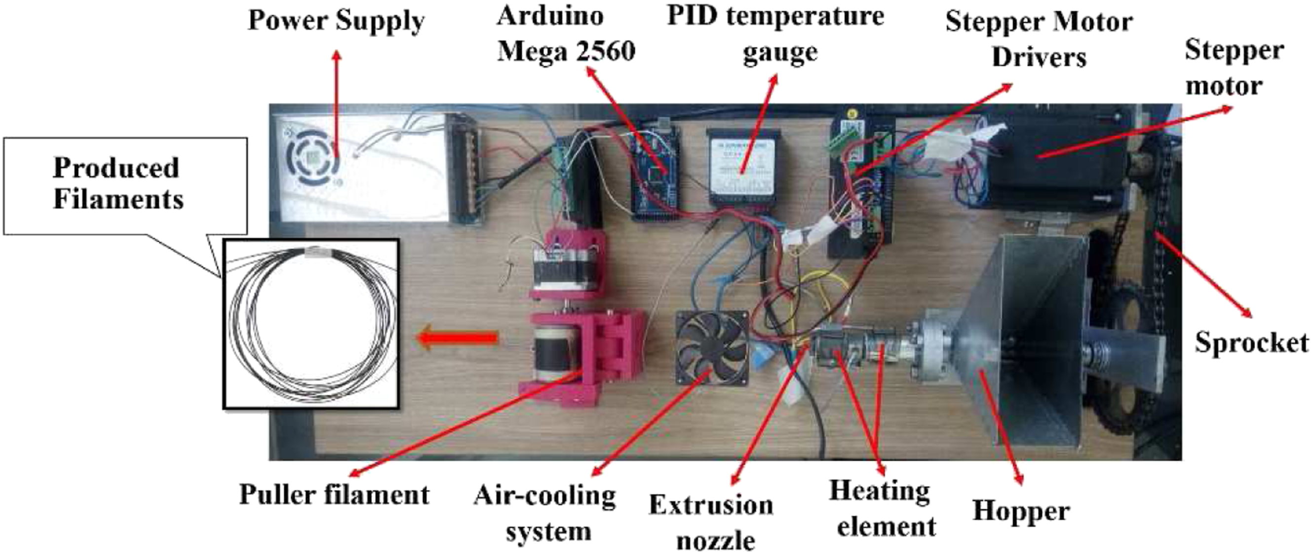
To print the specimens, a delta robot 3D printer, as depicted in Figure 3, was designed and fabricated by the researchers of this paper. In order to set up and control the constructed 3D printer, the open-source firmware of Marlin was used, and to generate the toolpath, the open-source software of slic3r was employed. Delta robot 3D printer (a) schematic of the designed printer (b) constructed printer.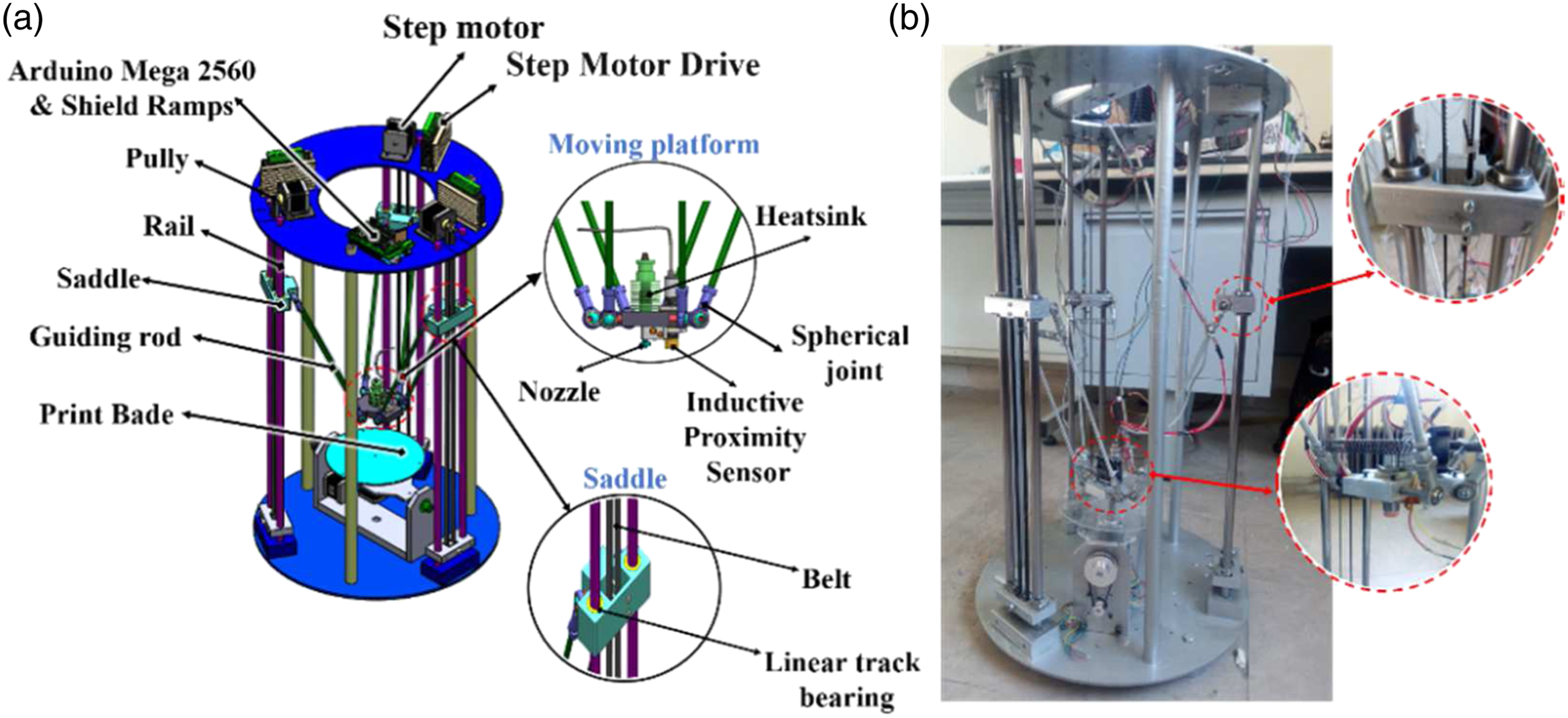
Testing printed specimens
Melt flow index (MFI) value is of cardinal importance in controlling printability and final quality of prints. 27 Therefore, it is among the tests conducted on materials of this study. The MFI test was performed by Ray-Ran MFR 200 Melt Flow Index (MFI) apparatus and according to ASTM-D1238. In this test, the material flows through a formerly heated barrel of the instrument with a load of 3.8 kg at the specified temperature of 240°C. Then, a 10-min extrudate is gathered and weighed to calculate its MFI value in g/10°min.
Morphological analysis of the prints can also be enlightening since it gives a lot of information about the dispersal of impregnated carbon nanotubes and, more importantly, the fusion quality of ABS/PBT blend and ABS/PBT/CNT nanocomposites. The information from these studies can be pretty valuable while interpreting the fracture behavior of the polymer blend and nanocomposites. SEM micrographs were exploited for this objective.
Moreover, tensile, three-point flexural, and notched impact tests were carried out to characterize produced samples. Tensile tests were conducted to analyze the mechanical properties of samples, including their tensile strength and the elongation-at-the-break. The tests were in accordance with the ASTM-D638 standard at a cross-head speed of 5 mm/min by a ZwickRoell testing machine.
The three-point flexural test was performed using the GOTECH universal testing machine by placing the specimen on two rollers functioning as supports and exerting a concentrated force using the third roller at the specimen’s center. The applied force induces tension in the bottom center section of the part, and the increasing amount of it will lead to breakage. The maximum recorded force equals the flexural strength of the part. The parameters of this test were selected based on the ASTM-D790 standard, with speed being adjusted to 5 mm/min and supports being set at 50 mm from each other.
The notched impact test (Charpy V-notch test) has been run to determine impact strength. This test assays the amount of energy absorbed by the specimen before fracture and materials’ resistance to crack initiation and propagation. 28 The test was executed using a ZwickRoell testing machine and according to the ASTM-D256 standard using an impact capacity of 5.5 J and impact velocity of 3.5 m/s.
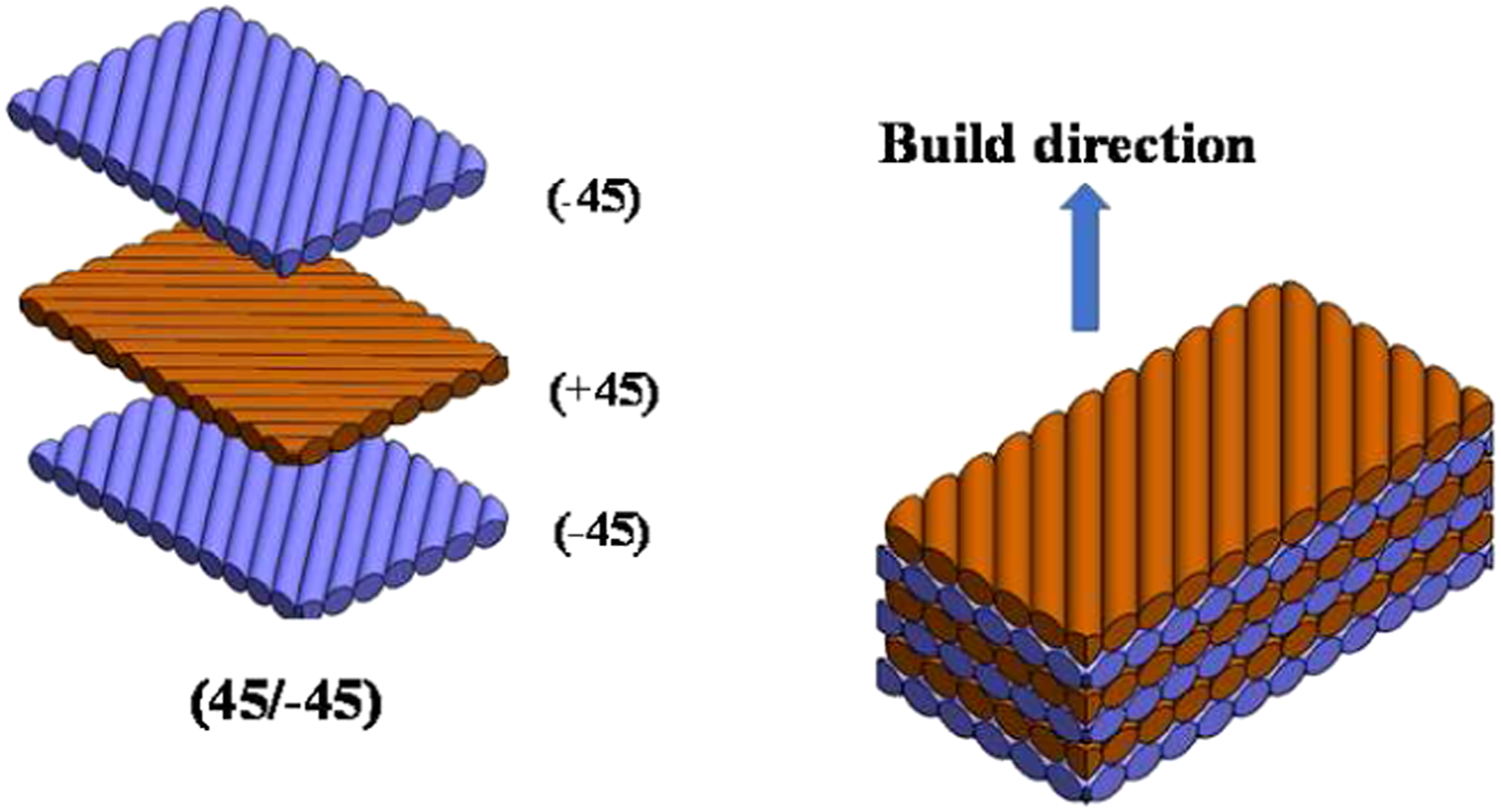
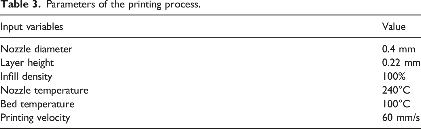
Three specimens of each sample for each test were printed and tested, and the average results were recorded. Specimens used in each of the tests and their corresponding standard dimensions are shown in Figure 4. As it is illustrated in Figure 5, specimens were printed with an infill percentage of 100% and raster angle alternating between ±45°.29,30 The 3D printing process settings and parameters are presented in Table 3. Standard samples for mechanical test (a) tensile sample (b) flexural sample (c) impact sample. Raster orientation direction ±45°. Parameters of the printing process.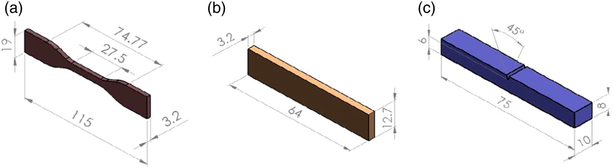
Results and discussion
Melt Flow Index test
MFI can play a paramount role in the quality of the printed parts; it directly affects the bonding quality and, thereby, parts’ mechanical performance. Better rheological behavior of materials in extrusion-based 3D printing expedites the distribution of material during the printing process, reduces void content, and results in a print with stronger mechanical characteristics.
27
According to what is seen in Figure 6, the addition of PBT to ABS with different fractions of 10, 20, and 30% improves MFI by 22, 58, and 71%, respectively. The addition of 20% wt. of PBT is more effective in enhancing the MFI since, in this case, the ratio of the melt flow index’s increase to the weight fraction of PBT used is more than the other two mixtures. Thus, polymer blend ABS/PBT (80/20) was selected as the matrix, and the effect of using carbon nanotubes in this blend was studied. Comparing melt flow index (MFI) of ABS/PBT blend and ABS/PBT//CNT nanocomposites.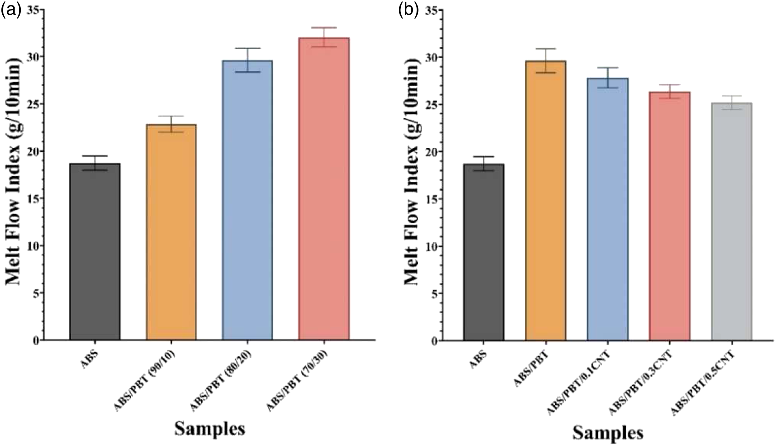
Figure 6 Compares values of MFI for ABS, ABS/PBT (80/20) blend, and ABS/PBT/CNT nanocomposites with different filler fractions of MWCNTs (0.1, 0.3, 0.5 wt.%) in ABS/PBT blend matrix. PBT’s higher melt fluidity compared to ABS is the reason for the evident increase in the blend’s melt flow. However, adding 0.1, 0.3, and 0.5 wt.% of MWCNTs to the blend decreases the blend’s MFI by 6, 11, 15%, respectively. This decline can be attributed to the reduced chain mobility of the polymer blend as the result of MWCNTs’ presence in its structure. Moreover, MWCNTs can further reduce fluidity by matrix-filler interaction and enhancing the ABS/PBT miscibility. Of course, it is noteworthy that although the incorporation of MWCNTs to the blend lowers the blend’s fluidity, nanocomposites’ MFI is still higher than that of virgin ABS.
Morphological characteristics
Scanning electron microscopy of fractured samples at 10,000x magnification has been employed to examine specimens’ structure and carbon nanotubes distribution.
As it is evident in Figure 7, adding PBT to ABS has engendered a conspicuous modification in the sample’s cross-sectional structure. Although this polymer blend is immiscible, the higher melt flow of PBT has led to its good dissipation in the ABS matrix.25,31 It is evident inFigure 7(b) that the distribution of PBT in the ABS matrix is quite uniform; it is characteristic of a compatible polymer blend and sufficiently strong interactions between the component polymers. Scanning electron microscopy micrographs of fractured surfaces of the ABS polymer and ABS/PBT: (a) bare ABS; (b) ABS/PBT (80/20).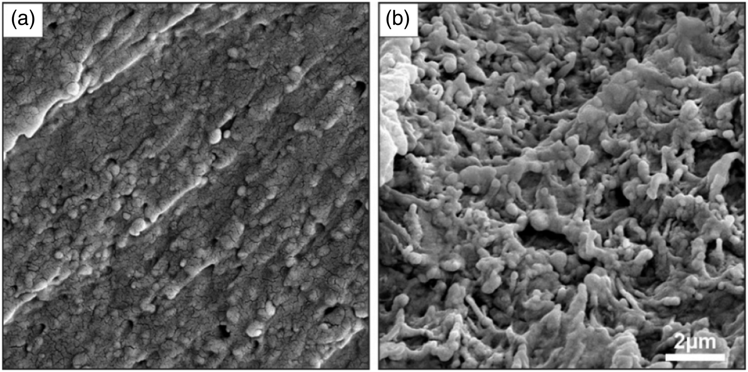
Uniform or non-uniform distribution of carbon nanotubes can also severely affect the mechanical behaviors of the nanocomposites. This makes morphological study a crucial tool in interpreting the nanocomposites’ mechanical behaviors. Figure 8 shows SEM images of nanocomposites containing 0.1, 0.3, and 0.5 wt.% of MWCNT, which are pointed with the yellow arrows. Adding carbon nanotubes in the mentioned fractions has created a relatively rough, layered surface. Scanning electron microscopy micrographs of fracture surfaces: (a) ABS/PBT/0.1CNT; (b) ABS/PBT/0.3CNT; (c) ABS/PBT/0.5CNT.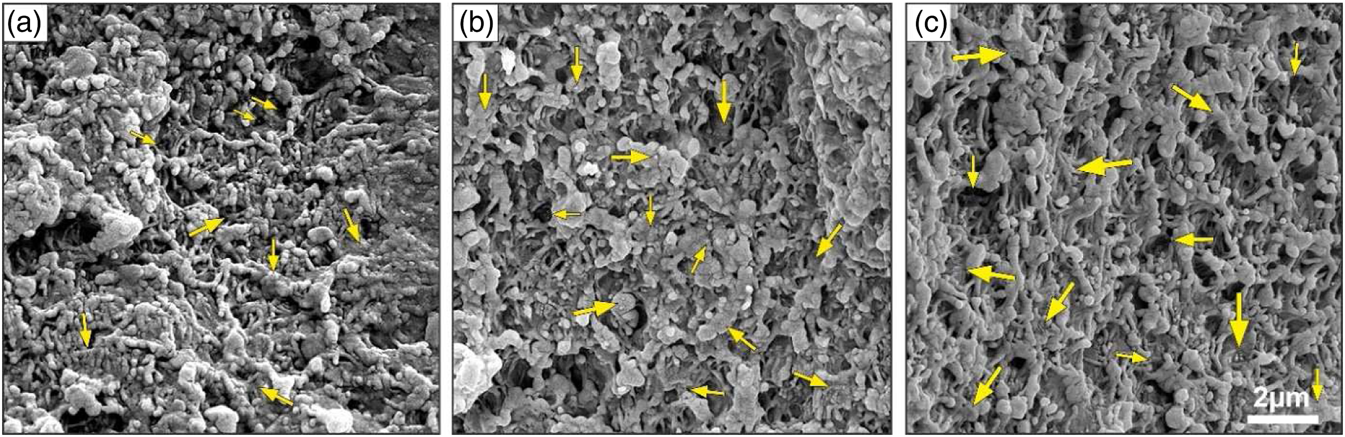
This roughness can be attributed to carbon nanotubes scattered rather uniformly in both phases. These carbon nanotubes hamper the crack growth and the separation of layers by interconnecting the structures and bridging the cracks in the base matrix. The bridging mechanism can serve as an efficient means for improving the strength of composite and facilitating the load transfer.28,32,33 Also, the incorporation of carbon nanotubes can be conducive to restoring the ductile behavior of the samples by leading to the growth of the neck in filaments and their interfacial bonding. This behavior adequately justifies the samples’ crude and layered cross-section.
Nonetheless, it should be taken into account that increasing the filler fraction of carbon nanotubes may lead to their agglomeration and decrease in mechanical properties. Although carbon nanotubes are distributed uniformly in all three cases of Figure 8, small aggregations of nanotubes have started to form in some parts of the sample with a filler fraction of 0.5 wt.%.
All of the mentioned factors can affect samples’ mechanical properties, further elucidated in the following sections.
Tensile test
In this study, adding the PBT phase to the ABS base has led to a 9% increase in samples' tensile strength and a decrease of 10.8% in the samples’ failure strain. To further improve the tensile strength of the ABS/PBT (80/20) blend and retain some of ABS’s mechanical properties, such as higher failure strain and ductility, carbon nanotubes with different filler fractions were added to the blend. According to Figure 9, adding carbon nanotubes with filler fractions of 0.1, 0.3, and 0.5 wt.% to the ABS/PBT matrix has improved the blend’s tensile strength by 2.2, 12, and 13.9% and has increased its failure strain by 0.47, 9.2, 9.4%. Remarkable tensile strength and failure strain improvements can be discerned in the specimens with MWCNT fractions of 0.3 wt.%. Comparison of (a) tensile strength and (b) failure strain percentage for different samples.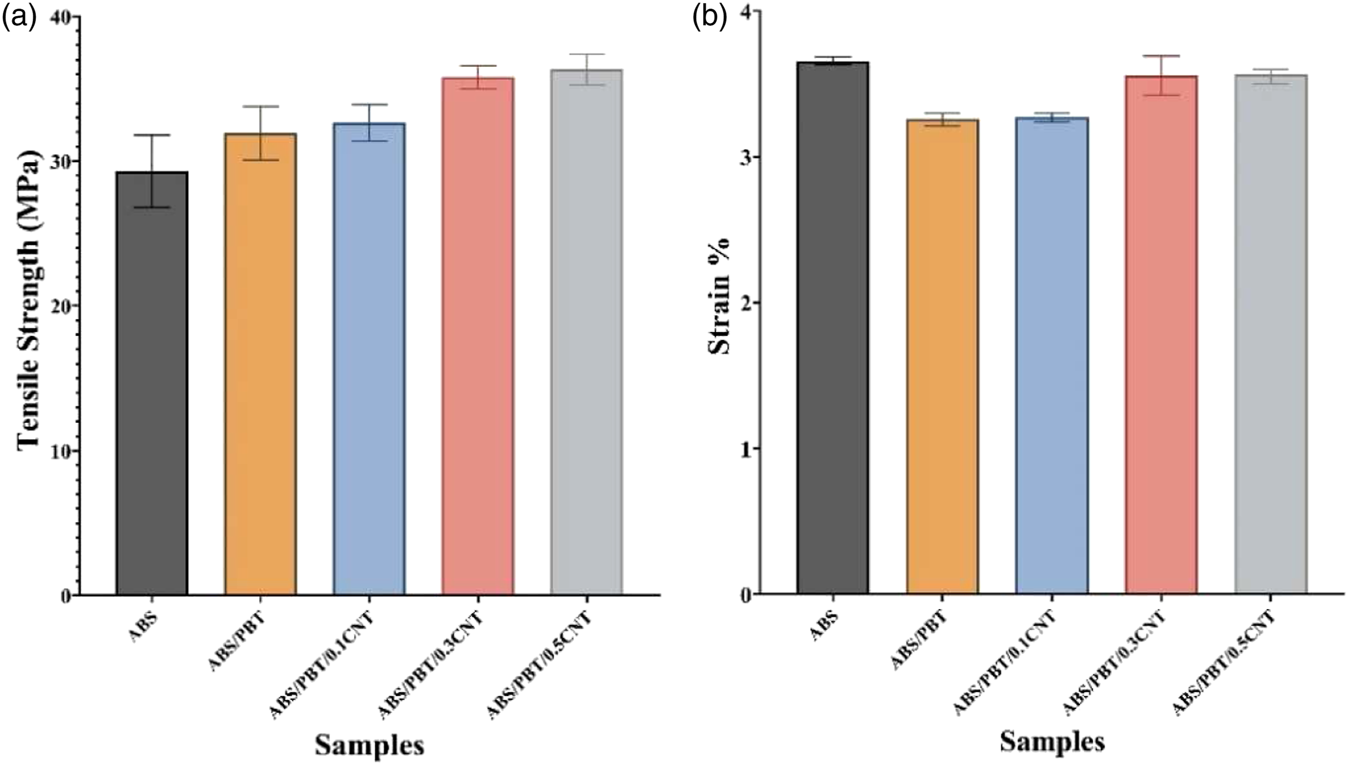
Mechanical properties of the samples are influenced by the addition of PBT with higher tensile strength. Also, PBT’s higher MFI increases the mobility of the polymer outflowing from the nozzle. Thereby, the addition of PBT affects the adhesion of layers and rasters to each other and plays a significant part in improving inter-filament bonding. However, the brittle nature of the PBT has lowered the failure strain and ductility of the samples and made them brittle. Regarding the impregnation of MWCNTs, two factors play critical roles in improving the mechanical properties of samples: (1). Uniform distribution of MWCNTs and lack of agglomeration contributing to desirable results 34,35; (2). Proper adhesion between nanotubes and the base matrix, which leads to stronger mechanical qualities. Both of these factors can be observed in SEM images of Figure 8. The distribution of the carbon nanotubes is reasonably uniform, and their seemingly bigger size indicates their proper coverage by matrix and thus satisfactory phase adhesion and interference. 33
About the positive effect of MWCNTs on the blend, it should be said that carbon nanotubes' inherent ductility can play a role in increasing the failure strain of the nanocomposite samples. Also, by their uniform dispersal and good adhesion to the matrix, they can form an interconnecting structure between the phases, buffer the stress, and effectively transfer the stress to the immiscible phases of the ABS/PBT blend. Thus, the adequate inclusion of the carbon nanotubes can improve the tensile strength of the samples and filaments’ bonds and partially fix the deteriorated failure strain percentage due to the introduction of brittle PBT.
The stress-strain graph of the samples extracted from their tensile test is apparent in Figure 10. As it is evident after adding PBT, samples show a brittle behavior; however, in the case of ABS/PBT/0.3CNT composite, the ductile behavior is retained to some degree. Strain-Stress curve of produced samples.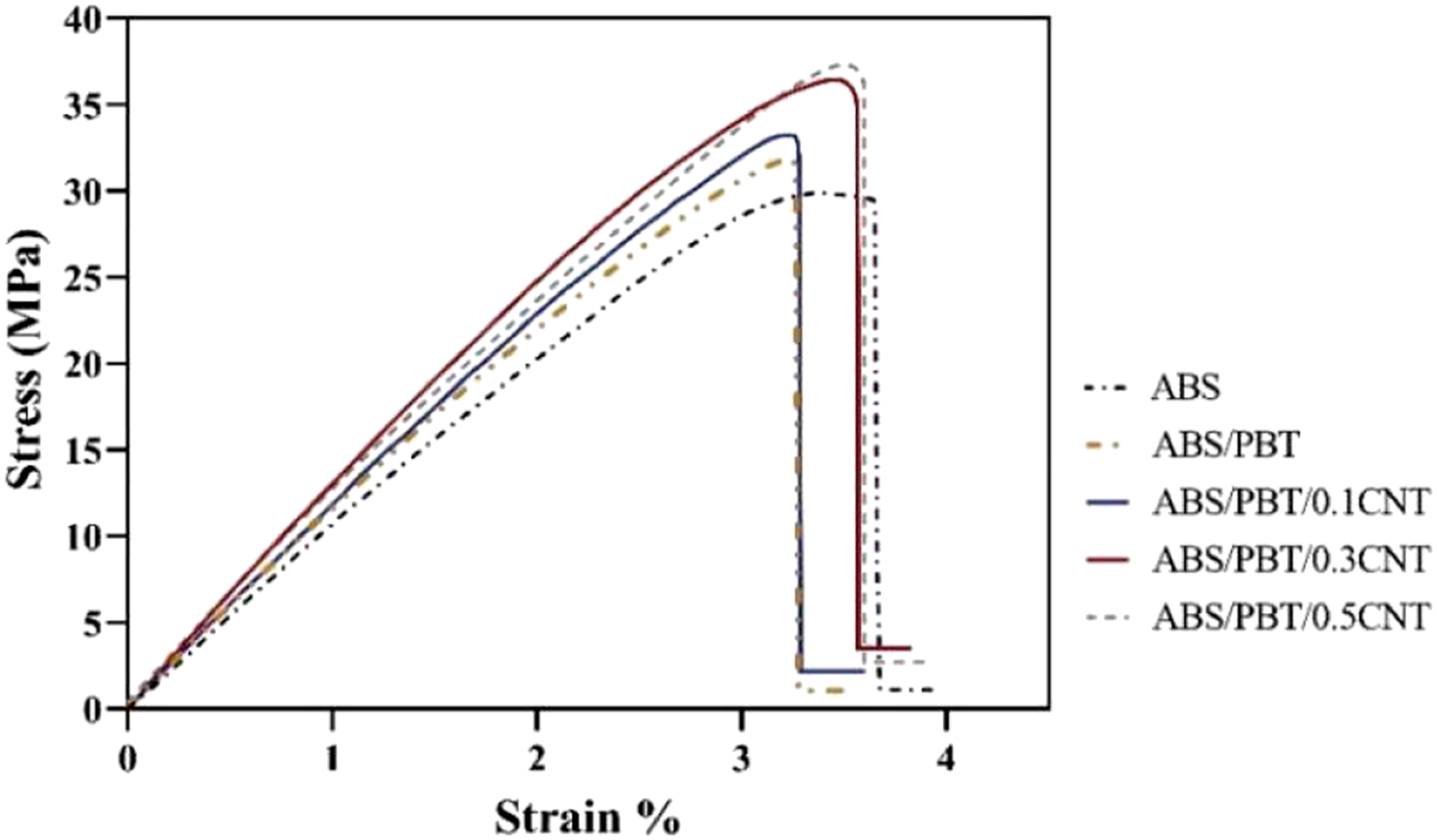
For further physical analysis of the ruptured samples and inspecting their fracture behavior, the macroscopic fractured surfaces of the tested samples are provided in Figure 11. In the case of virgin ABS, the fractured surface is jagged and layered, and near the broken section, some crazes (white crack lines) formed and developed prior to the breakage. All of these are indictor of a relatively ductile behavior. PBT sample’s fracture surface is not layered, and there are no crazes discerned around. This behavior can be attributed to PBT’s brittle fracture behavior and compact layers. In nanocomposite samples containing MWCNT, mostly, a saw-tooth pattern fracture line is evident. The reason for the formation of these lines is the separation of filaments at a ±45° angle with respect to the tensile load. These paths are controlled by infirm filament bonding as the result of samples’ shrinkage during cooling and air voids between filaments that reduce the load-bearing cross-sectional area, providing an easy fracture path.
29
Also, the tiny crazes around the fractured section of the sample containing 0.3 wt.% MWCNT is emblematic of moderate restoration of ductile behavior. Ruptured tensile test specimens of (a) ABS, (b) ABS/PBT, (c) ABS/PBT/0.1CNT, (d) ABS/PBT/0.3CNT, (e) ABS/PBT/0.5CNT.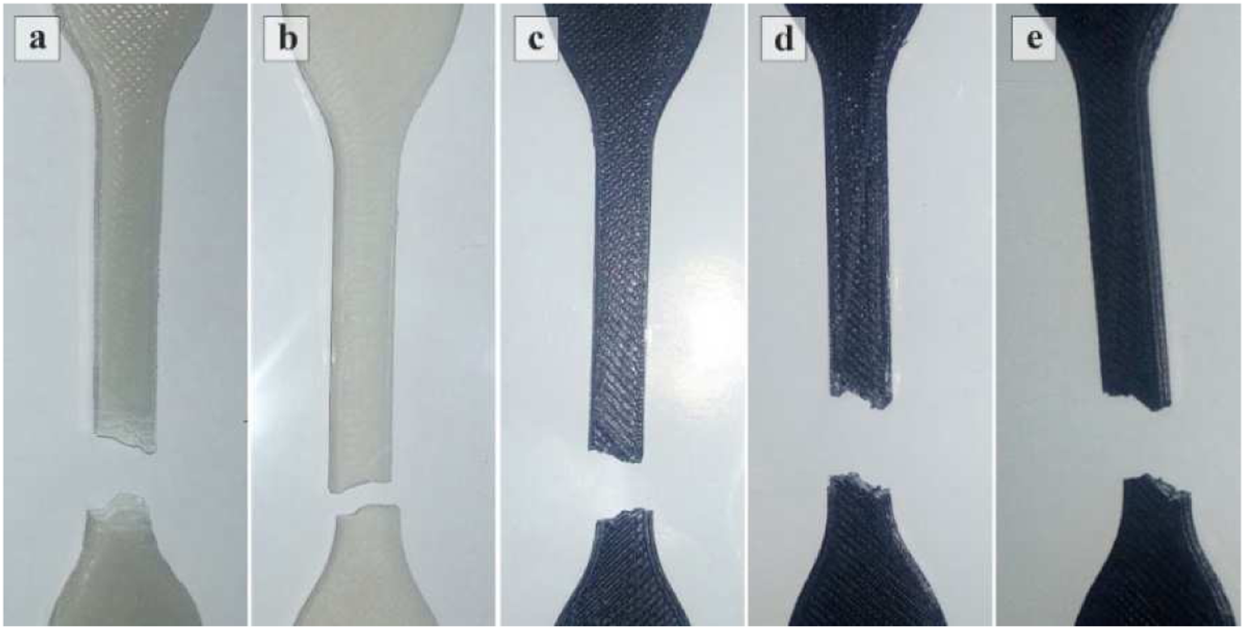
In line with the standard theory of composite materials, 36 there has been anticipation of witnessing improvement in tensile strength of nanocomposites with the addition of nano-fillers. Although the results are not at odds with this standard, there is not a distinct improvement in the produced parts with 0.5 wt.% of CNTs compared to their 0.3 wt.% counterparts. Considering the fact that parts are printed, and the chosen raster angel is set at ±45°, tensile strength is affected by the bonding of filaments in addition to their strength. Nanocomposites’ decreased fluidity, which can influence filaments’ bonding, may be the culprit for this observation.
Moreover, in some studies,18–21,23 the addition of nano-fillers, such as glass/carbon fibers, carbon nanotubes, and metal particles in FFF/FDMed parts, has been accompanied by a reduction in their ductility and failure strain. These reductions can be attributed to the increased porosity in filaments or relatively weak interfacial bonding between fillers and thermoplastic matrices. However, the inclusion of less 1 wt.% of CNTs not only has not led to defects, such as porosity but interconnected the phased of ABS/PBT and resulted in the betterment of failure strain to an extent.
Three-point flexural test
The flexural properties of the samples denote their tendency to bend. Since bending loads can lead to the rupture of fibers and the delamination of layers, studying the flexural behavior of the samples will be a good evaluation of the strength of produced materials and bonding quality between consecutive layers. Delamination or micro-cracks between the samples’ layers happens where there is a deficiency of bonding between layers. This phenomenon can occur due to the fiber shrinkage, non-uniform distribution of melting polymer.
During the three-point flexural test, the layers below the mid-layer are subject to tension, and the layers above the mid-layer are under compression. In other words, only the fibers at the bottom and top layers of the samples are under the greatest amount of stress. In other words, unlike the tensile test during which all the layers were subjected to the same amount of tension, fibers are not under the same load in the flexural test. This phenomenon is the main reason for samples’ greater flexural strength than their tensile strength .37,38
During the three-point flexural test, cracks between the layers stretch through the lines toward the center (where the load is being applied); then, they meet the vertical cracks formed in the bottom layers, which are under tension, and lead to the failure of the samples.
The Flexural strength and modulus obtained through the three-point test are presented in Figure 12. According to what is seen, the flexural strength and flexural modulus of the ABS/PBT (80/20) blend has increased by 15.6% and 20.5%, respectively. This growth pertains to the higher flexural strength and modulus of PBT. This progress also can be attributed to PBT’s high MFI, which can increase the interlayer adhesion of the samples. Comparison of (a) flexural strength and (b) flexural modulus percentage for different samples.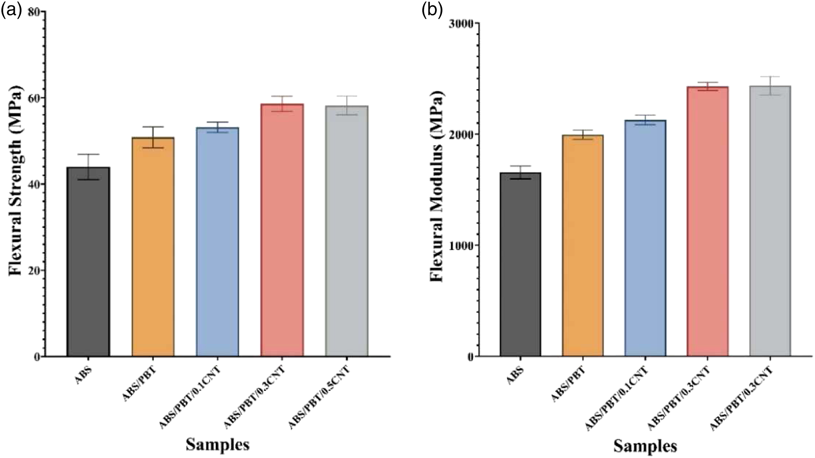
Carbon nanotubes with high flexural strength and modulus can also enhance flexural strength and modulus, especially if they have the proper distribution and adhesion to the matrix. According to Figure 12, it is observed that by adding carbon nanotubes with filler fractions of 0.1, 0.3, and 0.5 wt.%, flexural strength further increases by 4.6, 15.2, and 14.4%, and flexural modulus further improves by 6.6, 21.8, and 22.1%, respectively. A considerable improvement is noticeable in flexural strength and modulus in samples containing 0.3 wt.% of carbon nanotubes.
The reason for marginal improvement in flexural modulus and a slight decline in flexural strength regarding the case of 0.5 wt.% can be attributed to the reduction of fluidity which leads to weak bonds between filaments and layers and appearing agglomerations of MWCNT nano-fillers, which hobbles the proper fusion of layers. However, even in the case of flexural properties, there cannot be noticeable reductions due to the increase of nanofillers as reported in the studies, only including larger fractions of these fillers. 21
Figure 13 shows the broken specimens after the three-point flexural test. It is shown that the breakdown has been started on the bottom side of the specimens under the tensile load. However, the top surface layers that were under compression have remained unbroken. Failed three-point flexural test specimens of (a) ABS, (b) ABS/PBT, (c) ABS/PBT/0.1CNT, (d) ABS/PBT/0.3CNT, (e) ABS/PBT/0.5CNT.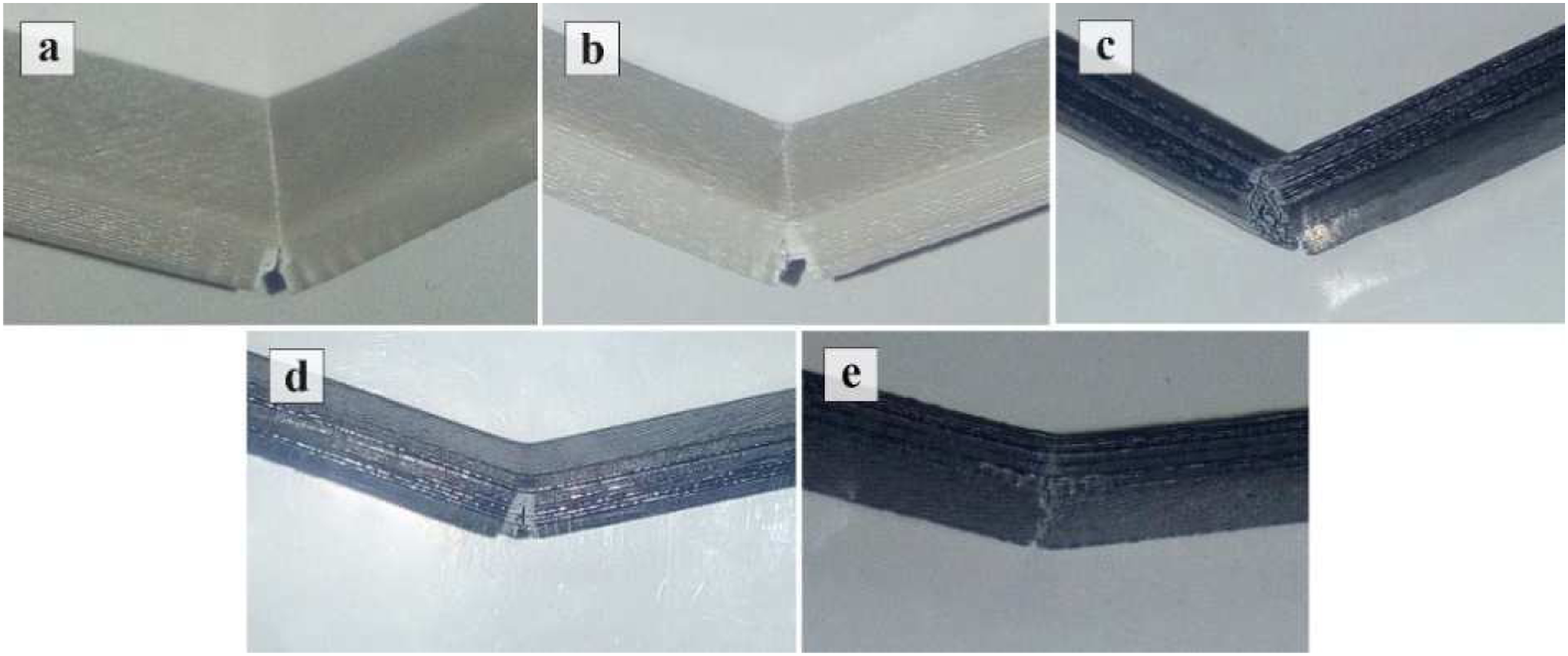
Notched impact test
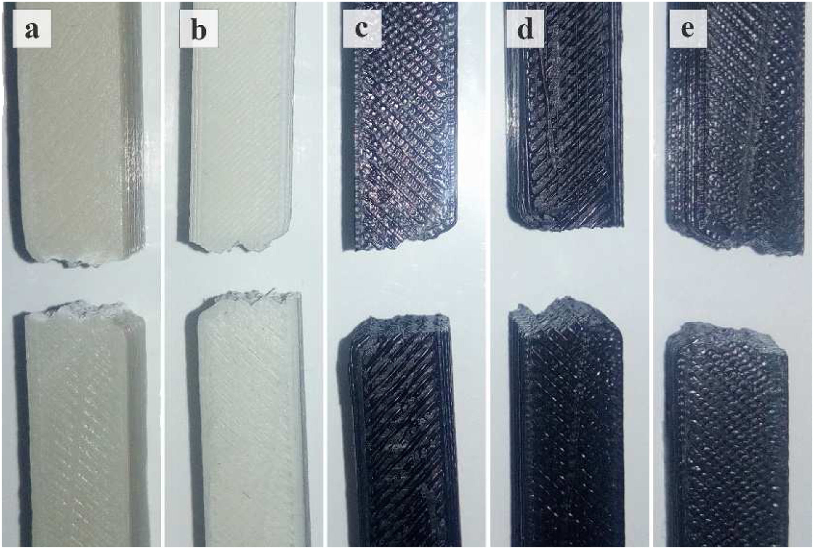
In order to assess the impact strength of the samples, a Charpy impact test was carried out. According to what is seen in Figure 14, by adding PBT to the ABS base, impact strength decreased by 38.4%. This decline is directly related to the PBT’s intrinsic low impact strength due to its high sensitivity to notched defects and pores. As mentioned before, the ABS/PBT blend is immiscible; the introduction of PBT to the ABS disrupts the continuity of the ABS phase, impedes energy absorption, and conclusively, leads to a deterioration in impact strength. The disrupted network for transferring energy also gives rise to erratic crack propagation and a relatively jagged fracture surface that can be observed in Figure 1525,39. Comparison of impact strength for different samples. Fractured notched impact test specimens of (a) ABS, (b) ABS/PBT, (c) ABS/PBT/0.1CNT, (d) ABS/PBT/0.3CNT, (e) ABS/PBT/0.5CNT.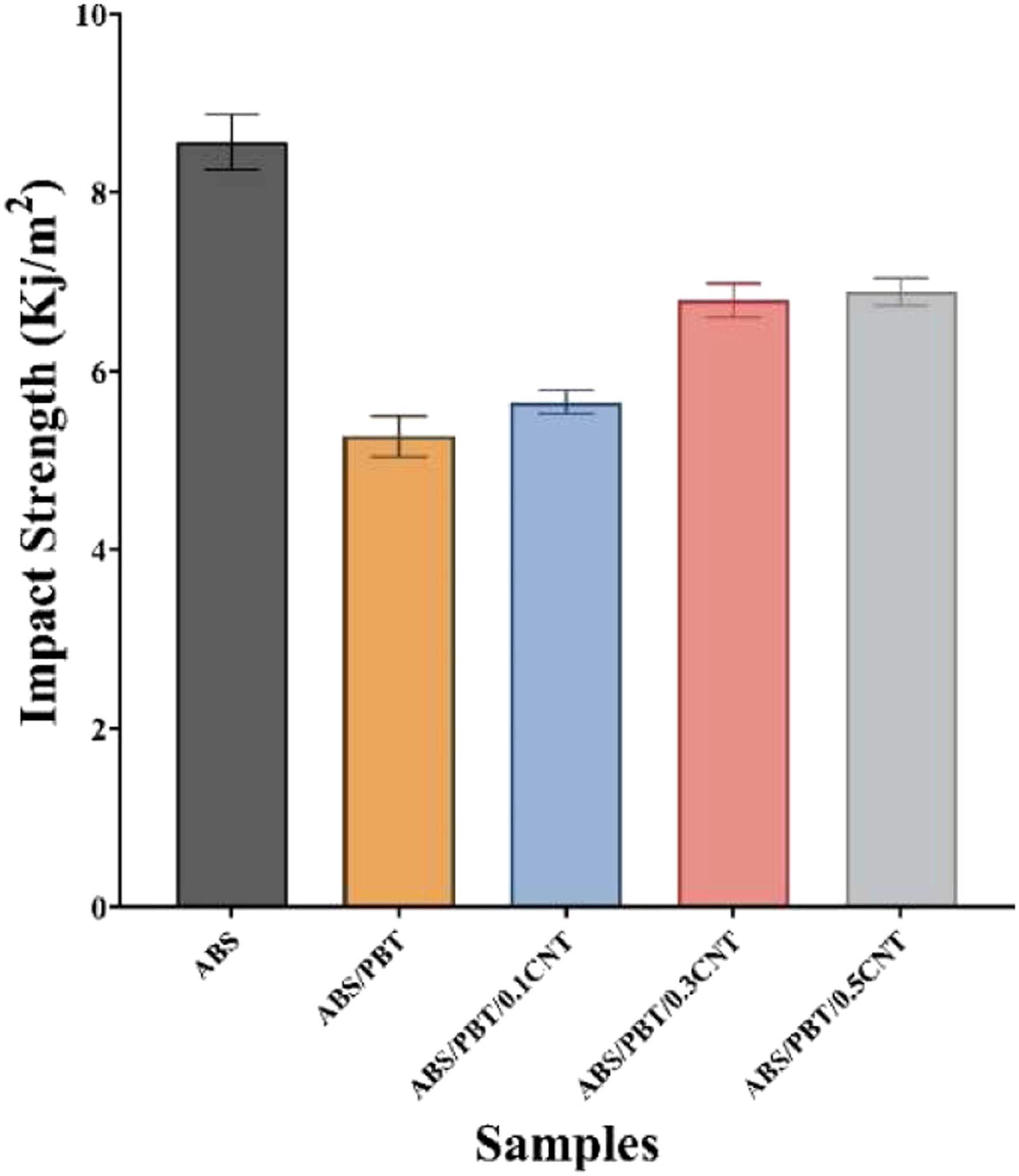
The decrease in impact strength was compensated to some extent by the impregnation of MWCNTs to the blend. Adding MWCNTs with fractions of 0.1, 0.3, 0.5 wt.% has improved impact strength by 7.2, 28.8, 30.6%, respectively. Samples with MWCNT fractions of 0.3 and 0.5 wt.% exhibit a good advancement. The addition of MWCNTs improves the impact energy by itself due to their high toughness and benefits the blends’ toughness in other ways. More precisely, the adequate incorporation of MWCNTs to the blend can bridge the phases and help the propagation and dissipation of energy through the ABS. 40
Figure 15 shows the examined samples and broken specimens after the notched impact test. The hinged and zigzag patterns of the samples’ fractured surfaces result from the raster angle of ±45°. This angle is assumed to stunt the growth of the crack and increase the impact strength of the specimens due to the mechanism named “crack deflection”. 1
Moreover, Figure 16 represents the SEM pictures of the fractured surface of impact test specimens for better inspection of the layer-bonding and the fracture behavior of the samples. As it is obvious in the SEM images, the existence of voids is a common characteristic in the 3D printed parts. However, due to the distinct qualities of the produced materials, different levels of bonding and filling can be achieved. Patterns resembling localized plastic deformations and small neck growth in filaments and between them are palpable on the image related to the ABS specimen (Figure 16(a)). This moderate deformation can be attributed not only to ABS’s intrinsic features but also to the process through which the sample has been produced. Samples’ stress concentrator has been shaped through the printing process, and it already contained some voids and defects inherent to the printing process. Therefore, the crack propagation is also affected by rasters of the stress concentrator.
41
In the case of the ABS/PBT blend (Figure 16(b)), erratic crack propagation and lines are detected due to the disrupted network of ABS-base. Almost the same narrative applies to the ABS/PBT/0.1CNT composite (Figure 16(c)) since the amount of MWCNT included as reinforcement is not sufficient to efficiently improve the interference between the two phases (ABS and PBT). Although little neck growth can be recognized in some filaments of the composites containing MWCNT fractions of 0.3 and 0.5 wt.% (Figure 16(d) and (e)), the abrupt little ridges and striations in the images are symptomatic of a not a very ductile fracture behavior. SEM image of fractured impact test specimens of (a) ABS, (b) ABS/PBT, (c) ABS/PBT/0.1CNT, (d) ABS/PBT/0.3CNT, (e) ABS/PBT/0.5CNT.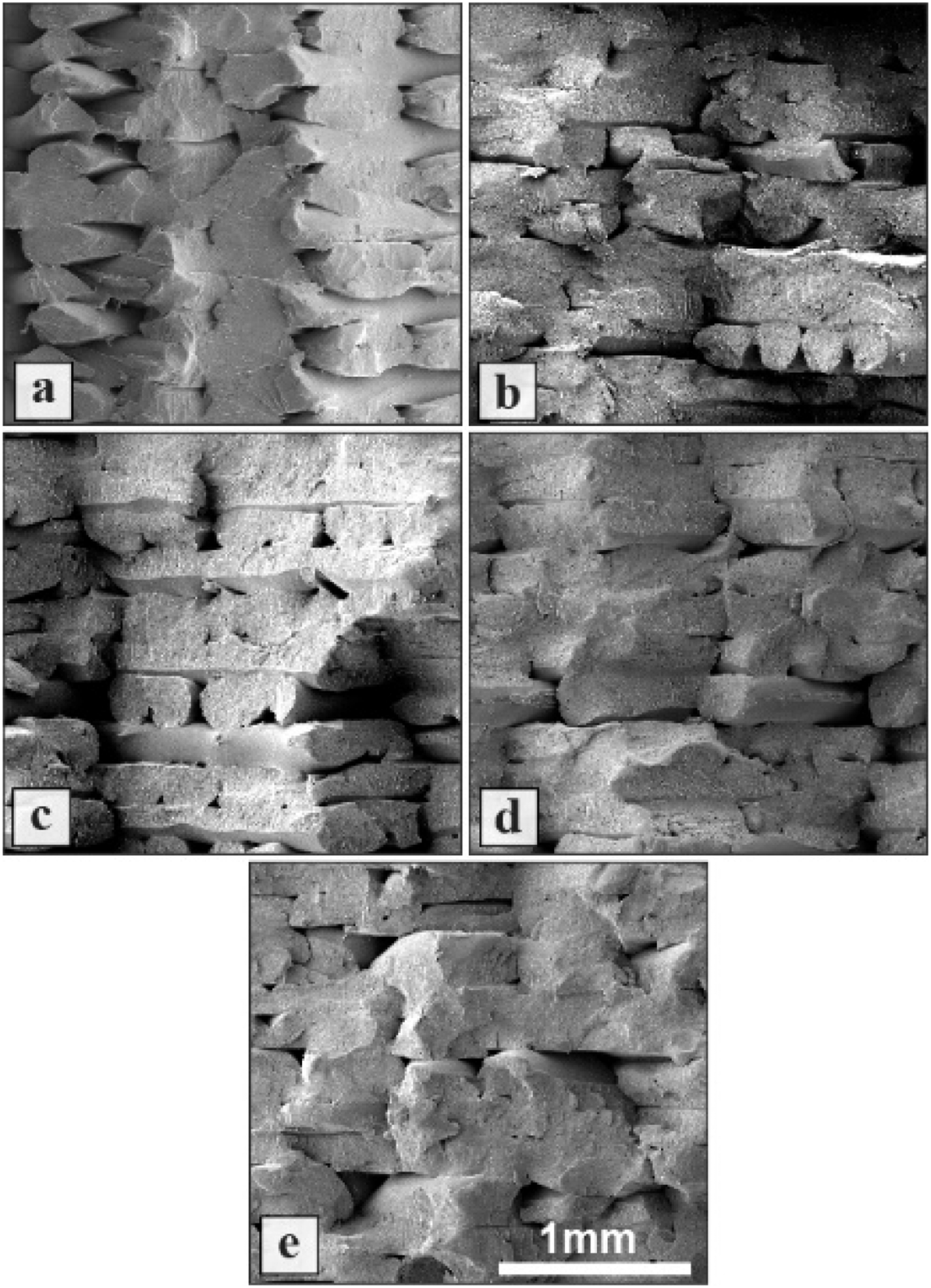
Conclusion
In this study, the effect of adding PBT polymer to ABS and carbon nanotubes to ABS/PBT blend on mechanical properties of produced samples was investigated. ABS/PBT blend and ABS/PBT/CNT nanocomposites with various filler fractions (0.1, 0.3, and 0.5 wt.%) were prepared by melt mixing, and a filament was prepared using a devised lab-scale filament extruder system from the resulted polymer blend and composites. Then, through melt flow index (MFI), tensile, three-point flexural, and notched impact tests, mechanical characteristics of 3D printed samples were explored. Morphological studies were conducted on the fractured surfaces of the samples to investigate qualities, such as distribution of nanofiller, porosity, and ductile behavior of specimens. • The Addition of PBT with different fractions of 10, 20, 30 wt.% to ABS base improved the melt flow of the blend by 22%, 58%, and 71%. The blend with 20% of PBT has been chosen as the base material since the it has shown the best improvement to fraction ratio. The incorporation of carbon nanotubes to ABS/PBT (80/20) with filler fractions of 0.1, 0.3, and 0.5 wt.% has decreased the blend’s MFI by 6, 11, and 15%, respectively. Nevertheless, the melt flow index remained higher than that of virgin ABS. • Incorporating PBT to the ABS base has increased its tensile strength by 9% and decreased its failure strain down to 10.8%. Tensile strength has further increased with the inclusion of carbon nanotubes with filler fractions of 0.1, 0.3, and 0.5 wt.% by 2.2, 12, 13.9%, respectively. Also, failure strain has offset by 0.47, 9.2, and 9.4% in comparison to the ABS/PBT blend. • The addition of PBT with higher flexural strength and modulus has increased flexural strength and modulus by 15.6% and 20.5%, respectively. Moreover, the inclusion of carbon nanotubes with great inherent flexural strength and modulus and with fractions of 0.1, 0.3, and 0.5 wt.% further boosts the flexural strength of samples by 4.6, 15.2, 14.4% and the flexural modulus by 6.6, 21.8, 22.1%, respectively. • By the inclusion of PBT to ABS, impact strength has been reduced by 38.4%. However, this reduction can be partially compensated by the incorporation of carbon nanotubes. Inclusion of carbon nanotubes with fractions of 0.1, 0.3, and 0.5 wt.% increases impact strength of ABS/PBT blend by 7.2%, 28.8%, and 30.6%, respectively. • According to the obtained results from the above-mentioned tests and analyses, ABS/PBT/0.3CNT has shown the best performance among other nanocomposites since the ABS/PBT/0.5CNT has shown almost the same performance regardless of its higher filler fraction. Given ABS and PBT’s low price and availability, obtaining a nanocomposite with such low loading of carbon nanotubes can be considered a promising and cost-effective step in broadening the applicable materials in FFF/FDM printing processes with such big potential to grow.
Footnotes
Declaration of conflicting interests
The author(s) declared no potential conflicts of interest with respect to the research, authorship, and/or publication of this article.
Funding
The author(s) received no financial support for the research, authorship, and/or publication of this article.