
Abstract
Knitted flexible sensors are sensors based on the loop structure of knitted fabric, which are soft and close-fitting. Monitoring finger motion can obtain useful information for some applications such as rehabilitation medicine, sports bionics, or human–computer interaction. In this paper, a conductive glove was knitted by SHIMA Seiki SWG 061N-15G computerized flat knitting machine. One experimenter wore it to measure motions data of index finger. The glove has a conductive intarsia area knitted by silver-nylon filaments. The experimenter performed static and dynamic test of hand posture, respectively, then observed the effect of figure bending characteristics on the glove resistance data. The result showed that human finger motion can be monitored successfully by the conductive glove without hard transducers, and both of the bending rate (Br) and bending angle of the finger proximal interphalangeal joint (Pba) affect the resistance change of the conductive area of the glove. In other words, the conductive glove has potentials to monitor and reflect human finger motions in detail.
Introduction
In recent years, flexible textile sensors have attracted considerable attention for monitoring human body or sensing in other fields. Several kinds of fabric or yarn have been researched for sensing application, including nanomaterials1,2 such as nanowires and carbon nanotubes (CNT), graphene material, stainless steel wire, carbon fibers, 3 and silver-plated yarns. 4 Applying these materials to monitor different parts of body has also been studied. For instance, Park et al. 5 has researched three kinds of stain sensors based on various yarns treated with graphene dispersion, by which diverse human motions such as joint movement, swallowing, and breathing can be monitored. Human respiration monitoring and electrocardiogram (ECG) signal have also been discussed and corresponding strain sensor was manufactured.6–8
In addition, monitoring the finger posture can acquire the movement information and evaluate movement ability of the finger, which has considerable application significance. In clinical medicine, analysis of the physiological characteristics of finger movements can help to study the correct rehabilitation posture; 9 in the field of human–computer interaction, 10 the information exchange and cooperation between the finger and machine can be realized by detecting the movement information of the finger; in the field of bionic manufacturing, posture characteristics of human hands can provide theoretical support for bionic instruments. Therefore, monitoring finger movement has important application value in gesture recognition and tracking, remote operation, finger rehabilitation training, and so on.
Currently, hand gesture recognition includes identification using sensors and computer image processing techniques. Among the former, most of smart glove research works monitor movement of the finger based on the rigid sensor components such as accelerometers,11–13 less work is found combining knitted flexible sensors and gloves; such as Akerfeldt et al. 14 use melt-spun piezoelectric poly (polyvinylidene fluoride (PVDF)) fibers with conductive cores to make a motion sensing glove. Flexible conductive fabrics allow the comfort and softness of the textile to be retained, which is more suitable for long-term wearing. During most of former research works, hand movements have been successfully monitored roughly, not in detail. It is also difficult to precisely identify the body’s motion, for instance, the range of joint flexion while moving a finger. In this paper, a wholegarment gloves with conductive embedding area is produced by the computerized flat knitting machine SWG 061N-15G made by SHIMA Seiki Corporate. Elastic yarn was added to ensure glove can fit human body closely so as to stretch or recover with body’s motion changing in real time and lead to electrical change, respectively. To study relationships between finger motion and resistance change (RC), static test and dynamic test were conducted, respectively. Finger bending characteristics can be reflected by monitoring resistance changing conditions, which can provide reference for the development of hand posture sensing gloves.
Materials preparation
The fully formed conductive gloves were knitted on the SHIMA Seiki SWG 061N-15G computerized flat knitting machine, as shown in Figure 1. The used raw material specifications are shown in Table 1.

Photograph of the glove.
Yarn size and type.

The conductive area is 3.50 cm long and 0.45 cm wide initially, 4.0 cm long and 0.5 cm wide after the experimenter wore it. It has 5 wales and 48 courses, covering the proximal interphalangeal (PIP) and the distal interphalangeal (DIP) joint. Two ends of conductive yarns are exposed. The index finger of the experimenter was about 6.5 cm long. Width of PIP joint was about 1.8 cm, and the index finger of the conductive glove was 5.0 cm long and 2.0 cm wide initially.
Angle of PIP joint and stretch of conductive fabric
The human hand consists of five fingers, each of which has three knuckles in addition to the thumb, including the PIP joint, the DIP joint, and the metacarpophalangeal (MP) joint, as shown in Figure 2. In 1978, the Yamaguchi of Japan used an electric angle meter to measure the angle of the finger. 15 It was found that the angle between the PIP joint and the DIP joint was linear during the movement, but the MP–PIP angle relationship and the MP–DIP angle relationship are different in the flexion and extension exercise of the finger. Despite the MP joint, in this paper, conductive area was placed at the PIP joint.
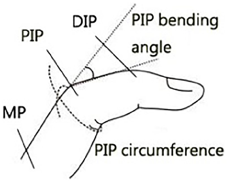
Schematic diagram of three knuckles.
The index finger was selected to research the sensing performance of conductive glove, for it is mainly used with other fingers for grasping or other actions and it has strong flexibility. According to the bending angle of the index finger PIP joint (Pba), five human hand postures in 26 Chinese alphabet sign languages16,17 was chosen and their eigenvalues were measured as shown in Table 2, including Pba, PIP joint circumference, and so on. Taking the horizontal extension line of the finger bone as the reference line, the angle between the interphalangeal bone and the PIP bending angle is Pba; 18 the length of the proximal knuckle around the index finger is the PIP circumference. The five eigenvalues are shown in Table 2, among which length and circumference were measured by tape. Five alphabet sign languages are shown in Figure 3.
Index finger’s five eigenvalues.

PIP: proximal interphalangeal joint.

The five alphabetic sign languages: (a) sign B, (b) sign C, (c) sign O, (d) sign A, and (e) sign S.
The bending angle of the PIP joint (Pba) was fitted with two feature values of finger, that is, stretch of PIP circumference and stretch of conductive area (Sca). A quadratic equation between bending angle of PIP joint and stretch of conductive area is calculated, and the equation for it is as follows

High value of R2 demonstrates a high degree of fitting.
As elastic fabric is flexible, it can fit the surface of human skin closely. When the elastic conductive glove is worn on, the sensing area made by conductive yarns as well as elastic yarns can stretch or recover with finger motion. From Figure 4 and equation (1), it can be seen this is a feasible method to show Pba condition by registering conductive area stretch.

Relationship between PIP joint angle and fabric stretch.
Static tests
The length of glove conductive area was controlled as 4 cm long after experimenter wore it each time, in order to escape the influence of forehand stretch. Static test was performed by connecting a ground resistance tester with conductive glove. The exposed ends of conductive yarn from intarsia area of glove were twisted with the ends of copper wires, as shown in Figure 1, and other ends of two short wires were clamped by the VICTORY 4105A ground resistance tester(direct current, output voltage is 12 V, measure range is 0.01–2000 Ω). A simple protractor was used to control changing the PIP joint bending angle of the index finger by 0°, 20°, 40°, 60°, 80°, and 100°, respectively. Resistance value changes were obtained by resistance tester under each bending angle, the relationship between resistance and index finger PIP joint was obtained as shown in Figure 5.

Relationship between resistance and PIP angle in static test.
According to former experiments, 19 it was found three phases exists in resistance–strain curve. Initially, resistance of knitted elastic conductive fabric would rapidly increase when stretched along wale’s direction, which is seemed as Phase 1 of its electro-mechanical property. With further stretch, the resistance was almost changeless over a period of time, which is seemed as Phase 2. Then, the conductive fabric was stretched more, resistance began to decrease, which is seemed as Phase 3, and existence of the three phases is due to change of effective contact sites between knitting loops. In this way, with bending of PIP joint, conductive area is stretched and then resistance of it changes. Therefore, it was considered to perform bending condition of finger using the Phase 1 of electrical properties of the conductive fabric.
As shown in Figure 5, highly fitted curve between angles of PIP bending and resistance was exhibited during the static test. A high possibility of showing the angle of finger joint through RCs can be seen from that.
Dynamic test
The length of glove conductive area was still controlled as 4 cm long after experimenter wore it each time. A real-time resistance collecting system made by KTC from JN University was used and 20 resistance values were collected per second for dynamic hand posture testing of conductive gloves.
Changing bending angle of PIP joint (Pba)
The experimenter repeated motion from gesture B to gesture C as shown in Figure 6, and registered the resistance–time curve using a resistance system measuring the RC in real time. Then movements from gesture B to gesture O, gesture B to gesture A, and gesture B to gesture S were also performed until all dynamic motions were completed. Each kind of motion was repeated several times to record resistance–time curves, two cycles of them were extracted to make comparison as shown in Figure 7.

Photographs of five hand postures in a curved state: (a) gesture B, (b) gesture C, (c) gesture O, (d) gesture A, and (e) gesture S.

Resistance–time curves for different dynamic changes.
Changing rate of bending (Br)
Due to sensing mechanism of weft knitted strain sensor,19,20 it is assumed that stretch rate has certain effects on sensitivity of conductive knitted fabric. Therefore, rate of bending will affect RC of glove in some way. In order to explore the influence of the finger bending rate on the RC conditions, the repeated bending motion of gesture B to gesture A is selected. Under the premise that other conditions remain the same; the experimenter makes repeated movements of different bending speeds, and observes the influence of finger movement speed on the change of glove resistance. The resistance versus time curve at different speeds is shown in Figure 8.

Resistance–time curve at different bending speeds.
Results and discussion
Dynamic test for changing Pba
By controlling Pba from gesture C to B, glove yielded resistance of up to 21 Ω, whereas when moving from gesture O to B, the resistance would increase. These resistance signals are obviously different with each other. Therefore, it is known that Pba can cause significant difference in the RC of the conductive glove, which equals the maximum value minus the minimum value during a motion cycle. Based on several cycle’s experiment data, a box diagram relating Pba and RC was made as shown in Figure 9. Four rectangles, respectively, correspond to four kinds of Pba situations. In which the uppermost line of each rectangle represents RCmax of 10 cycles in each motion and the lowermost line represents RCmin. Additional, the middle line represents the median of RC value, which is more intuitive and accurate showing numerical situation of RC. From it can be seen that RC value has a quadratic equation relationship with Pba of each motion.
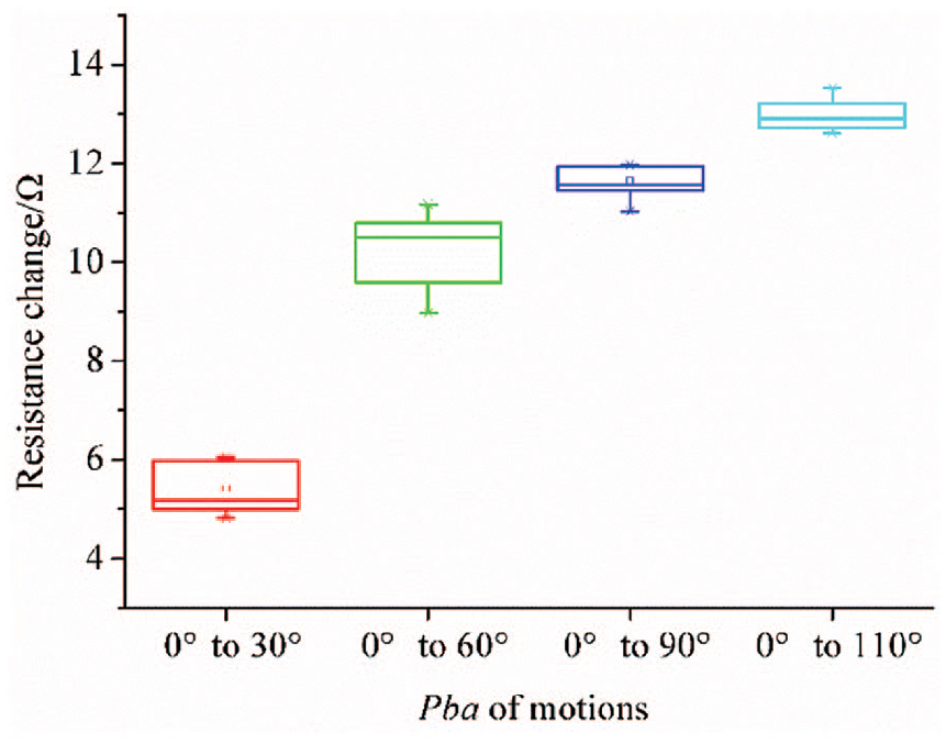
Box chart relates Pba and RC value.
Dynamic test for changing Br
It is obvious that Br has effects on both RC value and resistance change rate (RCr). Fast motion led to rapid deformation of knitted fabric. Therefore, conductive area had quick stretch, contacting force among coils increase more quickly so that whole sensitivity of it is higher. The higher the instantaneous sensitivity of the conductive area is, the greater the RC values generated during the cycles are. During this experiment, several cycles’ data having various Br were extracted to calculate RCr and average, as shown in Table 3. Then, it can be obtained that both of RC and RCr have well-fitted linear relationship with Br, as shown in Figure 10.
Tensile state values at five bending speeds.


The relationship between Br and two factors.
The fitting equations are


Since the rapid rotation of the human finger joint directly leads to rapid stretch or recovery of the conductive fabric, the average RCr over a period of time can be used to characterize Br or stretch rate during that time. It can be seen from Figure 11, the stretching rate of the index finger skin can be calculated according to the time and RC of one completed cycle, thereby determining the hand posture in the bending motion.

Five repeated cycles of motion from gesture C to gesture B.
Comprehensive analysis of two factors
During the actual finger motion, both of the stretching speed and Pba have an influence on the RC and RCr. Therefore, Pba and average stretching speed were regarded as the impact factor 1 (IF1) and impact factor (IF2), respectively, the average RCr and RC caused by the finger motion during the test were measured as the Re.1 and Re.2, respectively. The relationship between these four values was fitted using multiple linear regression equations. Sets of motions with different characteristics were selected and the relevant parameters were calculated. By the multiple regression equation fitting, the binary equations are that
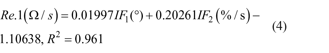

Or


It can be obtained from equations (6) and (7) that

It can be seen from the fitting results that both two impact factors have an effect on RCr and RC, and a relationship between these parameters can be obtained. By collecting time span during a period as well as RC value, that is RC, the bending angle, that is Pba is also available. While there may be still many limitations and disadvantages during this experiment or calculation, such as different experimenters may differ these quantitative results.
Repeatability
Other important features of sensors also include repeatability and hysteresis. Since there is no standard means for calculating the repeatability of textile flexible sensors,previous work 21 was used as a reference, which is one of the standards of National Standards Of People’s Republic of China. During the standard repeatability means, limit value of accidental errors of sensors is calculated as follows
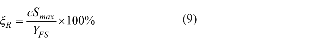
where
According to this standard, repeatability deviations of the motion form gesture C to gesture B is calculated as 9.88%, up-travel and down-travel curves of five cycles was shown in Figure 11. For the same principle, repeatability deviations of other motions were calculated as 12.02%, 17.37%, and 10.20% respectively. The repeatability is not so good, which may be caused by action difference, hence the accuracy of the motion repeat should be improved in the future.
Conclusion
In summary, fully formed conductive sensing glove has been knitted and used to monitor different states of human finger motions. Static tests indicate that the RC of the gloves is obviously affected by the bending angle (Pba) of the fingers and there is a linear relationship between them. While dynamic tests showed that both the bending angle (Pba) and rate of the finger bending (Br) have significant influences on the RC as well as RCr. Their quantitative relationship can be roughly obtained by multiple regression equation fitting. The bigger Br is, the greater RC is, and it is true for RCr too. The bigger the Pba, the greater RC is. This is all because of electrical change of knitted conductive fabric during stretch and recovery. The fabric of the conductive area has well repeatability, which can be seen from the repeatability deviation of different motions being calculated. Overall, there are still many influencing parameters need to be further discussed in the future such as circumferential strain and human individual differences, and so on.
Footnotes
Declaration of conflicting interests
The author(s) declared no potential conflicts of interest with respect to the research, authorship, and/or publication of this article.
Funding
The author(s) received no financial support for the research, authorship, and/or publication of this article.