
Abstract
Polyacrylonitrile belongs to the most often used precursors for carbon fibers. Using electrospinning, polyacrylonitrile nanofiber mats can be prepared and afterwards stabilized and carbonized to prepare carbon nanofiber mats which, by adding other materials, will be useful for several applications. One of these materials is TiO2, which has photocatalytic properties and can thus be used as a photocatalyst for photodegradation of dyes. Here, we report on a detailed study of electrospinning, stabilization, and carbonization of electrospun polyacrylonitrile/TiO2 mats with varying TiO2 content. Depending on the amount of TiO2 in the nanofibers, the fiber morphology changes strongly, indicating an upper limit for the preparation of carbon/TiO2 nanofibers with smooth surface, but offering an even increased inner surface of the rougher carbon/TiO2 nanofibers with increased TiO2 content due to better maintenance of the fibrous structure during stabilization.
Introduction
Electrospinning is a method often used to prepare nanofibers or nanofiber mats.1–3 Due to their large surface-to-volume ratio, such nanofiber mats are used for diverse applications, from filter materials4,5 to catalysts6–8 to medical wound dressing. 9 Besides pure polymers, also polymer blends or polymers with incorporated inorganic compounds can be electrospun.10–12
A polymer which has been studied often is polyacrylonitrile (PAN). On one hand, it can be used as a precursor for carbon nanofibers;13–16 on the other hand, it can be spun from low-toxic dimethyl sulfoxide (DMSO) 17 which is especially advantageous for biotechnological applications. 18
Carbonizing PAN nanofibers with included inorganic materials can be used to broaden the possible applications of such composites. TiO2 is of special interest as inorganic partner due to its photocatalytic properties.19–21 Song et al., 22 for example, used electrospun TiO2/carbon nanofiber mats to reach high photocatalytic degradation efficiency tested with rhodamine B and proved a high durability of this effect. Similarly, composites from leaf-shaped TiO2 and reduced graphene oxide with approximately 1% of reduced graphene oxide showed large photocatalytic activity. 23 However, anodes for lithium-ion batteries were produced from α-Fe2O3 grains grafted on TiO2/carbon nanofibers, 24 N-doped TiO2/carbon nanofibers were used as anodes in sodium-ion batteries, 25 and carbon/TiO2 nanofibers were used as negative electrodes for vanadium redox flow batteries. 26
Typically, TiO2/carbon nanofibers are electrospun from a solution of titanium tetraisopropoxide, solvent, and polymer.24,27 Since titanium tetraisopropoxide (Ti{OCH(CH3)2}4) is flammable and slightly toxic, however, it must be handled with care if used in a needleless electrospinning machine, spinning with high voltages up to 80 kV. Alternatively, tetra-n-butyl titanate (Ti(C4H9O)4) can be used,23,25,26 a material which is also flammable and in addition, corrosive and toxic. Only few reports can be found in the literature about coating electrospun nanofibers with TiO2 nanoparticles;28–31 however, immobilization of the TiO2 particles on the nanofiber surface is not easy.
Including TiO2 nanoparticles directly in the polymer solution is scarce. Chang et al. 32 report on needle-electrospinning from dimethylformamide (DMF) as the solvent, using a TiO2:PAN weight ratio of 1:10. While the original electrospun nanofibers show a relatively even rough surface, self-erosion of the embedded TiO2 particles results in several large holes along the fibers which become larger during carbonization. An et al. 33 investigated three different weight ratios of TiO2:PAN/PVP (from 3.4% to 13.8% of the precursor solution; the polymer content is not given) for the possible use as counter electrodes in dye-sensitized solar cells. By needle electrospinning this solution from DMF as the solvent, nanofibers with different surface roughness were gained. Electrospinning from a polyphenylene vinylene (PPV) solution containing TiO2 was reported by Wang et al., 34 resulting in rough nanofibers in a broad range of diameters.
A systematic study of the morphological changes due to inclusion of different amounts of TiO2 in polymer nanofibers, however, is still missing. The aim of this study is to thus investigate PAN nanofiber mats, needleless electrospun from DMSO—which was to the best of our knowledge not yet reported in the literature—with different amounts of TiO2 in the spinning solution. The stabilization process which is known to significantly influence the nanofiber mat morphology by modifying stabilization temperatures and heating rates 35 is examined in detail, before some exemplary nanofiber mats are carbonized at different temperatures. The changes of the nanofiber mats due to these processing steps are important to understand for all applications of carbon/TiO2 nanofiber mats, such as dye-sensitized solar cells or batteries.
Materials and methods
Nanofiber mats were produced with the needleless electrospinning machine Nanospider Lab (Elmarco, Czech Republic). The spinning parameters were as follows: high voltage 70 kV, electrode-substrate distance 240 mm, nozzle diameter 0.8 mm, carriage speed 100 mm/s, using a static substrate, relative humidity 33%, and temperature 21°C. It should be mentioned that the necessary relative humidity depends on the electrospinning technology and the electrospun polymer; in case of the Nanospider, working with a wire-based technology, a maximum humidity of 33% is ideal for spinning PAN, while higher relative humidity results in cotton-candy-like undesired structures. 17
For the spinning solution, 16 wt% PAN were dissolved in DMSO (minimum 99.9% purity; S3 Chemicals, Germany); 0–10.2 wt% TiO2 P25 nanoparticles (Degussa, Germany) were added to this solution. Solutions with higher amounts of TiO2 could not be electrospun with the wire-based technology of the Nanospider Lab.
Stabilization of the samples was performed in a muffle furnace B150 (Nabertherm, Germany), approaching temperatures from 120°C to 300°C by heating rates between 0.5°C/min and 8°C/min, followed by isothermal treatment for 1 h. Opposite to a former experiment, 35 the samples were not fixed during this process to enable investigation of the influence of the TiO2 content on the morphology change during this process. A furnace CTF 12/TZF 12 (Carbolite Gero Ltd., UK) was used for carbonization at 500°C or 800°C, approached with a heating rate of 10°C/min.
The sample morphology was investigated by a scanning electron microscope (SEM) Zeiss 1450VPSE, using a nominal magnification of ×5000. An Excalibur 3100 (Varian, Inc., USA) was applied for Fourier-transform infrared (FTIR) spectroscopy. Sample masses were taken with an analytical balance (VWR, Radnor, Pennsylvania, USA).
Results and discussion
In this section, SEM images of nanofiber mats after electrospinning, stabilization, and carbonization are shown, followed by chemical investigations using FTIR.
The first examinations concentrate on the morphology of the nanofibers. Figure 1 depicts the nanofiber mats electrospun with increasing amounts of TiO2 (Figure 1(a)–(e)). While for the lowest amount of TiO2 (Figure 1(a)), the fibers are mostly relatively smooth, straight, and regular, like pure PAN nanofiber mats,16,35 more and thicker beads become visible for higher TiO2 concentrations. These beads are typically visible if electrospinning is performed from solutions based on DMSO or other slowly evaporating solvents with relatively low solid content. Recent investigations of electrospinning PAN from DMSO with the Nanospider showed such beads for concentrations up to 15% solid content, 14 while they vanished for concentrations of 16% or higher. Here, these beads seem to be related to TiO2 agglomerations which are surrounded by the polymer, according to the relatively uneven surface of the beads visible in Figure 1(e), indicating that they contain more TiO2 than the smooth fibers.
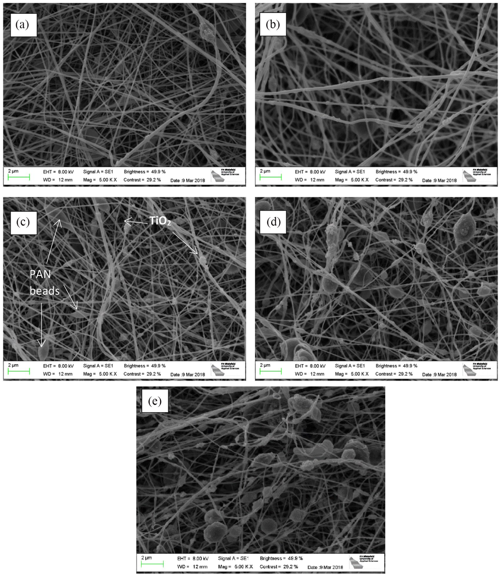
SEM images of PAN nanofiber mats with different amounts of TiO2 after electrospinning: (a) 2.2% TiO2, (b) 4.2% TiO2, (c) 6.2% TiO2, (d) 8.2% TiO2, and (e) 10.2% TiO2.
The overall fiber diameter is not visibly changed from the lowest TiO2 content (91 ± 25 nm) to the highest one (85 ± 16 nm), but the images show that the fibers are decorated with TiO2 nanoparticles or small agglomerations. It should be mentioned that in comparison with the literature, the amounts of TiO2 depicted here are relatively high (12.1%–38.9%) as compared to Wang et al. 30 (11.7%) in which the TiO2 nanoparticles were mostly embedded in the polymer fibers.
The nanofiber mats presented in Figure 1 were now stabilized at different temperatures, using a heating rate of 1°C/min. Figure 2 depicts the morphologies for a stabilization temperature of 280°C, the temperature found to be ideal to stabilize needleless electrospun PAN nanofiber mats without TiO2. 35 The samples were not fixed during stabilization which lead to a typical change of the morphology toward meandering fibers with conglutinations along the crossing points,16,35 also resulting in more visible beads per depicted area. This result is also visible here. However, here it may be recognized as a positive effect since the fiber decoration by TiO2 nanoparticles becomes more regular during stabilization. In addition, fewer conglutinations are visible in the nanofiber mats with the highest TiO2 content.

SEM images of PAN nanofiber mats with different amounts of TiO2 after stabilization at 280°C, approached with 1°C/min: (a) 2.2% TiO2, (b) 4.2% TiO2, (c) 6.2% TiO2, (d) 8.2% TiO2, and (e) 10.2% TiO2.
An interesting finding is depicted in Figure 3, comparing the nanofiber mat with the highest TiO2 content after stabilization at 280°C, approached with heating rates of 0.5°C/min and 8°C/min. While such different heating rates resulted in significantly different morphologies for pure PAN, with large conglutination areas for high heating rates, 35 here both mats look similar. Apparently, the large amount of TiO2 stabilizes the nano-structure to a certain extent, similar to the nearly complete conversation of the fiber structure by metal nanoparticles. 36

SEM images of PAN nanofiber mats with 10.2% TiO2 after stabilization at 280°C, approached with different heating rates: (a) 0.5°C/min and (b) 8°C/min.
The nanofiber mats stabilized at 280°C with a heating rate of 1°C/min were afterwards carbonized. Some results are depicted in Figure 4. As already expected from Figure 2, the strongest conglutinations are visible in the nanofiber mats with smallest TiO2 content, while for the highest TiO2 content, the nanofibers meander stronger and are obviously decorated with TiO2 nanoparticles in a relatively regular way, but have kept their original fiber structure instead of melting to form a more membrane-like structure, as it is visible for the samples with the lowest TiO2 content. Carbonized pure PAN nanofiber mats are visible in Sabantina and colleagues.16,35

SEM images of PAN nanofiber mats with different amounts of TiO2 after carbonization at different temperatures, approached with 10°C/min: (a) 2.2%/500°C, (b) 2.2% TiO2/800°C, (c) 6.2% TiO2/500°C, (d) 6.2% TiO2/800°C, (e) 10.2% TiO2/500°C, and (f) 10.2% TiO2/800°C.
For a chemical examination, Figure 5(a) depicts the results of FTIR measurements directly after electrospinning. In all samples, the typical PAN absorbance peaks are visible: a stretching vibration of the C≡N nitrile functional group at 2240 cm−1, a carbonyl (C=O) stretching peak at 1732 cm−1, ester (C–O and C–O–C) vibrations of the co-monomers like itaconic acid or methyl acrylate which are often applied in industrial production of PAN occurring in the ranges of 1230–1250 cm−1 and 1050–1090 cm−1, and bending and stretching vibrations of CH2 at 2938, 1452, and 1380 cm−1. 37 In addition, the strong peak approximately below 880 cm−1 can be attributed to TiO2.

FTIR measurements: (a) PAN nanofiber mats with different amounts of TiO2 after electrospinning; (b) PAN nanofiber mats with the highest amount of TiO2 after stabilization at different temperatures.
During stabilization, most of these peaks are exchanged by new ones (Figure 5(b)): large peaks of C=N stretching vibrations at 1582 cm−1 and C=C stretching vibration at 1660 cm−1 37 as well as C–H bending and C–H2 wagging at 1360 cm−1. 38 The peak around 800 cm−1 can be attributed to aromatic C−H vibrations originating from oxidative dehydrogenation aromatization in the presence of oxygen. 39 Comparing this stabilization behavior with the temperature dependence of pure PAN nanofiber mats, 35 no differences of the stabilized states are visible. Further FTIR measurements are thus not shown here.
The influence of stabilization temperatures between 120°C and 300°C and heating rates between 0.5°C/min and 8°C/min on the mass yield after stabilization is depicted in Figure 6. For all amounts of TiO2, masses are relatively stable in the temperature range between 120°C and 240°C. The small mass loss can mostly be attributed to a drying process. For higher temperatures of 260°C to 300°C, a higher mass loss is visible, based on the chemical stabilization process itself. This finding is qualitatively and quantitatively similar to the few available reports on stabilization temperature-dependent carbon yield of pure PAN samples or PAN/gelatin samples.35,40
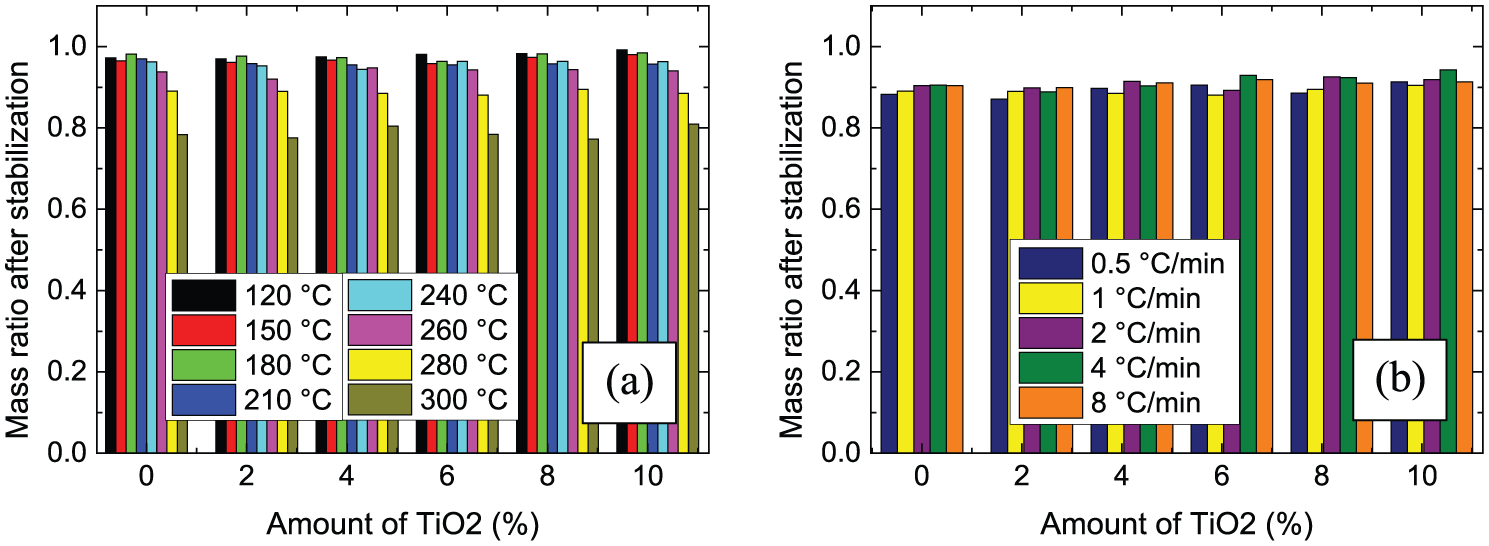
Ratio of masses after stabilization to masses before stabilization: (a) for different maximum temperatures, reached with a heating rate of 1°C/min; (b) for different heating rates, approaching a maximum temperature of 280°C.
Investigating the influence of the heating rate on the mass loss (Figure 6(b)), nearly no impact of this value is visible. Only for the lowest heating rate, slightly smaller mass ratios are visible, but the differences are not significant, similar to the previous experiments with pure PAN nanofiber mats. 35 An influence of the TiO2 concentration cannot be recognized either.
After carbonization at 500°C, a material yield of 73% ± 7% as compared to the stabilized samples (i.e. an overall mass yield of 0.64% ± 7% after stabilization and carbonization) was gained, while carbonization at 800°C resulted in a material yield of 43% ± 5% as compared to the stabilized samples (i.e. an overall mass yield of 0.38% ± 5%). No significant influence of the TiO2 content, stabilization temperature, or maximum temperature is visible for all samples under examination.
These results underline the possibility to use the prepared TiO2/carbon nanofiber mats in the above-described applications, such as front electrodes in dye-sensitized solar cells, 41 for photocatalytic degradation,19–23 and or as electrodes in different sorts of batteries.24–26
Conclusion
TiO2/PAN nanofiber mats with different amounts of TiO2 were prepared by electrospinning and afterwards stabilized at varying temperatures, approached with diverse heating rates, and finally carbonized at two different temperatures.
Despite the partly large amounts of TiO2 in the nanofiber mats, the samples under investigation behave in most cases very similar to pure PAN nanofiber mats. This is also visible within this study by comparing the samples with and without TiO2.
An interesting effect occurs with respect to the sample morphology. While the TiO2 seems to form bead-like agglomerations for larger amounts of TiO2 after electrospinning, the TiO2 becomes more and more visible also along the fibers after stabilization and especially after carbonization. In addition, higher amounts of TiO2 seem to stabilize the sample structure during stabilization. These findings are important for the applications of TiO2/carbon nanofibers in batteries or dye-sensitized solar cells, as they show that carbonization of TiO2/PAN nanofiber mats, needleless electrospun from a DMSO solution, is possible and relatively high amounts of TiO2 are even advantageous in maintaining the desired fibrous morphology, as opposed to pure PAN nanofiber mats.
Our study shows that electrospinning a blend of PAN and TiO2 offers the possibility to create mats of nanofibers decorated with TiO2 for possible use in dye-sensitized solar cells, for photodegradation of dyes, and similar applications.
Footnotes
Declaration of conflicting interests
The author(s) declared no potential conflicts of interest with respect to the research, authorship, and/or publication of this article.
Funding
The author(s) disclosed receipt of the following financial support for the research, authorship, and/or publication of this article: The study was partly funded by the HiF fund of Bielefeld University of Applied Sciences and the Junta de Andalucía for the group TEP-184. This article is funded by the Open Access Publication Fund of Bielefeld University of Applied Sciences and the Deutsche Forschungsgemeinschaft (DFG, German Research Foundation) – 414001623.