
Abstract
This study demonstrates a first example of silver nanowire coated wool fibers for wearable electronic applications. Silver nanowires were synthesized according to the polyol method and then drop casted on knitted wool fabrics. Electronic properties of the knitted samples were investigated under cyclic bending conditions. Conductive fabrics were isolated with a dielectric material and used as capacitance to measure respiration and finger motions. In addition, the same capacitor was employed as a pressure sensor and touch-based sensor for lighting up an LED. This study demonstrates that silver nanowire coated knitted wool fabrics can be used in electronic textiles not only as a flexible electrode but also as a capacitor for different applications.
Introduction
Each natural fiber has their unique properties: cotton is soft, silk is shiny, and wool is an excellent insulator. Due to these unique properties, people have been using these fibers in their daily life for ages. In our modern day, people have different requirements which cannot be compensated by the physical properties of natural fibers, such as electric conductivity. Unfortunately, all natural fibers are electrically insulators. Yet, conductivity is the key property to connect textile fibers with the requirements of current electronic applications. All modern textile applications such as wearable sensors, health monitors, posture controllers, antistatic garments, electromagnetic shielding, smart sportswear, heating clothes, military textiles, soft robotics, energy harvesting, and space suits require electrical conductivity to some extent.1–5 Thus, creating conductive textile materials is critical to meet these demands.
The first choice for creating conductive textile surfaces is using conductive materials like copper or steel wires instead of yarns. These materials are heavy and not comfortable as conventional textile materials. There are various techniques to make conventional textile materials conductive such as drop casting, film coating, electrochemical coating, chemical vapor deposition, and dipping. 6 Among these methods, dipping and drop-casting methods are the simplest methods since it only requires dipping the textile material into a solution of conductive dispersion or dropping the solution onto the textile surface with a Pasteur pipette. These methods have been used for creating conductive woven, knitted, and non-woven fabrics.7,8 Therefore, we have employed drop-casting technique in this study to create conductive knitted wool fabrics.
Organic or inorganic materials can be used to develop electrically conductive textile surfaces. Due to the presence of double bond in their backbone, conjugated polymers are electrically conductive. Direct polymerization of pyrrole or aniline on the textile surfaces has been studied. 9 Hakkansson et al. 10 demonstrated pyrrole coated polyester-Lycra® knitted fabric for heating textile applications. In another study, poly(3,4-ethylenedioxythiophene) coated warp knitted glove was utilized as a microcontroller for a robotic clipper. 11 Conjugated polymers can be embedded into fibers using wet spinning technique, as well. Seyedin et al. 12 developed knitted strain sensors using fibers produced via this technique. Wang et al. 13 deposited polypyrrole on stretchable spandex fibers through a chemical vapor deposition technique. However, this rigid conductor starts cracking only after a 6% applied strain, yielding a rapid increase in the resistance. In addition, coating the wool yarn with polypyrrole is already studied, and results show that even at high concentration of additive usage, yarn resistance was very high at megaohm levels. 14 Conjugated polymers not only have lower conductivity compared to metallic conductors but also are expensive and require tedious synthesis processes.15,16
Graphene is another organic conductive material and has several unique properties due to its two-dimensional structure. Recently, graphene was dip-coated on a non-woven fabric to produce a flexible sensor 17 and coated with water soluble poly(vinyl alcohol) (PVA) to make a stretchable supercapacitor. 18 In both cases, strong acids were used to reduce graphene oxide to graphene, which is environmentally hazardous. Silver nanowires (AgNWs), on the contrary, can be produced and applied on textile surfaces via environmentally friendly methods. AgNWs have higher conductivity and lower cost compared to graphene, graphene oxide, and carbon nanotubes.19–21 Due to these superior properties, AgNWs have been employed in this study to provide electrical conductivity to the wool fabric.
Surface scales of wool fibers provide its unique texture and its molecular structure allows formation of ionic and hydrogen bonding. 14 In this study, we have coated knitted wool fabrics with AgNWs for the first time. Due to the surface properties of wool, AgNWs were able to adhere to surface very easily after simple drop-casting procedure. We have used knitted wool fabric due to the special properties of knitting fabric. Because the knitted fabrics have good elasticity, litheness, slickness, and elastic recovery properties, they have been receiving great interests in wearable electronics applications.22–24
In this article, highly conductive and flexible knitted wool fabric is made via using a circular knitting machine. Conductivity is provided with AgNW–EtOH (ethanol) solution, which is coated over the fabric via drop-casting method. The electrical conductivity of wool fabric is tested under continuous bending and relaxing condition. Finally, we have made a capacitive sensor via isolating two conductive knitted fabrics with a thin layer of inductive material. This capacitor is employed as a touch sensor and pressure sensor as well as a wearable electronic tool for measuring the respiration and finger movements.
Experimental
Materials
Ne 60/2 100% wool yarn is used to produce the knitted fabric in circular knitting machine. Wool yarn was obtained from a local woolen yarn producer. Silicone oil, polyvinylpyrrolidone (PVP, MW of 40,000 g/mol), ethylene glycol (EG), sodium chloride (NaCl), silver nitrate, EtOH, and acetone were purchased from Sigma-Aldrich.
Synthesis of nanowire solution
Crystallizing dish with a 14-cm of diameter was placed on a hot plate with magnetic stirrer and filled with silicon oil; 2 g of PVP, 50 mL of EG, and magnet are placed into the triple neck flask and stirred at 180°C. Meanwhile, 0.5 g of silver nitrate is dissolved in 50 mL EG in a different flask. After 40 min, 150 µL of 1 M NaCl-EG solution is added into the triple neck flask and silver nitrate solution is injected dropwise with the help of a syringe pump machine. After adding the entire silver nitrate solution, PVP solution turns into a shiny gray color. After reaction reaches the room temperature, solution was diluted with acetone and washed with deionized water to remove the remaining PVP on the surface of AgNWs. AgNWs were precipitated in a centrifuge machine. Final precipitation was diluted with EtOH (1 g/20 mL) and mixed in an ultrasonic mixer for 10 min before applying onto the textile surfaces.
Preparation of the conductive fabric
Ne 60/2 wool yarn is used to produce 1 m long knitted fabric in a Faykon laboratory type circular weft knitting machine. The knitted fabric is cut in size of 1 cm × 5 cm samples before the coating process. AgNW–EtOH solution was coated on both sides of the five fabric samples with a Pasteur pipette. Then, the sample is dried in an oven for 30 min at 50°C. After drying, samples’ weights were measured and resistance values were recorded with a multimeter. This process is repeated for the second time to see the effect of additional coating on the electrical resistivity. After final coating procedure, samples are placed in deionized water for 24 h to dissolve the remnant PVP, which results in a decrease in the electrical resistance.
After the first and second coating processes, resistivity values were measured as 53.6 ± 1.8 and 5.6 ± 0.2 Ω/cm. Resistance decreases to 2.7 ± 0.1 Ω/cm after keeping the samples in distillated water for 24 h and then drying in the oven. AgNW weight content of the final sample was measured as 20% ± 0.04%.
Bending and stretchability testing
AgNW coated wool knitted fabric is placed between two grippers, which are the part of special mechanism for measuring conductivity under bending conditions. The distance between the grippers was 3.5 cm, and the resistance value was measured throughout the bending experiment with a Fluke 8845A 6.5 Digit Precision Multimeter. At the beginning of the bending cycle, grippers stay constant for 5 s and then start approaching to each other till sample forms 180° bending angle (see Figure 3(b)). Grippers stay constant at this position for another 5 s and then turn back to their initial positions. Entire bending and relaxing cycle takes 37 s and we have performed 150 continuous bending cycles.
Making capacitance using the conductive knitted fabric
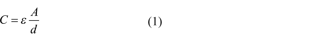
Capacitance is made via placing a 0.013-mm thick inductive Parafilm® between two conductive knitted samples. This capacitance is used as a pressure sensor, touch sensor, measuring respiration, and detecting finger movements. According to equation (1), there can be an increase in capacitance (C) due to a rise in cross-sectional area (A) and a decrease in the distance (d)
Measurements to detect the capacitance change in AgNW coated knitted fabric have been handled with Hioki IM3533 LCR Meter in Istanbul Technical University very large scale integrated circuits laboratory. This device has ±0.05% accuracy with wide measurement range (DC, 1 mHz–200 kHz, 5 mV–5 V, 10 µA–50 mA). Another feature of Hioki IM3533, which has a favor for AgNW coated knitted fabric, is that this device is built in low impedance high precision mode for testing low inductance or the equivalent series resistance of aluminum electrolysis capacitance.
Scanning electron microscope
Scanning electron microscope (SEM) images of conductive knitted fabrics is taken with TESCAN VEGA3 Scanning Electron Microscope. The microscope has 8-mm working gap and 10-kV speedup voltage. Before the SEM scans, specimens were not covered with additional conductive coating such as gold or platinum.
Results and discussion
SEM images of synthesized AgNWs according to the polyol method are given in Figure 1. Average diameter and the length of the synthesized AgNWs were measured via ImageJ software and found to be 95.3 ± 42.4 nm and 13.4 ± 3 μm, respectively. 25 These results are in good agreement with the other polyol methods reported in the literature.26,27

SEM images of AgNWs synthesized according to the polyol method: Scales bars are (a) 5 µm and (b) 1 µm.
In this study, we have coated synthesized AgNWs onto the wool knitted fabrics. As seen in Figure 2, AgNWs are thoroughly coated on the wool fibers and yarns. This intense network of AgNWs results in a low electrical resistivity. To enable higher conductivity, it is necessary to completely remove the PVP from the surface of AgNWs. This is why coated samples were left inside a distillated water bath for 24 h. After this process, samples were dried in the oven and surface resistance of fabrics decreased from 5.6 ± 0.2 to 2.7 ± 0.1 Ω/cm. Other scientific studies have reported similar decrease in the resistance following the removal of PVP in distillated water.25,28

SEM images of conductive knitting fabric after coating and washing with distilled water under (a) 60× and (b) 1000× magnifications. Scale bars are 1 mm on the left image and 50 µm on the right image.
Based on our previous study, we can clearly state that wool fibers have significantly higher affinity to AgNWs compared to spandex yarn. While the resistance value of spandex yarn was 10 Ω/cm after five coating sequences, 25 resistance of the wool sample was only 2.7 Ω/cm even after coating two times. Spandex yarn consists of multifilament and its surface is very smooth. On the contrary, surface of the wool fiber is very rough due to the presence of scales on its surface. This roughness assists formation of an AgNW network on the wool yarn, as seen in Figure 2(b), and results in a highly conductive textile surface.
Ehrmann et al. 29 used staple fiber yarn made of stainless steel fibers and polyester fibers in their study. When the steel fiber content was 20 wt%, resistance of the yarn was 525 Ω/cm. Resistance decreases to 245 Ω/cm, when the weight percent of steel fiber content was increased to 50%. AgNW coated wool yarns, on the contrary, has an average resistance of 2.7 Ω/cm when the AgNW content in the wool yarn was 20 wt%. This means wool yarn with 20 wt% AgNW has almost 200 times better electrical conductivity compared to staple fiber PES yarn with 20 wt% steel fiber yarn. Moreover, the count of wool yarn used in this study is Ne 60/2, while the counts of aforementioned steel blended yarns were Ne 29,5. Having a very fine wool yarn with excellent conductivity provides great opportunities for creating comfortable and light wearable electronic products.
AgNW coated knitted fabrics exhibit not only excellent conductivity but also flexibility. Conductive knitted samples were tested in the bending apparatus as shown in Figure 3. Samples were mounted between the grips where the initial distance between the grips was 3.5 cm. At this position, resistance value was measured as ~9.5 Ω. During the bending test, fiber, yarn, and loop positions slightly alter. This results in a slight increase in the resistance value (~11.5 Ω) initially, followed by a decrease, as seen in Figure 3(d). When a sample is fully bended (see Figure 3(b)), resistance reaches a value which is almost the same with the resistance value (~9.5 Ω) of the relaxed sample (~9.5 Ω). However, this small fluctuation does not alter the final conductivity of the sample even after 150 bending cycles. As seen in Figure 3(d), it is not even possible to differentiate the resistance values measured in the 1st cycle and in the 150th cycle. This proves that wool knitted fabric can preserve its electrical properties under constant bending conditions and makes it an excellent candidate for wearable electronic applications.
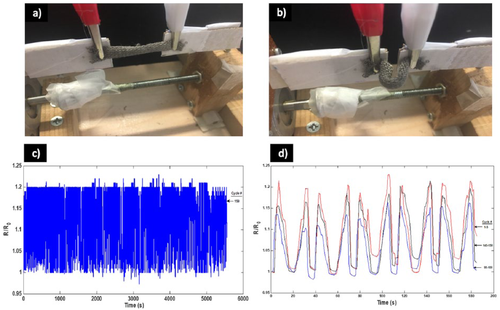
Sample is standing at (a) relax and (b) bended positions on the bending apparatus. (c) Resistance values were measured constantly throughout the bending cycles, and relative resistance versus time data are plotted. (d) Relative resistance versus time data that belong to cycle numbers 1–5, 95–100, and 145–150 were plotted for a clear view.
Creating a conductive textile material is critical to create wearable electronic applications. Since conductive knitted fabric is highly flexible, it has great potential in electronic textile applications. As a simple demonstration in aforementioned field, coated knitted sample is turned into a capacitor as illustrated in Figure 4. With the help of an Arduino microcontroller, flexible capacitor is employed as a touch-based sensor to control an LED.

Schematic illustration of flexible capacitor. Inductive Parafilm® is sandwiched AgNW coated wool knitted fabrics.
Figure 5 shows that the conductive knitted fabric is used for lighting up the LED. Arduino has analog and digital inputs and outputs on its board with ATmega328P microchip. Arduino, as the basic step, can operate a sensor as the input, and a circuit element as the output. AgNW coated knitted fabric capacitor is used as the touch sensor in this system, and a simple LED is used as the output of this system. Sample is connected to the analog inputs of Arduino board as a sensor, while LED is connected to the digital output of the board. A variation in capacitance value, such as pressing on the sample and decreasing the distance between the conductive layers, results in a change in the input. This capacitance increase in the input side can be observed by the Serial Monitor of the Arduino software on a computer. With the data difference on the input side, which is visualized on the Serial Monitor screen of Arduino software, Arduino as the microcontroller creates a change on the output side where the connection of LED with the board is achieved. As a result, touching the flexible capacitor lights up the LED. This basic step can be improved to an advanced level such as controlling a mobile device via touching our cloths. This study creates a conductive and flexible textile material for this type of future applications.
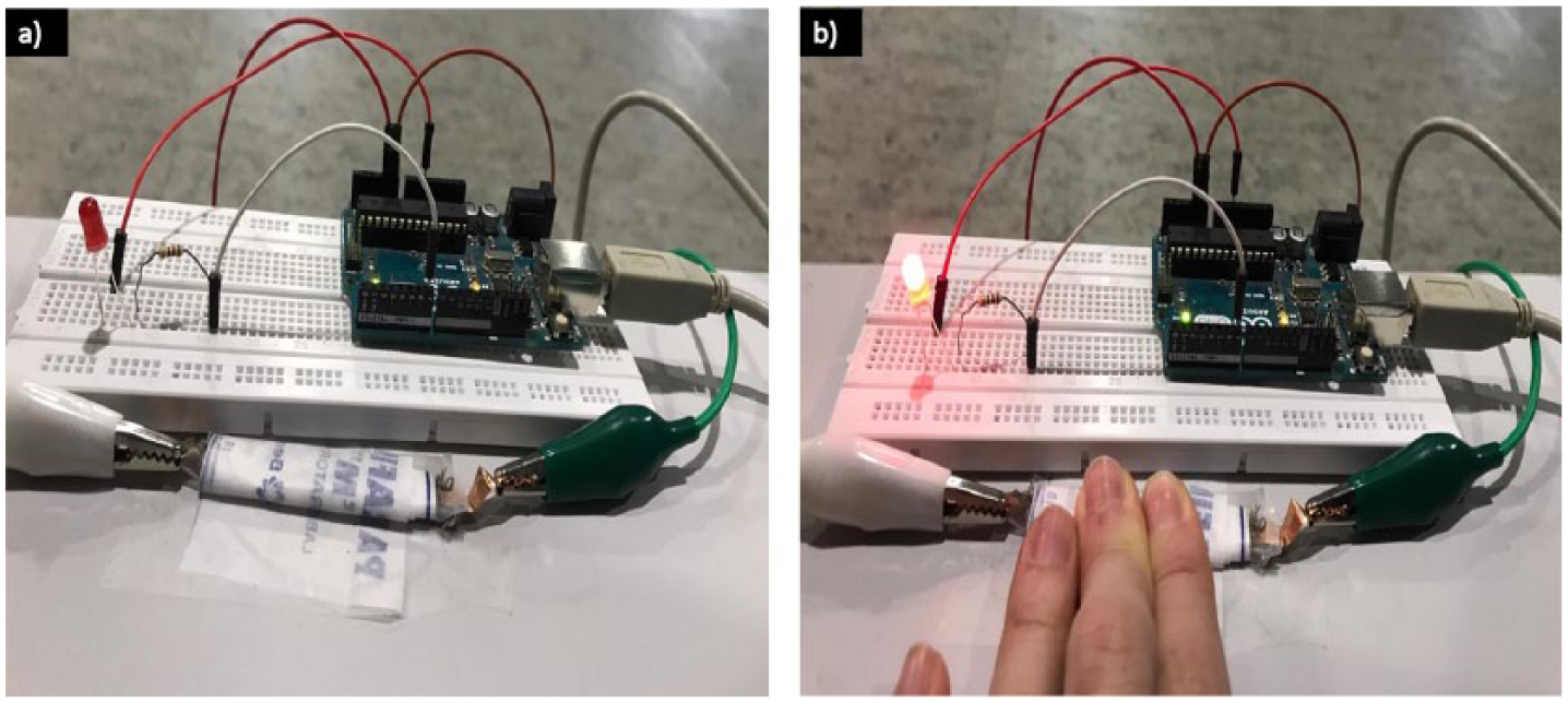
(a) Connection capacitance with touch sensor and lamp. (b) Touching the capacitance triggers the micro-controller which lights up the LED.
In Figure 6, wool knitted fabric is used as a capacitive pressure sensor for detecting different standard weights. Placing the standard weights on the fabric-based capacitor decreases the distance between the conductive layers and yields an increase in the capacitance values, as shown in Figure 6(d). Heavier loads reduce the distance between the conductive layers in a greater extent and yield a greater increase in the capacitance values; however, this increase is not exactly proportional to the weight due to the rough and porous structure of the knitted fabric.

Wool knitted fabric is used as a capacitive-based pressure sensor to detect (a) 20 g, (b) 50 g, and (c) 100 g of masses. (d) Change in the relative capacitance as a result of loading and unloading is plotted.
Since our conductive knitted fabric is very flexible, a capacitor schematically illustrated in Figure 4 is employed for detecting body motions. For example, the capacitive sensor is placed on the palm side of the middle finger. When the person squeezes his hand (Figure 7(b)), capacitance value increases and then turns back to capacitance value when the person returns his hand to its first position (Figure 7(a)). Repeating this motion results in a saw-like capacitance versus time graph, as seen in Figure 7(c). A similar technique can be employed to monitor other body joints such as wrists, elbows, and knees.

(a) Knitted conductive sample–based capacitor is attached onto the palm side of the middle finger, and (b) squeezing the fingers yields an increase in the capacitance value. (c) This increase and decrease can be detected from the capacitance versus time plot.
Finally, conductive knitted fabric is employed for detecting human respiration. Top and bottom layers of the capacitor were connected to a multimeter, and the capacitor is mounted around the abdomen (Figure 8(a)). Inhale and exhale movements alter the volume of the abdomen. Inhaling is slightly elongating the capacitor, yielding an increase in the capacitance value. As seen in Figure 8, capacitance is around ~2.4 × 10⁻¹² F in the exhale position and increases to ~3 × 10–12 F in the inhale position. Notice that increase in the capacitance value is much higher while squeezing the middle finger. This is related to higher elongation in the squeezing movement. This result suggests that coated knitted fabric–based capacitor can be used as a strain gauge application.

(a) Conductive knitted sample–based capacitor is wrapped around the abdomen and attached to a multimeter and (b) capacitance data are collected for 60 s and plotted.
Conclusions
In conclusion, wool knitted fabric is coated with AgNWs for the first time. Wool yarns demonstrate excellent affinity to the AgNWs. Coated samples are not only highly conductive but also exhibit constant resistivity after 150 bending cycles. Knitted fabrics are transformed into capacitors to serve as a touch-based sensor. Touch-based sensor is used for lighting up an LED and can be used in many other wearable electronic applications using this simple principle. Capacitor made of knitted fabric can detect 20, 50, and 100 g of weights and can be used for monitoring the body motions such as movement of the joints and respiration from the abdomen.
Footnotes
Acknowledgements
We would like to acknowledge Prof. Dr. Emel Önder Karaoğlu for kindly giving permission to us to use her Fluke 8845A 6.5 Digit Precision Multimeter.
Declaration of conflicting interests
The author(s) declared no potential conflicts of interest with respect to the research, authorship, and/or publication of this article.
Funding
The author(s) disclosed receipt of the following financial support for the research, authorship, and/or publication of this article: This study is founded by the European Commission’s Marie Skłodowska-Curie Actions, Individual Fellowship Program under Grant Agreement ID: 739891.