
Abstract
Carbon fiber braids are widely applied in various industrial fields as structural components. However, using braiding machines to braid carbon fibers is an emerging technology, but some technical problems must be solved. For instance, carbon fibers are easily fluffed when using traditional carriers; with increasing braiding speed, the machine fiercely vibrates. To investigate these problems, an improved mechanical structure of the carrier is designed, which reduces the friction between the carbon fiber and guide hole and changes the carbon fiber storage quantity. Based on the carrier, the corresponding mathematical model of the tensioning system is established by the dynamical equations, and numerical analyses and simulations are carried out. Moreover, the validation of the established mathematical model is verified. According to the results of the simulation, the fluctuation in the tensioning force is smaller than that in previous studies, and the trend is in accordance with previous research results. As a result, the present model provides a better description of the dynamic process of carbon fiber braiding.
Introduction
Braiding machines are widely used to form textile products, ropes/tubes, and other structural or composite components. The traditional braided fabric consists of yarns. However, along with the greater demands in aerospace, vehicle and other industrial engineering applications, new types of braided fabric are needed. Braiding machines are urgently needed to braid carbon fibers, glass fibers, or ceramic fibers for use as braiding materials to form products. However, these new types of fibers are not easily braided because their mechanical performance is quite different from that of yarns. For instance, carbon fibers are easy to fluff and fracture, if a traditional braiding machine is used. Glass and ceramic fibers are fragile to braid. Braiding machines must be investigated and changed to use these fibers.
Some studies have been performed on the braiding machines or braiding process.1,2 Guyader et al. 3 studied the adapted relationships between the process parameters and the braid shape by considering the transitory and steady-state process stages with differential geometrical methods. Potluri et al. 4 investigated the rapid development of braided preforms by using a geometrical simulation, which consists of the number of yarn carriers, the rotational speed of carriers, the take-up speed and the effective perimeter of the cross-section of a mandrel. Bigaud et al. 5 studied the main parameters of the braiding process and the mechanical properties of the 3D braided composites. Zhou et al. 6 analyzed the transverse impact responses of a 3D circular braided composite from the aspect of different braiding angles. Heieck et al. 7 calculated the cover factor of braided carbon fiber preforms and proposed a method for calculating the cover factors. Van Ravenhorst and Akkerman 8 proposed an inverse kinematics-based procedure to simulate the braid angle and later established a model that includes the yarn interaction, assuming an axisymmetric biaxial process with a cylindrical mandrel and Coulomb friction, and obtained the automatic generation of machine control data. Recently, these authors have published a procedure for relating the braid patterns to spool patterns, which could simulate and optimize some features of the braiding processes. 9 Goseberg et al. 10 and Lepperhoff 11 also analyzed the relationship between the carrier arrangement and the different pattern types. Kyosev and colleagues12,13 presented modeling algorithms and process simulation results for 3D braiding machines.
Most of the above studies intended to establish the relationship between the general processing characteristics and the parameters of braids. In addition, some important factors affect the properties of braids, such as the yarns’ processing behavior and the tensioning system. Ebel et al. 14 carried out a bench test to investigate the yarn damaging mechanisms of the processing behavior of different yarns. Mulvihill et al. 15 and Cornelissen et al. 16 studied the friction between carbon fibers and guide parts. Branscomb studied the yarns’ processing behavior of the net shape preforms of different yarns.
In fact, yarn damage is caused by rewinding, the spool, the carrier, yarn nets, and so on. The inner structure of the carrier itself also influences the carbon braided fabric and cannot be ignored. In particular, while braiding carbon fibers, the yarn tension, the amount of releasing/receiving yarn in each loop, and their fluctuations could result in severe yarn damage. However, few studies have focused on these aspects. Ma et al. 17 investigated the traditional carrier by separating the braiding process into several kinematic regions. However, no systematic modeling has been established. In the article, the braking system of the carrier is not clearly revealed, which could control the carbon fiber to not fluff or fracture. In particular, when analyzing the releasing region, the carrier system is simplified to a model, which does not reflect how the inner structure influences the tensioning system. In fact, the releasing region is very complex, but important to designers. However, the model is not suitable for studying braiding carbon fibers because the end point of the carrier is fixed with a yarn hole, which could damage the carbon fibers.
Improving the traditional carrier and establishing a carbon fiber–suited model is worthy and has practical value. This article aims to establish systematic kinetic equations of an improved carrier to illustrate the tensioning system.
Mathematical modeling
Mechanism of carrier
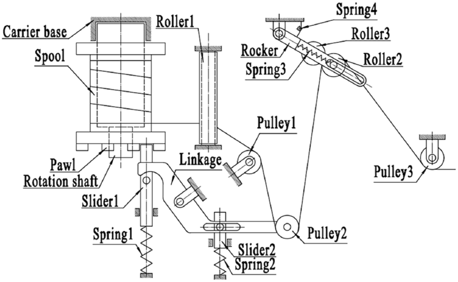
Commonly, a yarn carrier has a guide hole at the exit side, leading the yarn out from the carrier. As discussed above, this setting is unreasonable for carbon fibers. To braid carbon fibers, an improved mechanical structure of the carrier is designed, as shown in Figure 1. In this structure, the exit side is replaced by two rollers and some other components. One of the rollers is fixed on the rocker, and the other is pulled by two extension springs. The rocker could rotate around a pin fixed on the carrier with a bidirectional torsion spring. All springs have different pretension forces according to the parameters of the tensioning system.

Improved mechanical structure of the carbon fiber–suited carrier.
To investigate the mechanical principle of the tensioning system, the corresponding mechanical schematic diagram is depicted in Figure 2. As shown, a carbon fiber is released by the spool, which can rotate around the rotation shaft fixed on the carrier base. Then, the carbon fiber orderly passes over roller1, pulley1, pulley2, and roller2. The fiber will be removed from pulley3 and will ultimately arrive at the braiding point. Roller1, pulley1, and pulley3 are fixed on the carrier base. Pulley2 is a movable pulley fixed on a rotatable linkage. Roller2 can move along the groove on the rocker restrained by spring3. Figure 2 describes the initial status of the tensioning system. At this moment, there is no tensioning force in the carbon fiber. The spool is ratchet-locked. A clearance between the linkage and slider1 is set.
Schematic diagram of the tensioning system with a zero tensioning force.
Commonly, the carbon fiber is constrained by a robotic or mechanical arm at the end point. Accompanying the braiding, pulley2 and roller2 are lifted, and spring2 and spring3 are stretched. While the linkage turns at an angle
Dynamical equations of the tensioning system
To analyze the tensioning system, a schematic diagram of the tensioning system with maximal tensioning force is drawn in Figure 3. Because the dynamic characteristics of this tensioning system are periodic, only one period will be investigated. Here, the rotational point of linkage is defined as the original point. The other parameters are assigned as follows:
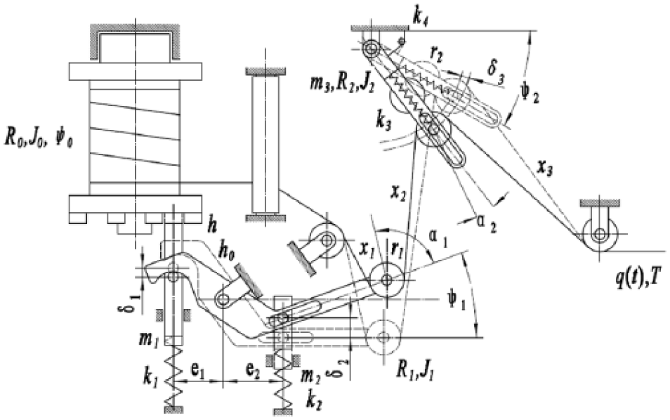
Schematic diagram of the tensioning system with the maximal tensioning force.
Generally speaking, the dynamic motion of the carrier system could be divided into three periods: the preparation period, the releasing period, and the tightening period. During the preparation period, the tensioning force

where
Slider1, slider2, linkage, roller2, and the rocker are separated from the system (Figure 4), and according to Newton’s law of motion, the following dynamical equations can be obtained

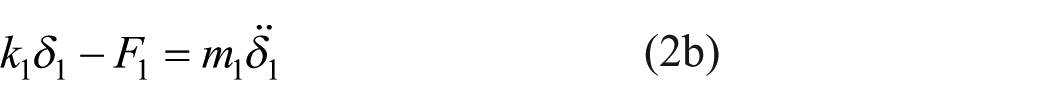
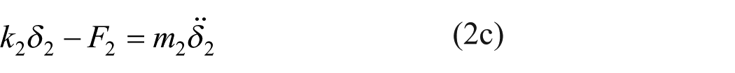


where
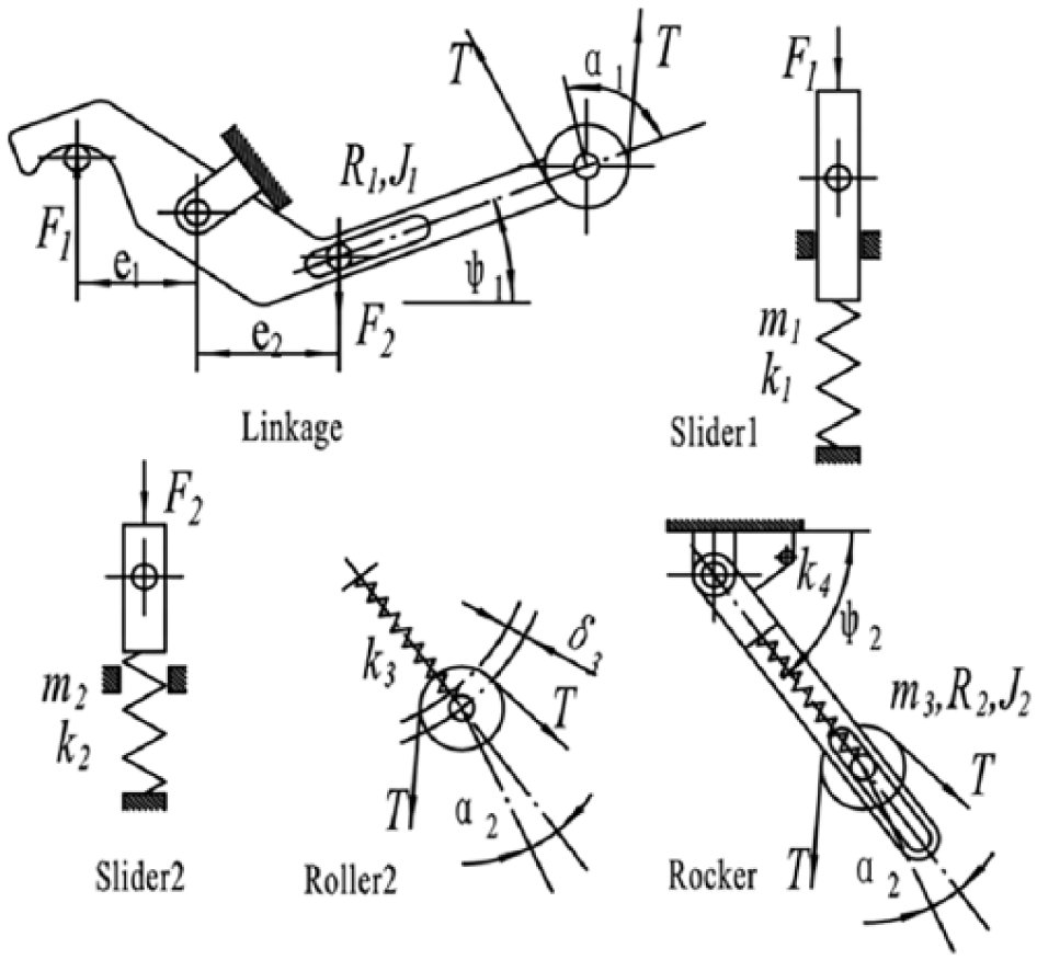
Force analysis diagram of the key parts.
By analyzing the geometrical relationships of the components (Figure 5),


where
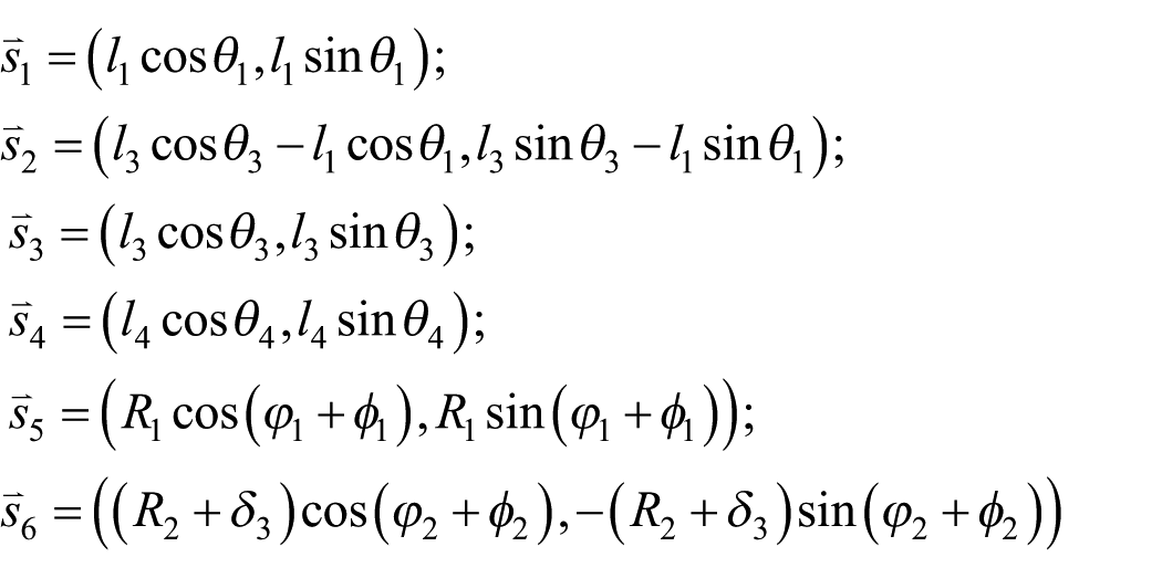

Geometrical relationships of the components.
Substituting equations 3(a) to (e) into equations 2(a) and (b), the following relationship can be obtained


where

On the contrary, the storage length of the carbon fiber is divided into three parts, which can be expressed as


Therefore, the right side of equation (1) could be expressed as a function of
It can be easily observed that the process consists of several piecewise functions. To clearly illustrate the process, a schematic graph of the tensioning force is depicted in Figure 6. Dynamical equations of each period will be discussed.

Schematic graph of the tensioning force.
To solve the dynamical equations, the boundary conditions of each period are discussed as follows. Because the traction manipulator keeps moving at a constant speed
In the preparation period, once the tensioning force overcomes the preload force of either spring1 or spring4, that is,


where
With the initial conditions,
When


where
With the initial conditions,
When


where
With the initial condition,
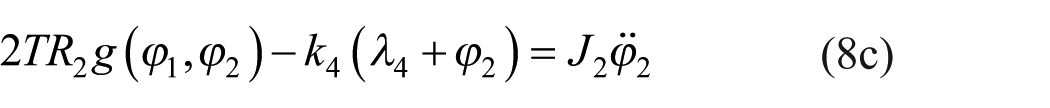
When


where
With the initial conditions,
When


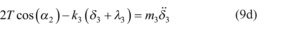
where
With the initial conditions,
When
The tightening period passes, and the system meets the initial condition of the releasing period, that is,
Numerical results and discussion
According to practical engineering, the parameters are assigned as follows:
The value of the tensioning force,

The rotational angle of the linkage,

The rotational angle of the rocker,

The defection of spring,
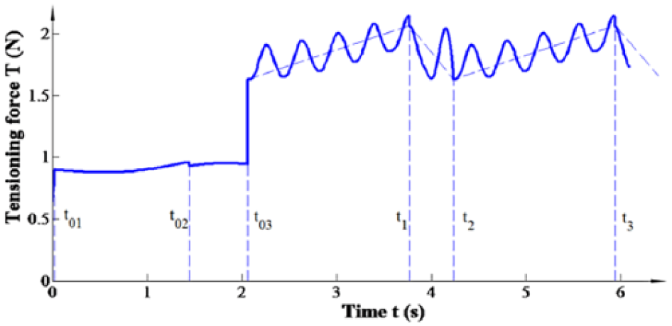
From Figures 7 to 10, initially, the yarn tension has to overcome the prestress of Spring4, which is approximately 0.63 N. From this time, the rocker starts to move, and the yarn begins to be dragged forward.
During the period from 0 to t01, the tensioning force climbs until it overcomes the prestress of Spring2, which is approximately 0.89 N. From t01, the linkage starts to move, pushing Slider2 to move upward.
During the period of t01 to t02, the tensioning force gently changes between [0.87 N, 0.96 N] until the rocker reaches its extreme position (–0.07 rad). This singular point leads to a quick drag of the yarn, causing a sudden tension drop from 0.96 N to 0.93 N. In addition, the rotational angle of the linkage changes from 0.055 rad to 0.027 rad.
During the period from t02 to t03, the tensioning force changes between [0.94 N, 0.95 N] until it overcomes the prestress of Spring3, which is approximately 0.94 N, causing a sudden tension climb from 0.94 N to 1.6 N. From t03, roller2 and roller3 start to move.
During the period from t03 to t1, the tensioning force fluctuates and gradually rises from 1.63 N to 2.14 N until it overcomes the prestress of spring1. The linkage pushes slider1 to move downward. At time t1, slider1, and the pawl are separated, and the spool starts to release the yarn.
During the period of t1 to t2, the tensioning force drops to 1.64 N, then rises to 2.04 N, and drops to 1.63 N. After the fluctuation, the releasing is completed.
During the period from t2 to t3, the change in the tensioning force is the same as that from t03 to t1, and then it loops.
The tensioning force exhibits sudden changes while the external conditions are altered. These changes bring vibration to the traction manipulator. Every sudden change in the tensioning force will lead to a shock to the traction manipulator. Thus, with an increasing braiding speed, the frequency of the shocks increases. Because there are hundreds of carriers in a large braiding machine, the shock cannot be ignored. For example, in a large braiding machine with a 440-carrier, the shock is approximately 400 N.
To verify the validation of the present model, dashed lines connecting each initial and end dot of each period were drawn in Figure 7. The trend of the tensioning force is in accordance with the experimental results in the literature. 1 Compared to the traditional carrier, the fluctuating value of the tensioning force in the present carrier falls to a ratio of 10.9%, which is obviously smaller than that of the abovementioned article. However, the fluctuating frequency climbed. Furthermore, sudden changes can be found in Figures 8 and 9. However, the rotational angle of the linkage and rocker do not indicate sudden changes because the braiding speed is assumed to be constant in the dynamical equations, which is a fluctuating value in practical engineering.
Conclusion
In this article, an improved carrier was proposed to adapt the braiding for carbon fibers. The mathematical model was established and verified by numerical analysis and previous studies. The results show that the present model reduces the fluctuating value of the tensioning force. Moreover, the tensioning force exhibits sudden changes if the traction manipulator maintains a constant braiding speed. This conclusion provides a good explanation for the vibration of traction manipulators in practical engineering. If the vibration is reduced, then the braiding speed could be increased, leading to improved productivity.
Therefore, the next study could focus on optimizing the parameters to reduce the sudden changing value of the tensioning force. Alternatively, a tension controller could be added at the end of every carrier. On this occasion, the braiding speed will change with time. This change means that the braided pitch length changes, which will influence the mechanical properties of the carbon fiber preform. Designers should check whether this change is permitted.
Footnotes
Declaration of conflicting interests
The author(s) declared no potential conflicts of interest with respect to the research, authorship, and/or publication of this article.
Funding
The author(s) disclosed receipt of the following financial support for the research, authorship, and/or publication of this article: This work was supported by the Program of Jiangsu Innovative Talent under grant [20171122] and the Fundamental Research Funds for the Central Universities under grant [2232019D3-31].