
Abstract
This paper presents a multi-threaded approach for the distributed calculation of all collision-free, unique switch states and carrier arrangements for maypole braiding machines with rectangular horn gear configurations, taking into account reflection and rotation. The algorithm is based on a sequential four-stage approach. In this approach, the configuration of horn gears, switch states, track layouts and carrier arrangements are enumerated in consecutive order, building on each other. The individual stages consistently employ rotational and mirror-symmetrical simplifications. The calculation of switch states, track layouts and carrier arrangements is performed in parallel on a single CPU with multiple threads and synchronised by a main thread, thus enabling calculation on commodity hardware. Using the novel algorithm presented here, all collision-free carrier arrangements can be enumerated. Based on this, an initial quantitative evaluation was conducted of the braids that can be produced on Maypole braiding machines with 4 × 4 horngears. The comprehensive description of all collision-free carrier arrangements is the basis for a mathematical and data-driven analysis of modern Maypole braiding machines.
Introduction
Braiding is one of the oldest cultural techniques. This is documented for the European continent by archaeological artefacts found in the caves of Santa Maria (Valencia, Spain), which date back to 12,730–12,710 cal BC. 1 The same is true for the American continent. At Monte Verde in Chile, finds dated between 13,565 ± 250 B.P. and 11,790 ± 200 B.P. document the early use of braids. 2 In 1748, Thomas Walford in Manchester, England was granted the first patent (No. 638) for a braiding machine.3,4 A few years later (1880), the first braiding machine was industrially produced in Germany, in the town of Barmen. 5
Round braids (e.g., cords) and flat braids (e.g., strands) were the first braids produced by hand or machine. Round braids are generally referred to as one-dimensional (1D) and flat or tubular braids as two-dimensional (2D). 6 For the production of three-dimensional braids (e.g., T-shaped braids), new braiding machines have been developed.7,8
One of the most widely used commercially available braiding machines with controllable switches is the variation braider from Herzog. 9 The standard version has 16 horn gears with 4 slots each. These are arranged in a square in four rows and four columns with a total of 24 controllable switches.
Various braids that can be produced are known for this and similar braiding machines. This knowledge is available in the form of pattern books,10–13 none of which contain an exhaustive list of all static braids that can be produced collision-free on a
Specifically, we make the following contributions: (1) We present a computational method that can be used to generate all connected rectangular horn gear configurations for braiding machines with up to (2) We also present an algorithm that, based on the configuration of the horn gears, generates all switch states that are unique under reflection and rotation, while preserving the interconnected structure of the horn gears. (3) In addition, we provide a method to generate all connected track layouts that are unique under reflection and rotation, where track layouts consisting of a single cycle must have at least one self-intersection. (4) Carriers can collide with each other at the transition points between the horn gears. Finally, we present a method to enumerate all collision-free maximum carrier arrangements that are unique under reflection, rotation, and permutation with at least three carriers, thus providing a comprehensive list of all collision-free arrangements.
Related work
This section provides an overview of the current state of the art with regard to the collision-free arrangement of carriers. It highlights that the approach we have developed represents a significant innovation. The research described in this publication provides a new foundation for the advancement of knowledge in both the field of braiding and the engineering of braiding machines.
Zhuo et al. 17 present a model for the collision-free positioning of carriers for circular braiders with multi-layered horn gears. In order to achieve this, the authors divide the paths into segments, based on the orthogonal arrangement of the horn gears, with four slots each.
The method presented is designed for use with circular braiders that employ static braiding paths. The calculated solutions are contingent upon the initial conditions selected and do not fully account for the solution space, as only a subset of all potential solutions are calculated.
In their publication, Chengjie et al. 14 present a mathematical model that can be used to determine collision-free carrier arrangements for rectangular rotary braiders with static trajectories. To achieve this, the various closed trajectories are subdivided into sections based on the slots of the horngears. Subsequently, collision-free carrier configurations are calculated for these sections. According to the authors, one issue is that the mathematical model has two parts, which makes its calculation complicated and time-consuming. In contrast to our approach, only a subset of the solution space is calculated.
In their standard work, which was previously used for training in Germany, Goseberg et al. 10 investigate the relationship between the pattern of the braid and the carrier occupation. In particular, they analyse the occurrence of repeating patterns in symmetrical braids and formulate rules to describe these patterns. However, they do not calculate the solution space for any type of braiding machine.
In their study, Van Ravenhorst and Akkerman 18 examine the correlation between plaiting patterns and carrier occupation. The methodology presented is based on the observation that the removal of a carrier results in the deletion of a row or column of the plaiting pattern matrix. The work also employs bit vectors to describe carrier occupation, with these being specified separately for each cycle of a track layout. The work exclusively considers circular braiding machines, and the solution space of these is not calculated, nor is an algorithm for enumerating carrier occupations presented.
In his book, Kyosev 19 describes the fundamental relationships between carrier occupancy, horngears, their slots and the structure of the resulting braid. The focus is on symmetrical carrier occupation along the braiding tracks. The considerations are suitable for different braiding machine geometries, but remain with their focus on the relationship between the pattern of the braid and the arrangement of the carriers. An algorithm for calculating the solution space is not discussed.
The Stents4Tomorrow 20 research project not only investigated electromagnetic switches and electronic bobbins, but also the continuous camera-based comparison of theoretical and actual braiding patterns. For this purpose, all possible configurations of bobbin movements for different braiding patterns were empirically determined for tunnel braiding machines. In contrast to our approach, only a few collision-free path configurations are listed and the method is restricted to tunnel braiding machines.
Engels,21,22 in his influential standard works, describes different types of braid structures. He considers different braiding machines with different geometries and then presents standard braids for each. An exhaustive list of all collision-free carrier arrangements for a particular braiding machine is not included.
In his work, Lepperhoff 23 examined the relationship between braid pattern and carrier arrangement, thereby establishing several foundational principles of braiding. However, his research did not include an enumeration of all possible carrier arrangements.
In his work, Figge 13 provides illustrations of various braiding machines with different carrier arrangements, and also provides accompanying drawings of the resulting braids. The work was produced as training material, the purpose of which is to present various braiding machines and braids by way of example; it does not provide a systematic listing of all possible braids.
A list of related work, showing the machine type aimed for and how the solution space is covered.
Visual nomenclature of the target braiding machine class
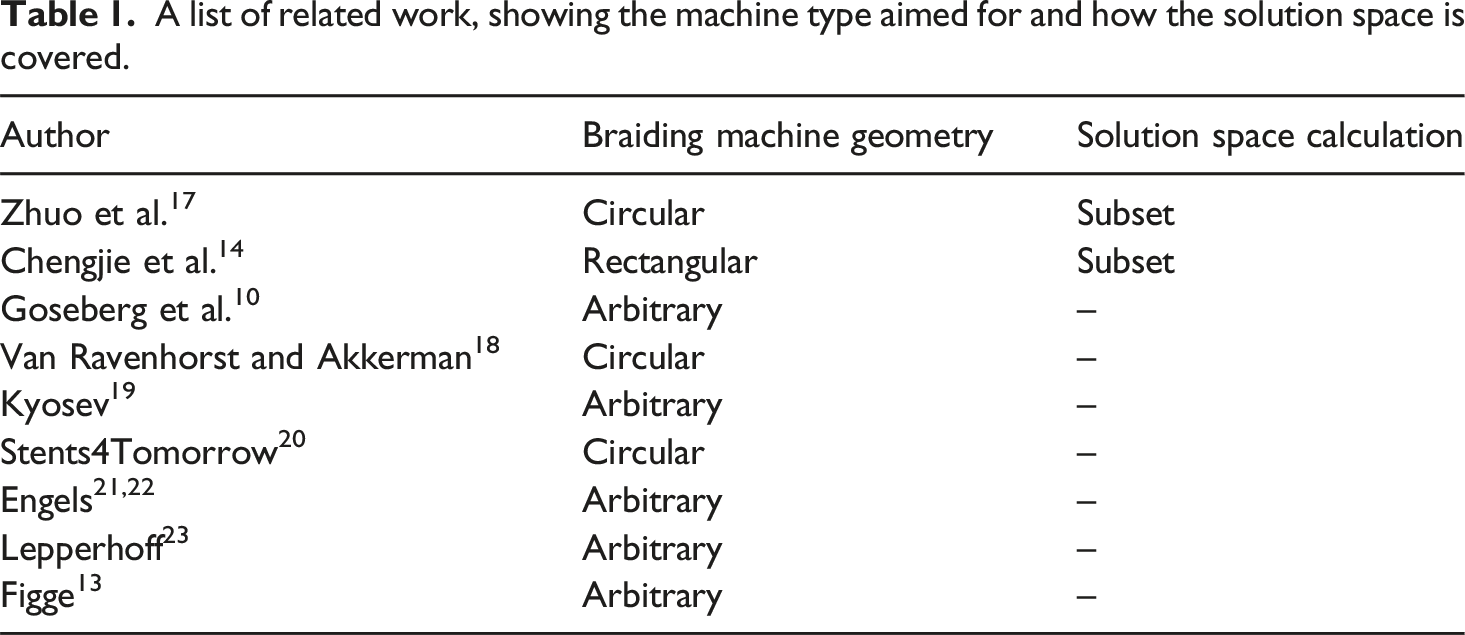
In this article, we only refer to Maypole braiding machines with rotating horn gears, a rectangular structure, and an equal number of slots on each horn gear. Figure 1 shows a diagram of such a machine. The horn gears transport the carriers along the curved paths cut into the machine bed. These paths can be modified using the built-in controllable switches. Each switch can be controlled individually to determine whether the carriers remain on the same horn gear or are transferred to the adjacent one. Drawing of a maypole braiding machine and the resulting braid based on Gries et al
3
.
We use the following visual nomenclature to illustrate this article. Unnecessary details have been omitted from selected illustrations to improve readability. Figure 2 illustrates a horn gear with four slots. The direction of rotation is indicated by an arrow in the top centre. The centre is represented by the small dark circle in the middle. Visual notation of a horn gear (left) and of two switches (right).
Switches are represented by a circle containing two straight lines. If these lines are parallel, the switch is in the ‘rotary’ state. If the lines cross, the switch is in the ‘transfer’ state.
The set of possible braids is unknown
The number of static braids that can be produced with a modern variation braiding machine is still unknown. In this context, the term “static” is used to describe the ability to produce a braid of any length without the use of a switch. Currently, the manufacturability of each new braid is verified on an individual basis. However, the proof of the negative case, namely that a braid with specific properties cannot be produced by a given braiding machine, can only be established through exclusion, which necessitates the enumeration of all feasible braids.
This publication represents a preliminary investigation into this problem and addresses the following question.
What algorithm can be utilised to efficiently enumerate all
collision-
free
, under reflection and rotation, unique switch states and carrier arrangements for maypole braiding machines with a rectangular horn gear arrangement?
Brute force is not the answer
Given the magnitude of the problem space, it is not feasible to enumerate all potential switch states and carrier arrangements for a given variation braider.
A variation braiding machine with A rectangular braiding machine with 


The number of switch positions, denoted by

It is not feasible to perform a brute force calculation for braiding machines with
Applicability and practical value
The tracks and carrier arrangements identified by our novel algorithm serve as a database for users and scientists, on the basis of which new braids can be developed more rapidly and thus more cost-effectively. Furthermore, our work provides the basis for the design of braiding machines with new horn gear configurations. Additionally, it is feasible to reduce the number of switches while maintaining the target solution space for maypole braiding machines (cf. Figure 4). In addition, listing all collision-free carrier assignments provides a basis for identifying collision-free transformations between different carrier arrangements. By identifying track layouts and carrier assignments that can be translated into each other by toggeling a switch and turning the horn gears, collision-free transitions between different carrier arrangements within the solution set identified in this article can be specified (cf. Section “Conclusions and Outlook on Future Work”). (Left) A braiding machine for manufacturing round braids. (Right) A braiding machine for manufacturing four-track square braids. In order to manufacture both types of braid using the same machine, the orange-marked switches must be configurable.
Our novel algorithm to enumerate all carrier arrangements
As demonstrated in the previous section, employing a “brute force” strategy for enumerating all carrier arrangements is not a feasible approach.
In order to calculate all carrier arrangements in a reasonable time frame of approximately 24 h, as presented in Section “Conclusions and Outlook on Future Work”, we exploit a combination of rotational and reflective symmetries, and consistently combine redundantly occurring structures (cf. Figure 5). The braiding machine with switch state and five tracks (on the left) has three non-overlapping tracks that are distinct in terms of reflection and rotation (on the right). The switches are represented by small circles. The “rotary” state is symbolised by two parallel lines and the “transfer” state by two crossed lines.
To achieve this, we employ our novel approach, which is outlined in the following section. Our approach is based on four successive stages, which are executed sequentially, with the outputs of one stage being used as the input for the subsequent stage. The calculation steps of each stage can be executed in parallel, allowing for efficient execution on common multi-thread systems.
The proposed algorithm comprises the following four steps:
1. Enumerate all rectangular horn gear configurations that are unique under reflection and rotation, up to size Under reflection and rotation, unique rectangular horn gear configurations with a maximum dimension of 
2. Identify and enumerate all, under reflection and rotation, unique switch states (cf. Figure 7) that preserve the structure of the horn gear configuration and prevent it from fragmenting into substructures (cf. Figure 15). Described in Section “Enumeration of all switch states”. Example of, under reflection and rotation, unique structure-preserving switch states for three selected horn gear configurations. The large circles represent horn gears, while the light small circles represent switches in the “rotary” state. The dark small circles symbolise switches in the “transfer” state.
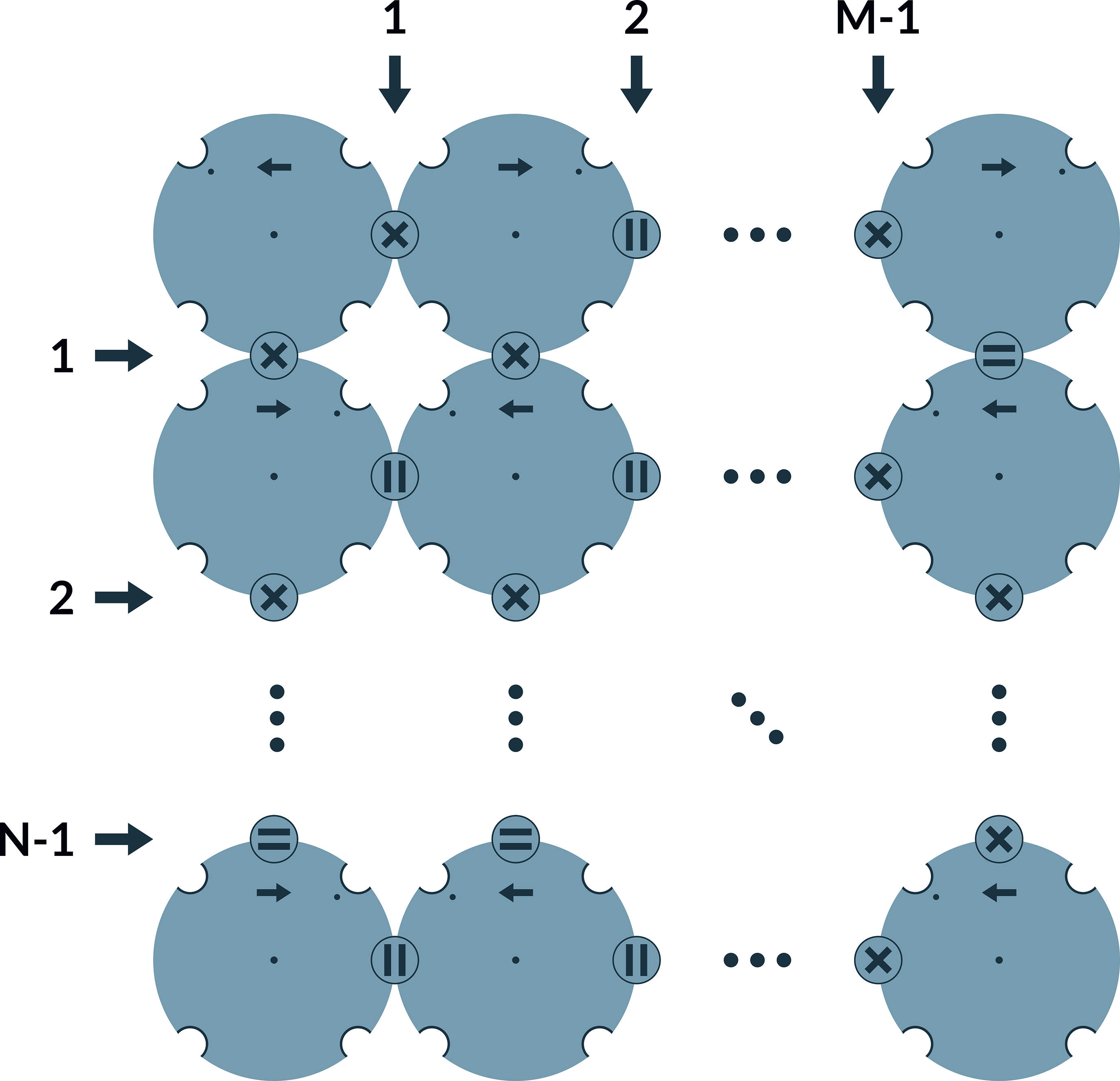
3. Translate the horn gear configurations and their switch states into track layouts. Identify all cycles and enumerate all combinations of these that are unique under reflection and rotation (cf. Figure 8). Discard trivial layouts with only one cycle without self-intersections. These would produce a twisted rope with no crossing strands, analogous to a single horn gear. Described in Section “Enumeration of all track layouts”. Example showing, under reflection and rotation, unique track layouts consisting of one self-intersecting or multiple cycles for three selected horn gear configurations with switch states.
4. Enumerate all maximum carrier arrangements that are unique under reflection and rotation (cf. Figure 9). Two carrier arrangements are considered equivalent if they can be mapped onto each other by rotating the horn gear configuration. Described in Section “Enumeration of all carrier arrangements”. Example of unique maximum carrier arrangements under reflection and rotation for selected track layouts.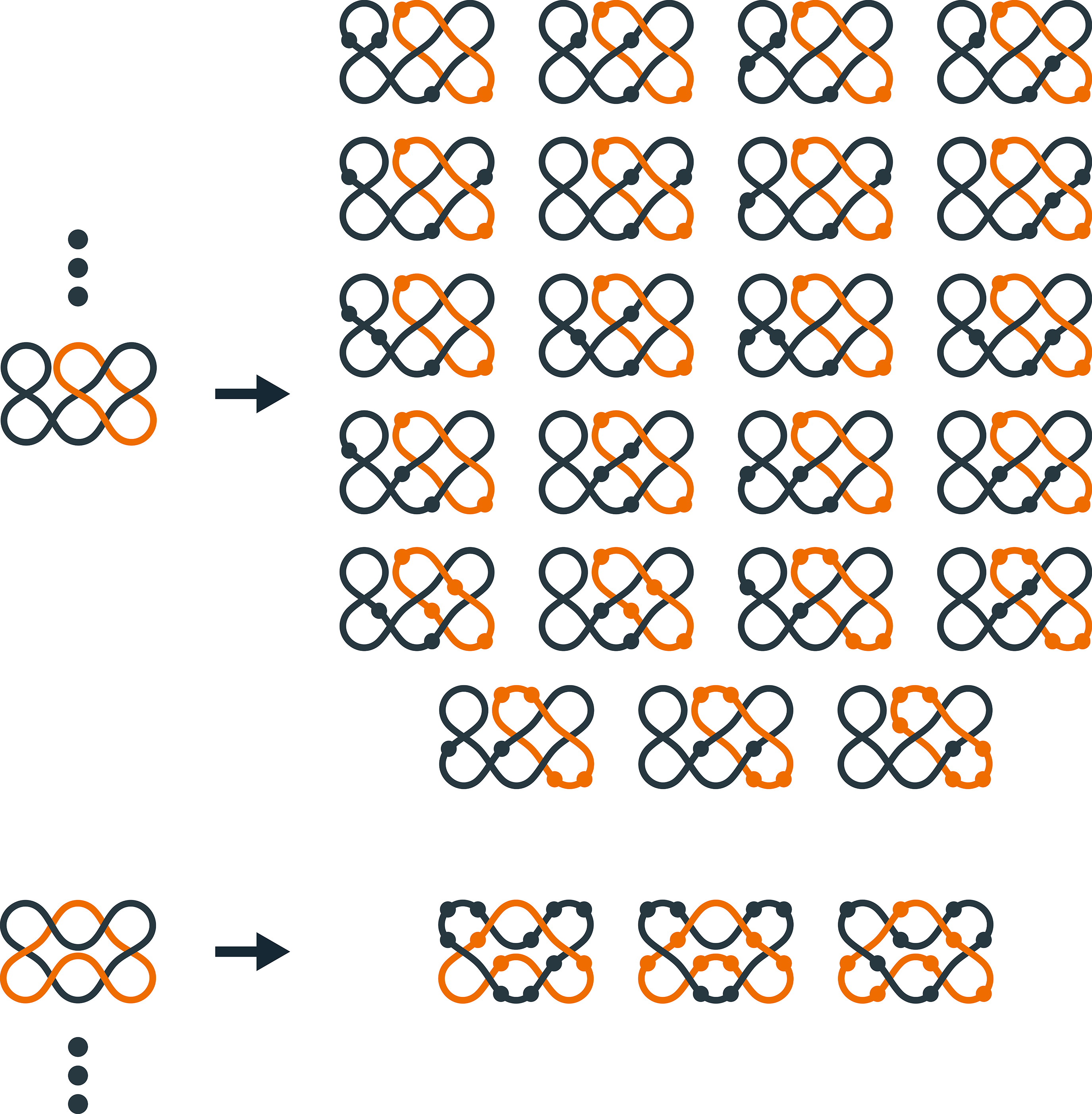
The inner workings of our novel algorithm
In this section, we will proceed to an explicit and concrete realisation of the four stages of our novel algorithm, as described in the previous section for an arbitrary maypole braiding machine with a configuration of
Enumeration of all horn gear arrangements
The goal of the first stage is to generate all unique configurations of the given set of horn gears Only the horn gears represented by dark circles are part of the respective horn gear configuration. (Left) Mapping of an example horn gear configuration of size 
We determine the unique configurations of the horn gears under reflection and rotation by considering all rotations and reflections of the horn gear configuration (cf. Figure 11) and identifying their minimal representation.
28
(Left) All four reflections relevant for a rectangular braiding machine. (Right) All eight reflections and rotations relevant for a square braiding machine.
We represent reflections (cf. Figure 12) and rotations (cf. Figure 13) by permutation matrices. The permutation matrix in the centre allows the structure on the left to be reflected on the y-axis. The resulting structure after reflection is shown on the right. The permutation matrix shown in the centre allows the structure on the left to be rotated counter-clockwise. The resulting structure after rotation is shown on the right.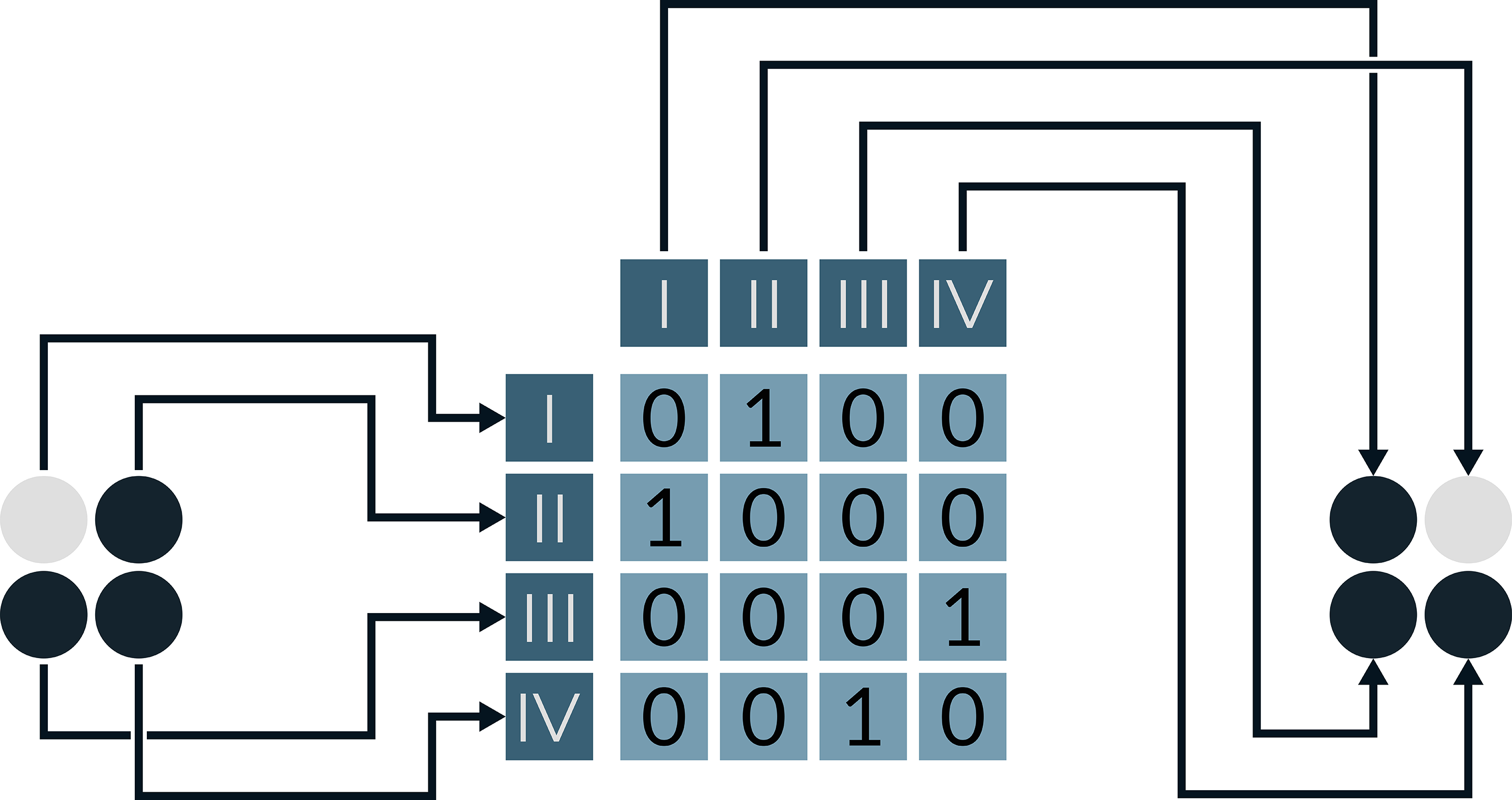
The bit-vector 
For each position On the left are the 8 different reflections and rotations of an example horn gear configuration. These are each assigned to a row on the right. Column by column, the minimum is given at the bottom right. The orange cells are larger than the column minimum. The corresponding permutation of the horn gear configuration is therefore larger than at least one of the others and does not need to be considered further.


Given the definition of the minimal representation of a bit vector with respect to a set of reflection and rotation permutations, we can generate the under reflection and rotation unique horn gear configurations as follows. To do this, we perform the following three steps until there are no more horn gears to remove.
A graph is said to be connected if each pair of vertices is joined by a path; otherwise, the graph is disconnected.
35
(Left) Connected graph. (Right) Disconnected graph.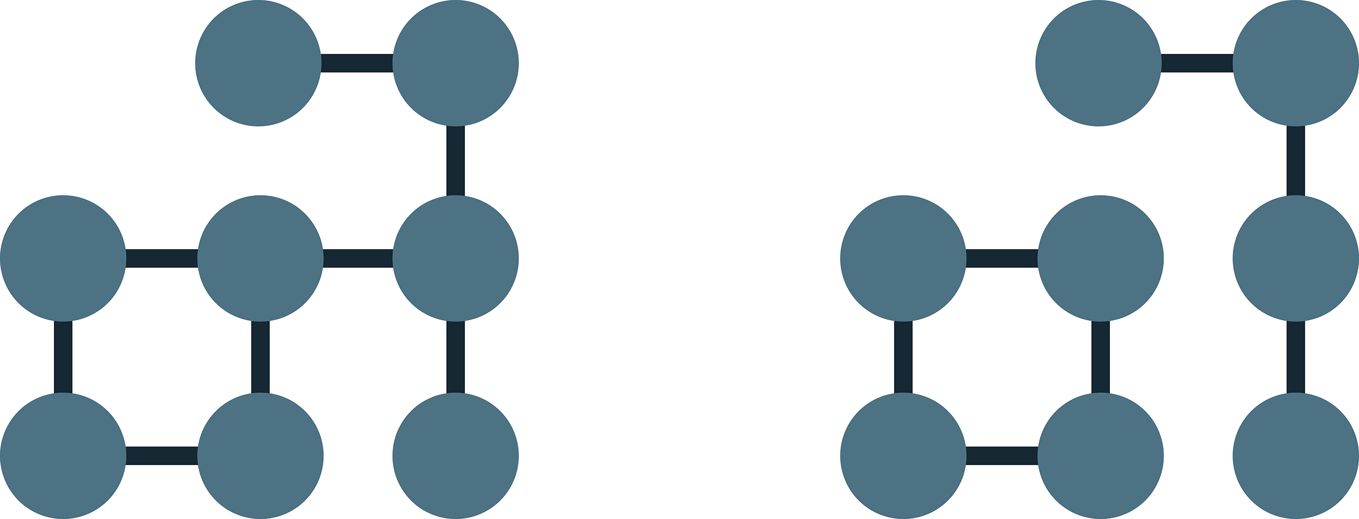
Figure 16 summarises how the algorithm performs its task. A graphical representation of the algorithm described in Section “Enumeration of all horn gear arrangements” for enumerating all under reflection and rotation unique, connected horn gear configurations. The horn gear configurations shown in the grey bar represent the minimal representation of the equivalent horn gear configurations grouped together from the previous step. The orange marked horn gear configurations are not connected and are discarded.
After executing this step of the algorithm, we obtain the set of all horn gear configurations
It should also be noted that the algorithm can be extended to take into account the results of previous calculations for smaller machines, thus speeding up the process by reliying on previously identified feasible solutions. To do this, an additional step (2.4) can be inserted to filter out the already evaluated horn gear arrangements only on the basis of their width and height.
Enumeration of all switch states
The objective of the second stage is to enumerate all switch states The representation of the switch state (left) presented as a bit vector (right). The large circles represent horn gears, while the light small circles represent switches in the “rotary” state. The dark small circles symbolise switches in the “transfer” state. The grey marked entries of the bit vector do not correspond to a horn gear or a switch. Their value is always 
The vector at position 
applies and a switch if

The following algorithm is executed for each horn gear configuration

with
and
A graphical representation of this algorithm is shown in Figure 18. A graphical representation of the algorithm described in Section “Enumeration of all switch states” for enumerating all switch states that are unique under reflection, and rotation, preserving the structure of the horn gear configuration. The switch states shown in the grey bars represent the minimal representation of the grouped equivalent switch states of the previous step. The switch states in orange are not connected and are discarded.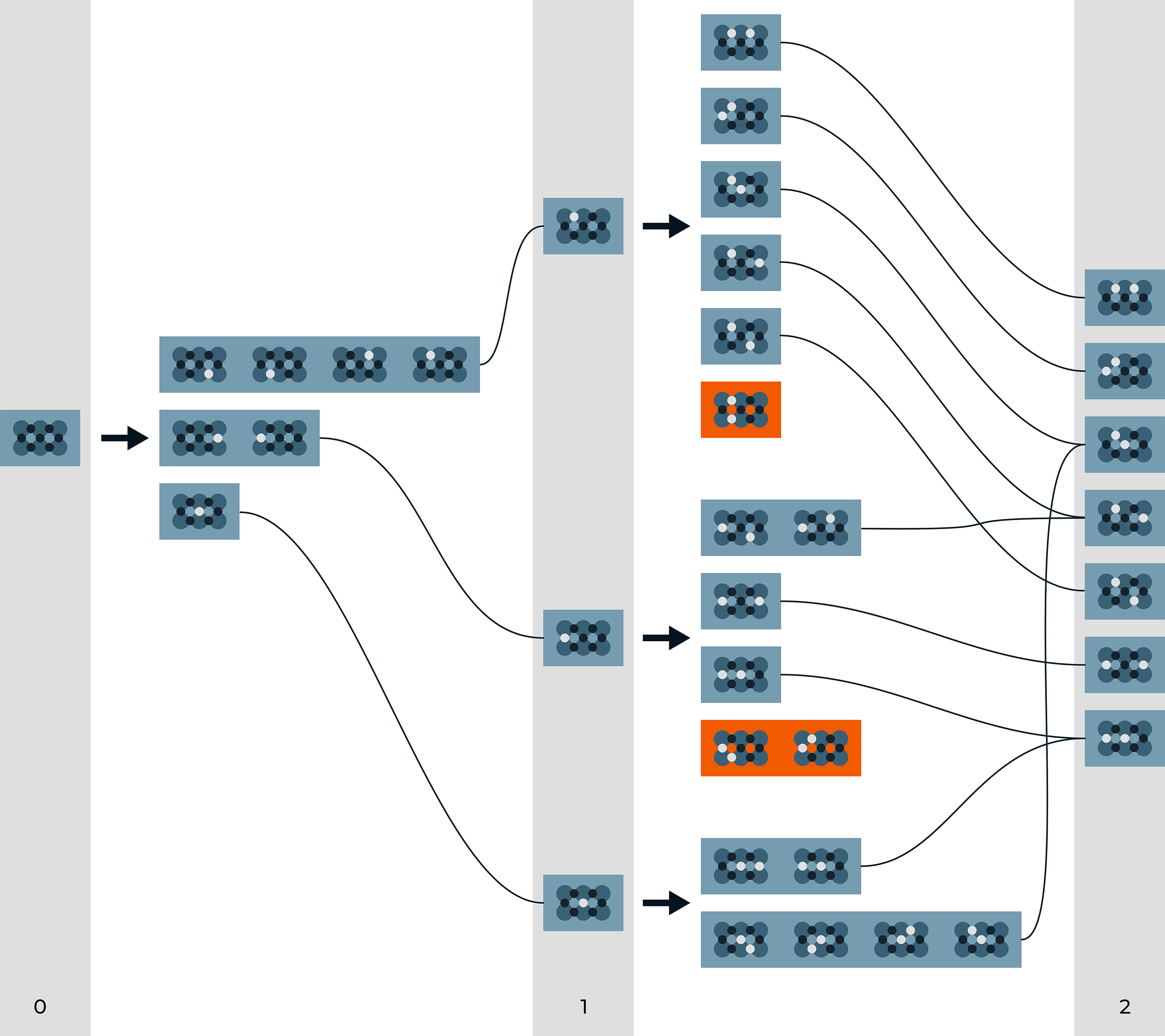
After carrying out the algorithm, we obtain the set of all switch states
Enumeration of all track layouts
The goal of the third stage is to calculate the track layouts Representation of the track layout (left) of a 
With


The horizontally oriented paths are described by the condition

The crossing paths between two horizontally adjacent horn gears are described with the condition

Accordingly, the bit vector characterises a path segment at position 
It is important to note that the switch positions and the two adjacent track curves cannot be active at the same time. At positions without slots or tracks, the bit vector contains the value
For each switch state


(Top) Three self-intersecting track layouts of different lengths with a single cycle. (Bottom) Three non-intersecting track layouts of different lengths with a single cycle.
(Top) Three track layouts of different lengths with several connected cycles. (Bottom) Three track layouts of different lengths with at least one unconnected cycle.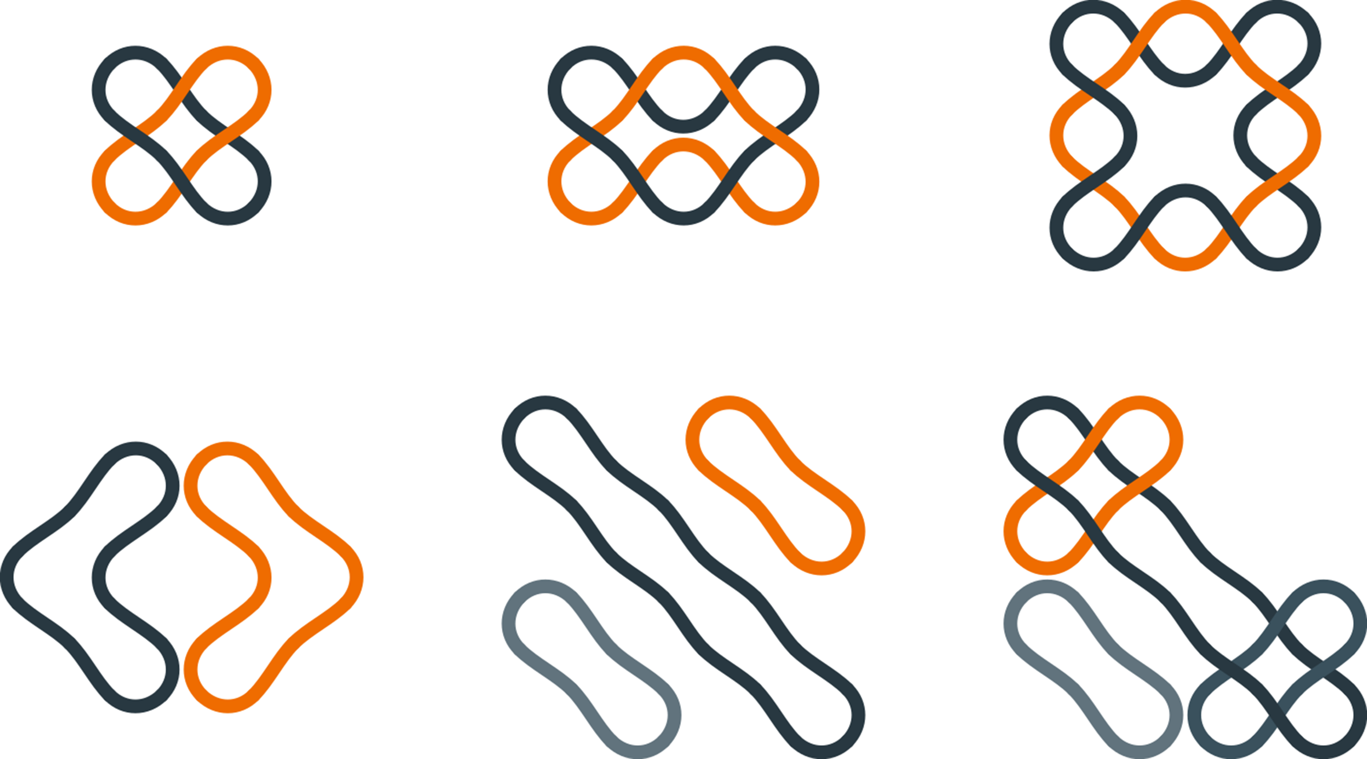
A graphical representation of this algorithm is shown in Figure 22. A graphical representation of the algorithm described in Section “Enumeration of all track layouts” for enumerating all track layouts, unique under reflection and rotation. The switch states shown in the grey bar are mapped to track layouts. For these, all combinations of cycles are enumerated. Then the minimal representation of these is saved. The track layouts with orange background have no self-intersections and are discarded.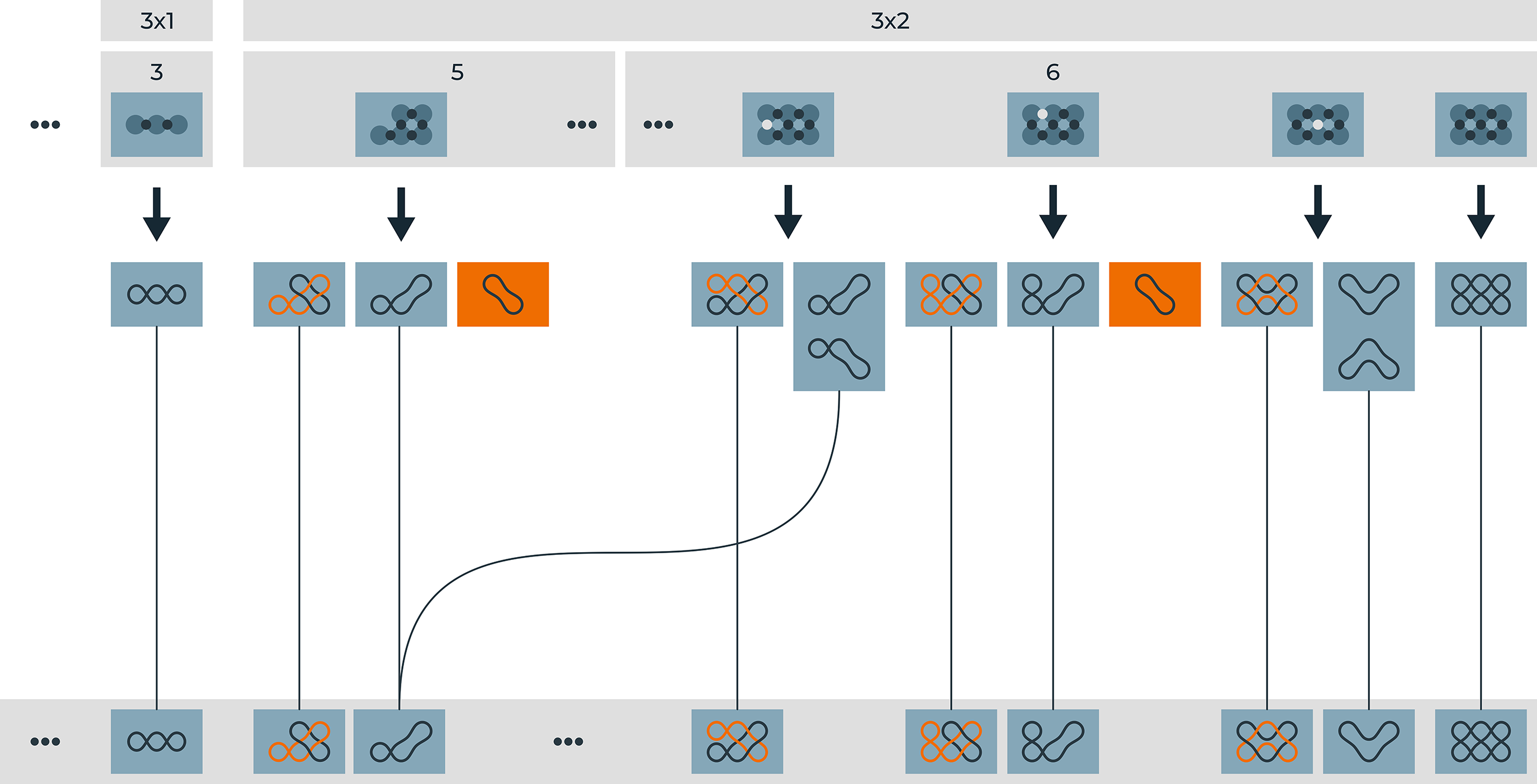
After carrying out the algorithm, we obtain the set of all track layouts
Enumeration of all carrier arrangements
The goal of the fourth and final step is to compute collision-free carrier arrangements
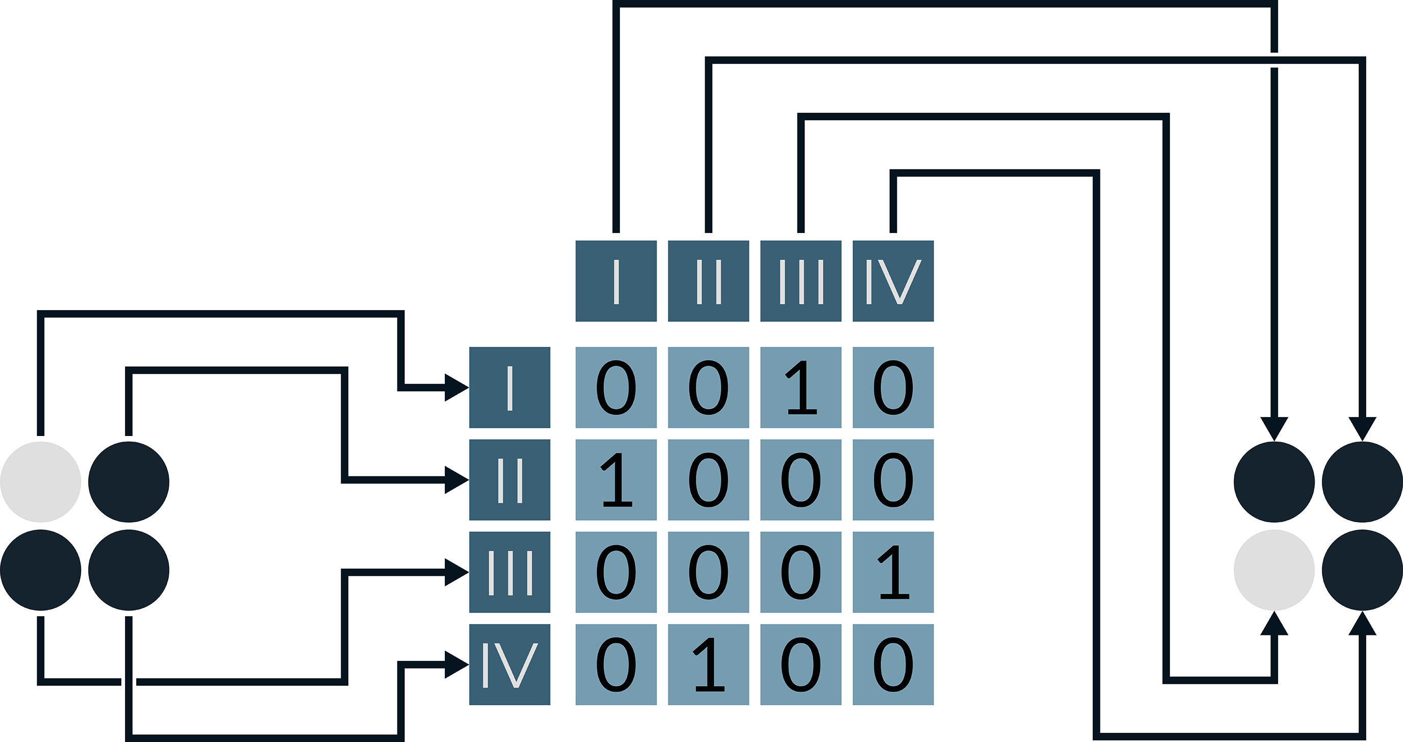
We take advantage of the fact that the horn gears are mechanically coupled and move synchronously. The movement of the carriers between fixed positions can therefore be modelled using a permutation matrix and treated in the same way as the reflection and rotation matrices.
We define the positions Representation of the carrier arrangement (left) as a bit vector (right). The entries of the bit vector are stacked according to the exploded view of the track layout (centre) for better understanding. The circles represent the slots in the horn gears. Dark arrows are part of the considered track layout and dark circles are horn gear slots occupied by carriers. The grey marked entries of the bit vector have no correspondence with horn gear slots or track segments. Their value is always 

To calculate the carrier arrangements, we use the set Diagram of the colliding horn gear slots (orange) as the braiding machine makes a complete revolution. Over the course of one revolution, the carriers at positions (VI,VII), (V,VIII), (I,IV), and (II,III) would collide with each other.

We represent the continuation of the carrier positions by turning the horn gear in 90° steps using the permutation matrix
For the braiding machine shown in Figure 25, the column-wise defined permutation scheme is given by Illustration of a braiding machine with two horn gears and a switch in the “transfer” state as a mathematical graph.

Based on the collision positions 
To do this, we determine the set
For each track layout
A graphical representation of this algorithm is shown in Figure 26. A graphical representation of the algorithm described in Section “Enumeration of all carrier arrangements” for enumerating all carrier arrangements, unique under reflection, rotation, and machine rotation advancement. For the track layout on the left, all collision-free carrier arrangements are generated. Carrier arrangements that do not occupy all cycles of the track layout are discarded (orange box). The remaining carrier arrangements are grouped and saved using their minimal representation.
After carrying out the algorithm, we obtain the set of all carrier arrangements
Conclusions and outlook on future work
In this paper, we describe an algorithm for enumerating all collision-free, carrier arrangements that are unique under reflection, rotation and machine rotation advancement. Our novel algorithm comprises four sequential stages, each of which can be efficiently executed in parallel on commodity hardware.
Calculation time in seconds on an AMD Ryzen 5 3600 6-core processor with 64 GB RAM.

Memory Usage (Residual set size) in Mebibyte (220 Byte = 1 MiB) on an AMD Ryzen 5 3600 6-core processor with 64 GB RAM.

The calculation time for a braiding machine with
Number of collision-free track layouts and carrier arrangements for braiding machines of different sizes that are unique under reflection and rotation.

Table 5 shows the number of track layouts and carrier arrangements we have identified for braiding machines of different sizes.
Comparison of the size of the search space and the size of the solution space for carrier arrangements and track layouts.
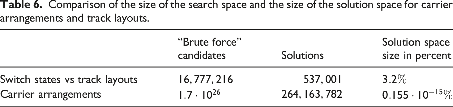
For braiding machines with
This article considers all carrier arrangements that are unique under reflection and rotation for braiding machines with up to Number of track layouts (y-axis) for braiding machines with different horn gear configuration dimensions (x-axis).
In this context, it is important to note that the number of track layouts increases in line with the number of horn gears. It can be observed that square horn gear arrangements contain more track layouts than those with rectangular horn gears.
No symmetry conditions are imposed on the track layouts. Consequently, both horizontally and vertically reflection-symmetric and asymmetric track layouts of the same dimensions are considered. In the existing literature, symmetric track layouts are more frequently investigated.10,19,21 Therefore, the solution set in Figure 28 has been restricted to vertically and horizontally symmetric track layouts only. Number of vertically and horizontally symmetrical track layouts (y-axis) for braiding machines with different horn gear arrangement dimensions (x-axis).
The 79 horizontally and vertically symmetric track layouts are shown in Figure 32. Our own representation of the 79 vertically and horizontally mirrored track layouts. These are grouped by machine size and number of cycles.
As expected, the number of layouts increases with the size of the machine. This is also true for the number of collision-free carrier arrangements, as Figure 29 clearly shows. Number of carrier arrangements (y-axis) for braiding machines with different horn gear configuration dimensions (x-axis). For each braiding machine size, the carrier arrangements are grouped according to the number of cycles of the track layouts (x-axis).
In Figure 30, we present the identified collision-free carrier arrangements, grouped by the number of carriers used. The number of collision-free carrier arrangements decreases with the addition of carriers. Exceptions to this rule are the even numbers of carriers except 6, 18 and 22 carriers. For these, there are more collision-free carrier arrangements than for their respective predecessors. We suspect that this phenomenon has its origin in special symmetry properties. Number of carrier arrangements (y-axis) with different numbers of carriers (x-axis).
We compared the braids described in the literature for right-angled maypole braiding machines with our own findings. Our algorithm identified the square (pp. 285–286), tubular (pp. 303–304) and Y-like profile braids (p. 305) described in Chapter 12 of “Braiding Technology for Textilesˮ. 19
In addition, we used brute force to calculate the carrier arrangements for a random sample of track layouts of up to 3 × 3 horn gears and compared them with the solution set identified by our novel algorithm. As there were no deviations, we assume that the algorithm and its implementation are correct.
At the time of publication of this paper, a browser-based, interactively searchable database of our results for braiding machines up to the size of
Our novel hierarchical approach to enumerating all collision-free carrier arrangements that are unique under reflection, rotation and machine rotation advancement represents a significant advance in the field of data-driven search for novel braids. This approach has the potential to contribute to new breakthroughs, particularly in the area of tissue engineering research, where braided scaffolds are favoured for their properties. 31
To build on this work, we identify the following scientific questions as particularly relevant. • The carrier arrangements that we have enumerated are collision-free. However, this does not necessarily result in the generation of a braid, for example, if the threads are only wound around each other (cf. Figure 31). In this context, our objective is to develop a model that will enable us to quantify the structural braid properties. This can then be used to filter out invalid braids. Furthermore, we hope that such a model will enable us to search for braids with certain properties. • The carrier arrangements that have been identified are geometrically unique under reflection, rotation, and machine rotation advancement. However, this does not necessarily apply to the structure of the resulting braids. With the help of Artin-Generators,32,33 the aim is to identify braids that are structurally identical. If such braids exist, it may be possible to identify physical braid properties as a function of the track layout. • The various track layouts can be converted into one another by means of manipulation of the switch states. Furthermore, a number of collision-free carrier configurations for the track layouts have been identified. It is of interest to ascertain whether there are “neighbouring” track layouts with carrier configurations that can be transformed into one another by changing the switch states and rotating the horn gears. On the assumption that such “neighbours” exist, our intention is to identify a neighbourhood network that will facilitate the creation of braids with changes in the macrostructure by navigating the neighbourhood graph-network. • The method presented here is specific to braiding machines with rectangular horn gear configurations. It would be of interest to adapt the illustrated process for circular braiding machines and their distinctive symmetrical properties. • Furthermore, it would be advantageous to extend the method to encompass rule-based constraints. These could be employed to quantify problem-oriented limitations on horn gear configurations, switch states, track layouts, or carrier arrangements, thereby enabling the enumeration of the solution space for machines with larger dimensions. • Currently, it is not possible to estimate the calculation time for a Maypole braiding machine of size m × n in advance. To estimate the feasibility of calculations for braiding machines with more than 4 × 4 horn gears under assumed boundary conditions, it would be advantageous to have a formula for estimating the size of the solution space. Three different carrier arrangements, none of which result in a valid braid.

Source transparency
Following the recommendation of Severin and Low, 34 only sources that were not classified as an article in a predatory journal were included in this publication.
Footnotes
Author contributions
Jan Elmar Krauskopf: Conceptualization, Methodology, Formal analysis, Software, Validation, Writing and Visualization.
Andreas Rauh: Writing - Review & Editing.
Andreas Hein: Supervision, Writing - Review & Editing.
Funding
The authors received no financial support for the research, authorship, and/or publication of this article.
Declaration of conflicting interest
The authors declared no potential conflicts of interest with respect to the research, authorship, and/or publication of this article.
Declaration of generative AI and AI-assisted technologies in the writing process
During the preparation of this work the author used DeepL Translate and Deepl Write in order to translate the draft version written in German into English. After using these services, the author reviewed and edited the content as needed and takes full responsibility for the content of the publication.