
Abstract
The arc generated by breaking the main circuit exacerbates the ablation of the contact, which affects the life of the contactor seriously. By controlling the breaking time of the contactor and making contact break in the optimum time zone are the effective ways to weaken the arc. In this article, the contact movement characteristic is concerned directly in order to control the contact breaking time. A back-to-back double-E alternating current contactor is proposed, and its structural parameters are optimized by particle swarm optimization algorithm. The mathematical model of circuit and magnetic is established. A closed-loop control system based on velocity feedback is proposed. The simulation results show that the designed contactor and the proposed control method are correct, and the actual velocity curve of the contact is consistent with the planned motion curve. It can realize zero-crossing breaking of the main circuit to achieve the effect of no-arc breaking.
Keywords
Introduction
In recent years, China’s power system development has undergone unprecedented new changes. This change is reflected in the continuous expansion of the proportion of new energy power resources, and the operational accuracy and controllability are more required. 1 The main problem of renewable energy represented by wind power generation is the complexity of its control. At present, the large-scale off-network has been mainly concerned, which is caused by its internal or external factors. With the increase in peak modulation position of wind turbines, wind turbines are required to frequently input or exit in accordance with dispatching orders. At present, AC690V contactors are often used in wind turbines. In order to avoid false and refuse shutdown of wind turbines, higher requirements on the service life and reliability of contactors have been proposed. 2
The alternating current (AC) contactor is used to break the AC load circuit. Due to the frequent operation, the contactor must have a long enough operating life to ensure a certain service life, and the electrical life of the contactor is the key to affect the operating life of the contactor. The main factor affecting the electrical life of the contactor is the ablation of the contact by the arc when the contactor breaks the main circuit, that is, the electrical wear of the contact. If the precise control of the contact-breaking process can be achieved, the electrical wear of contacts can be reduced, and the electrical life of the contactor can be increased by nearly 20 times. In addition, the no-arc breaking can also reduce the pollution of harmful metal vapors to the air, reduce the requirements on the arc extinguishing device, and improve the actual making and breaking capability of the contactor. The social and economic benefits brought by the above are quite large.
At present, some research results have been obtained on the no-arc breaking control method of AC contactors. In the work by Zhang, 3 a combined no-arc contactor is proposed, which relies on a thyristor as a bridge to realize no-arc breaking of two contacted contactors in both its on and off states. The method uses two separate contactors and one thyristor, increasing the cost of the device. In the works by Zhihong and Peiming,4,5 a zero-current breaking method for three-phase neutral ungrounded inductive load systems is proposed. The optimal region for zero-current breaking is proposed, 6 which is 0.3–0.4 ms before the first phase current zero crossing. By storing and adjusting the breaking time, an adaptive adjustment method is adopted in order to make the breaking time falls in the optimal region. However, the above literature does not propose how to achieve precise control of the contact breaking time.
This article pays close attention to the contact motion characteristics of the contactor. A back-to-back double E-type AC contactor is proposed for closed-loop control of the contact motion characteristics. By establishing a reasonable speed planning curve, the contacts can be accurately separated in the optimal time zone, and the optimal breaking time is the zero crossing of main circuit current phase. In this article, the mathematical model of AC contactor is established, the calculation method of relevant parameters is defined, the speed feedback closed-loop control system is constructed, and the dynamic response characteristics of contactor are analyzed. The simulation results show that the designed contactor model and the proposed control method are correct.
Back-to-back double E-type contactor structure and working principle
Different from the traditional contactor structure, the contactor electromagnetic mechanism proposed in this article is composed of two E-shaped electromagnets arranged back to back, and its structure is shown in Figure 1.

Back-to-back double-E AC contactor structure.
The contactor shown in Figure 1 is in an open state, and the electromagnet 1 is strictly isolated from the electromagnet 2. The armatures of the two electromagnets are connected rigidly and move synchronously. A detection and control circuit is arranged in the bottom area of the contactor for mounting the speed sensor, which is used to detect the armature speed signal. The speed signal is send to the central processing unit, and a signal from the processor which can drive the electromagnet.
During the contactor-breaking process, the electromagnet 2 is energized to provide suction for the armature 2, and the anti-force spring will also provide upward thrust for the armature, so that the armature accelerates in the direction of the over-travel. By collecting the speed of the armature, the coil current and suction of the electromagnet 2 can be changed in real time. Thereby, it can ensure that the actual movement speed of the armature can track the reference speed. When the contact passes the over-travel distance and realizes the breaking, the electromagnet 1 is energized when the arc is substantially disappeared, so that the armature 1 is decelerated. As with the acceleration process, the coil current of the electromagnet 1 can also be changed by the speed signal feedback, thereby the suction force of the electromagnet 1 can be changed in real time. When the contact passes the distance of the opening distance, the contact speed is close to zero in order to reduce the collision between the moving iron core and the bracket.
Therefore, in essence, the back-to-back double E-shaped AC contactor achieves the fundamental purpose of controlling the contact motion by coordinating the suction and anti-force of the two electromagnets.
Back-to-back double E-type contactor mathematical model
Anti-force system model
In this article, the combined contactor adopts the contact system of CJX1-63 type, and its rated voltage and current are 220 V and 63 A, respectively. The comparison of design parameters with the original parameters is shown in Table 1.
Anti-force characteristic parameter.

The reaction characteristics of the original and the designed system are shown in Figure 2. The reaction characteristic curve is a sectional curve. After the contactor coil is cut off, the moving contact and the static contact are not completely separated within the over-travel; at this time, the system anti-force is provided by the anti-force spring and the contact spring together. When the contact has gone through the over-travel, the contact spring will no longer provide the anti-force, and only the anti-force spring will provide the anti-force within the following open range.

Anti-force characteristic curve.
Considering that the mass of the movable parts of the new system is reduced, the release spring pressure is reduced by 1/3 compared with the original system. For arc-free breaking, the contact distance is reduced from 5.5 to 4.0 mm.
Mathematical model of electromagnetic suction
The E-type electromagnet has symmetry and folds along its midline, as shown in Figure 3.

Electromagnet structure model.
Electromagnetic suction force F can be mathematically expressed as

where B is the magnetic induction through the air gap, S is the cross-sectional area of the iron core passing through the air gap, μ0 is the magnetic permeability of the air, and F varies with the change in the magnetic induction B through the air gap. As the magnetic induction intensity increases with the increase in excitation current, the relationship between electromagnetic attraction and excitation current is positive correlation.
The magnetic flux ϕ passing through the air gap has the following relationship with the magnetic induction B as shown in equation (2)

According to equations (1) and (2), F can be obtained as

F depends on the magnetic flux ϕ passing through the air gap. Therefore, the magnetic circuit should be analyzed to calculate the magnetic flux value. The equivalent magnetic circuit of the electromagnet is shown in Figure 4.
Electromagnet equivalent circuit.
The loop equation is as follows
where ϕA is the magnetic flux through the air gap, ϕB is the core flux at the excitation coil, H is the magnetic field intensity of the corresponding part, GL is the leakage flux between the iron core columns, and Gδ(x) is the air gap magnetic conductance.
Equation (4) can be transformed into equation (5)

Combining equations (3) and (5), the electromagnetic suction F depends on the magnetic flux ϕA flowing through the air gap. Without considering the saturation of the ferromagnetic material, the magnetic flux is different from the magnetic intensity by a proportional coefficient. If the effect of the air gap is not considered, the magnetic flux in equation (5) will be very easy to obtain.
Due to the presence of an air gap, the magnetic flux flowing through the air gap will be affected by the air gap permeability. In general, the air gap magnetic conductance and the air gap distance are inversely proportional. In actual design, it is impossible to achieve full contact when the contact closure and a certain gap will be left. On one hand, this is to prevent the nonlinear problem caused by the small air gap. On the other hand, it is also limited by the manufacturing process. This article sets the contact distance when the electromagnet is closed with only 1% of the electromagnet remaining. Therefore, the air gap permeability can be expressed as

where μ0 is the magnetic permeability of air, δk is the contact distance when the electromagnet is released, and x is the real-time displacement of the electromagnet closing process.
The edge diffusion flux should also be considered during design, so equation (6) should be revised. It is determined that the edge diffusion magnetic conductance is 0.5 times of the uniform magnetic conductance in the released state and 0 in the closed state. It is assumed that the air gap magnetic conductance changes linearly during the closing process of the electromagnet. The relationship between the magnetic flux flowing through the air gap and the armature displacement can be obtained as follows

Circuit mathematical model
The Kirchhoff voltage equation of excitation coil can be expressed as

The control circuit parameters include inductance and resistance. The resistance is generally only related to the ambient temperature. When the measuring environment is 15°C, the resistance of the excitation coil is 50 Ω. The coil is put into the incubator, and the coil resistance can be measured at different temperatures using infrared thermometer. The test results are shown in Table 2.
Coil resistance at different temperatures.
However, the inductance is related to the movement position of the electromagnet armature. In order to control the moving parts of the contactor effectively, the inductance value must be calculated in real time. In the works by Espinosa et al.,7,8 the application of current increment to determine the inductance value is proposed, and the current value of 0.5 and 0.25 s is selected before and after the sampling time to calculate. This method effectively saves the speed and position detection device, but it is not accurate to summarize the exact correspondence between the inductance value and the armature motion process. Based on the displacement and velocity control of the moving part of the contactor, it is extremely necessary to find the relationship between inductance and motion displacement in this article. The inductance of the control circuit can be expressed as

Equation (9) is transformed to obtain equation (10)

In equation (10), GL is related to the size of the electromagnet, which can be obtained by consulting relevant manual. Gδ(x) is a linear function of the armature displacement, so the dynamic real-time value of the control circuit inductance is obtained correspondingly.
Moving part model
The equation of motion of the electromagnetic system can be expressed as

where F is the resultant force of the moving armature, FX is the electromagnetic attraction, Ff is the anti-force, m is the total mass of the moving part, and x is the armature displacement.
Contactor structure optimization design
In order to reduce the collision energy and iron core material, a set of relatively optimized contactor structure parameters can be obtained based on the optimal search function of particle swarm optimization algorithm.
Particle swarm optimization algorithm
In general, the parameters obtained by the conventional design cannot achieve the optimal effect, and it needs to be repeatedly iterated to verify whether the optimal index can be achieved. As a global search optimization algorithm, particle swarm optimization provides a good way.
The basic idea of particle swarm optimization is that every solution of optimization problem is called a particle. A fitness function is defined to measure the superiority of each particle solution. Each particle swims in groups according to its own and other particles “flight experience,” so as to achieve the purpose of searching the optimal solution from the whole space. 9
The basic steps of the algorithm are as follows:
Set the initial parameters of the algorithm according to the index requirements, divide the solution area, and set the number of iterations.
Set a set of variables to be optimized according to the preliminary design method, which is called particle swarm.
Apply particle swarm to solve. If the requirements of the objective function are met, save the particle, if not, generate new particles for recalculation.
When the requirements of the objective function or the number of iterations are met, the calculation is terminated.
Optimization variables and objective function
The optimized variables are the total length of the iron core, the height of the iron core column, the height of the yoke, and the length of the middle iron core.
The design of the direct acting contactor aims at faster closing time, smaller collision speed, and smaller core mass. 10 The objective function considering these three terms is
where T(x) and T0 are the real-time calculation values and initial values of closing time, respectively; V(x) and V0 are the real-time calculation values and initial values of collision speed, respectively, reflecting the magnitude of collision energy; m(x) and M0 are the real-time calculation values and initial values of core mass, respectively, reflecting the production cost; and α, β, and γ are the weights of the three, depending on the concerns of designers.
Constraint condition
In the process of optimization, there may be infinite possibilities, which need to be limited by setting constraints according to the actual situation, including the size constraints and mutual constraints of the mechanism, the holding force and anti-force must meet the reliability coefficient, the speed of the closing process must be greater than zero, etc.
Optimization results
The dynamic optimization design of cjx1-63 AC contactor is carried out using particle swarm optimization algorithm, and the optimization results are shown in Table 3.
Parameter optimization result.

Closed-loop control of contact motion characteristics
Contact-breaking process
The contact system is connected to the upper part of the electromagnet 1 and moves synchronously with the electromagnet. The schematic diagram of the contact-breaking process is shown in Figure 5. When the moving contact and the stationary contact are closed, the two contacts are usually in a pressed state in order to close completely. When the moving contact moves a distance of the over-travel, the extrusion of the two contacts disappears, and the two contacts begin to separate. The speed of moving contact decelerates to zero after passing through the air gap distance and the contact-breaking process is completed.

Contact-breaking process diagram.
Speed closed-loop control strategy
In order to realize the control of the breaking moment of the moving and static contact, making armature at an ideal speed in the over-travel is the fundamental way to solve the problem. It is desirable to separate the moving and static contacts at the optimum breaking time, so that the arc at the time of separation is minimized.
Some scholars have carried out research on intelligent contactor voltage11,12 and current feedback control 13 to achieve less bounce of contact closure, indicating that feedback control is feasible in contactor control. In this article, a speed closed-loop control system is designed based on the mathematical model of each part of the electromagnet. The power source of the speed closed-loop control system is an electromagnet 1 and an electromagnet 2, respectively, which control the speed by controlling the suction and anti-force force of the two magnets on the moving parts.
A block diagram of the system based on speed control is shown in Figure 6.

System diagram based on speed control.
The input quantity in the control system is the desired motion speed, and the output quantity is the actual motion speed. The mathematical model of the control circuit, electromagnetic force calculation, and motion equation in the system has been obtained. The speed is subjected to negative feedback processing such that the speed error is corrected by the proportional integral (PI) regulator to obtain a reference value of the input voltage Uref of the control circuit, as shown in equation (13)

The proportional coefficient is to make the output signal and the input signal deviation proportional, so that the output signal can quickly respond to the input signal. The integral coefficient is cumulative, and its output signal is directly proportional to the integral of the deviation value of the input signal. Therefore, the coefficient can eliminate the steady-state error of the system.
When the actual motion speed and the given motion speed produce an error, the proportional link can make the response speed track quickly, and the integral link eliminates the tracking static error and improves the accuracy.14,15
In order to verify the closed-loop control system designed in this article, the response of the system at a given step speed is studied first. The simulation model is built in the MATLAB/Simulink environment, as shown in Figure 7.

Closed-loop step simulation model.
The simulation model includes a circuit model, an electromagnetic suction calculation model, an anti-force model, and a motion model. Input a given speed, the output speed is fed back to the input, controlled by the PI regulator. The necessary motion process limit control and saturation control modules are added to the system.
Figure 8 shows the contact velocity tracking of a given step signal in a closed-loop control system of a contactor, which is built in MATLAB/Simulink environment. Due to the presence of the inductor, the tracking speed is slow. The tracking time is about 0.2 s, while the contact speed is from 0 to 20 mm/s. In this article, the control method of the given follow-up signal is adopted, because the contact-breaking process itself needs an acceleration process. It is obviously impractical for the moving contact to suddenly reach a given large step signal. Therefore, adopting a follow-up speed reference curve for improving the accuracy of control is a matter of great practical significance.

Simulation results of a given step velocity signal.
In order to verify the contact motion control characteristics, the input curve is given on the simulation platform. The input curve is shown as constant deceleration after constant acceleration, which is reasonable actually. The contact moves in a constant acceleration within 0–0.2 s at a given planned speed up to 25 mm/s and then moves in a constant deceleration. The simulation results are shown in Figure 9. Compared with no closed-loop control, the moving speed of the moving iron core can be controlled, and the contact can be disconnected at the zero crossing point of the main circuit.

Simulation results of contact speed.
The simulation waveform shows that the actual speed signal is very consistent with the reference speed within 0–0.3 s, indicating that the speed control performance is ideal. A certain deviation occurs after 0.3 s, because the contactor parameters cannot be given in response to the high slope speed. However, this does not hinder the purpose of the contactor speed control. As long as the slope of the given speed follow-up signal is reasonably determined, a reasonable contact motion curve is planned, and the moving speed of the contact can be precisely controlled. So the breaking time can also be determined.
Selection of breaking time
Through motion planning, the contact breaking moment is exactly an optimal breaking moment (△T) before current zero crossing, as shown in Figure 10. By planning and controlling the contact movement, it can go through the over-travel within the specified time, and contact can break at a precise ideal time.
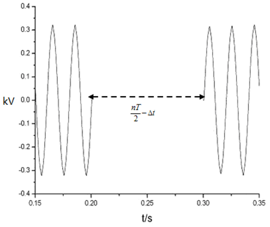
Breaking time schematic.
The optimal region of zero-current breaking is usually 0.3–0.4 ms before current crossing zero. This time mainly depends on the action of the electromagnetic mechanism and has certain uncertainty. The hysteresis of the electromagnetic mechanism will make the breaking time fall outside the optimal region, which lead to break failure.
Adaptive control is to modify the delay time of breaking command adaptively, which is the delay time when the contactor receives the breaking command sent by the software. If the breaking fails, the arc is not extinguished. At this time, the delay time is modified and the cycle is repeated until the breaking time falls in the optimal breaking area.
Simulation result analysis
According to the foregoing discussion, a reasonable contact motion curve is planned to control the contactor breaking time. An ideal breaking moment is determined in the over-travel range. When the contactor moves outside the over-travel, the arc can be suppressed and the collision between the moving iron core and the bracket can be avoided. In order to achieve no-arc breaking, the focus is on the movement of the contacts in the over-travel.
In order to verify the correctness of the proposed method, the dynamic and static contacts are designed to break at the moment of current zero crossing. The over-travel is fixed at 2 mm, and the contact is uniformly accelerated in the over-travel, and the calculated acceleration is 156.25 mm/s2. The reference motion curve input simulation model according to the relevant data. The simulation results are shown in Figure 11. The results show that the speed of the contact-breaking process is consistent with the reference speed. After 0.16 s (eight cycles), the contact goes to the end and break at the zero crossing moment. The contact begins to slow down when 0.04 s after the breaking. When the contact passes the distance of the opening distance, the contact’s speed is close to zero, so the collision between the moving iron core and the bracket is avoided.

Simulation results of breaking time control.
Conclusion
The back-to-back double E-type AC contactor structure is proposed. Through the cooperation of suction and anti-force, the controllable speed of the contact can be achieved.
The mathematical model of the contactor circuit and the magnetic circuit is established, and the solution method of some key parameters is clarified. The structural parameters are optimized by particle swarm optimization algorithm.
The closed-loop control system of contact motion characteristics is designed. The simulation results show that the actual velocity curve of the contact motion is consistent with the reference curve, which can achieve precise control of the contact breaking time.
Although the speed closed-loop control system adds the auxiliary control structure, the dynamic characteristics of the contactor have been improved obviously.
Footnotes
Handling Editor: Xianfu Chen
Declaration of conflicting interests
The author(s) declared the following potential conflicts of interest with respect to the research, authorship, and/or publication of this article: All authors have seen the article and approved it to submit to your journal. The authors confirm that the content of the article has not been published or submitted for publication elsewhere.
Funding
The author(s) disclosed receipt of the following financial support for the research, authorship, and/or publication of this article: The authors gratefully acknowledge the support from National Natural Science Foundation of China (Serial No. 51177105).