
Abstract
Since the working situation of photovoltaic modules cannot be tracked in the real time and defective components cannot be located and controlled specifically, a remote monitoring system of photovoltaic modules based on wireless sensor networks is designed to improve the management efficiency of photovoltaic power plants. The monitoring data (current, voltage, and illumination, etc.) of photovoltaic modules are collected by the wireless sensor network nodes in real time, and then, there are orderly transmitted to the coordinator and server by the ZigBee communication protocol with the time synchronization algorithm. Time synchronization algorithm based on Gaussian delay model performs best in synchronization accuracy and energy-efficient reference broadcast synchronization algorithm is the most advantageous in synchronization energy consumption. Adaptive energy–efficient reference broadcasting synchronization algorithm is proposed with a balance between energy consumption and accuracy, which is applicable to large networks and thus conducive to the application of wireless sensor network in large-scale photovoltaic module monitoring. With the analysis and processing of the received data, the situation of the photovoltaic modules can be accordingly judged and thus the information management of photovoltaic power plant can be realized. For a photovoltaic power plant with a total power output of 100 kW and with 400 photovoltaic modules, experimental results show that the overall efficiency of the photovoltaic power plant can be increased by a wide margin.
Keywords
Introduction
As a kind of renewable energy which can help solve the energy crisis, solar energy has been widely used and popularized. With the spread of distributed photovoltaic (PV) power plants, scholars have carried out extensive research on the power generation efficiency of the PV power plant. However, many research works have been carried out on the system level.1–3 It is noteworthy that PV modules, as the direct basic unit of PV conversion, needs to research in terms of conversion efficiency of a single-PV module in the changeable environment.
In this sense, a remote monitoring system of PV modules has been designed to collect the operational parameters and monitor the situation of the PV power plants. Meanwhile, since the real-time requirements of the remote monitoring system should be taken into account, the time synchronization has been researched when ZigBee communication protocol is designed.4–6 In recent years, the research on wireless sensor network (WSN) time synchronization technology mainly focuses on improving the synchronization accuracy and reducing the synchronization energy consumption. J Elson et al. 7 proposed a time synchronization protocol for WSN–reference broadcast synchronization (RBS) protocol, which is a typical switched non-feedback time synchronization mechanism. It estimates the time stamp recorded when the adjacent nodes exchange reference broadcast information frequently and obtains the phase and frequency offset of the clock.8,9 Y Wang et al. proposed an improvement on RBS algorithm: energy-efficient reference broadcast synchronization (ERBS). The remarkable feature of the algorithm is that it only calculates the average phase deviation for two non-adjacent receiving nodes. The algorithm reduces the energy consumption, while ensuring the synchronization accuracy better than RBS. 10 X Guan et al. proposed low-power clustering-based time synchronization (LCTS). This algorithm combines one-way broadcast synchronization and two-way pairwise synchronization, which can reduce the synchronization energy consumption while ensuring the synchronization accuracy. However, the number and scale of WSN nodes are not fully considered. 11 Djenouri puts forward the relative reference receiver/receiver time synchronization (R4-Syn). It is an improved algorithm based on RBS. The main problem is that the network topology is complex and it is difficult to be applied to large-scale PV module monitoring. 12 Michael et al. proposed consensus clock synchronization (CCS). After constructing consensus clock and having phase compensation and frequency compensation, the CCS algorithm has good scalability and is suitable for large-scale PV module monitoring. But the biggest problem is the high cost of synchronous message, which is not conducive to improving the integrated efficiency of PV system. 13 The recursive time-sync protocol (RTSP) is proposed by Akhlaq et al. RTSP is an improved timing-sync protocol for sensor network (TPSN). The synchronized node can achieve time synchronization with beacon node using multi-hop mode. It has strong time synchronization flexibility and low synchronization energy consumption, so it is possible to apply it for large-scale PV module monitoring. 14 A WSN time synchronization algorithm based on Gauss delay model (TSP-GDM) is proposed by X Sun et al. Local switching and sharing of time stamps among local nodes are realized by wireless broadcast characteristics of nodes. Clock deviation estimation of intra-layer nodes based on Gauss delay model is applied to solve the problem of clock deviation estimation. 15
In this article, adaptive energy–efficient reference broadcasting synchronization (AERBS) algorithm is adopted. With the analysis and processing of the received data, the situation of the PV modules can accordingly be judged, the information management of PV power plants can be realized, 16 and thus, the integrated generation efficiency of PV power plants can be improved. The system has no obvious drawbacks except that it may increase the appropriate cost and stability needs further verification.
Composition of remote monitoring system of PV modules
The remote monitoring system of PV modules can collect data such as real-time voltage, real-time current, and temperature through the WSN node. Then, the received data will be packed and transmitted to the WSN coordinator through the ZigBee network. Next, coordinator will transmit the data packet to the backstage server through the recommended standard (RS)-232 serial port and those received data will be analyzed and handled by the server, offering the data support to the running and maintenance of the PV modules. System structure is shown in Figure 1. The system design mainly considers the practical challenges of generating capacity measurement and fault monitoring in PV power station. So designing the above-mentioned system structure will be further discussed later.
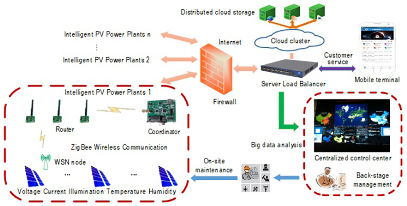
System structure diagram.
Design of hardware circuit of the system
The hardware circuit of the system includes the node, router, and coordinator. WSN node collects data of voltage, current, illumination, temperature, and humidity of every PV module in real time and then sends the data to router through the radio frequency module. As the relay of data transmission, the router sends the received data from the wireless sensor node to the coordinator which in turn transmits the data packet to the backstage server through the RS232 serial port.
We choose CC2530 chip as the processor. This chip works well with the solution of system-on-chip (SoC) in ZigBee protocol, integrating the 2.4-GHz wireless transceiver module with 8051 microcontroller (MCU) kernel in conformity with Institute of Electrical and Electronics Engineers (IEEE) 802.15.4 standard. In this way, a multipoint fast hoc network is built with a high data transmission rate of a CC2530. The availability and reliability of short distance communication can be guaranteed. Given its high integration and rich hardware resources, the chip requires only a couple of external components and its stable performance and low consumption.
Circuit design of WSN nodes
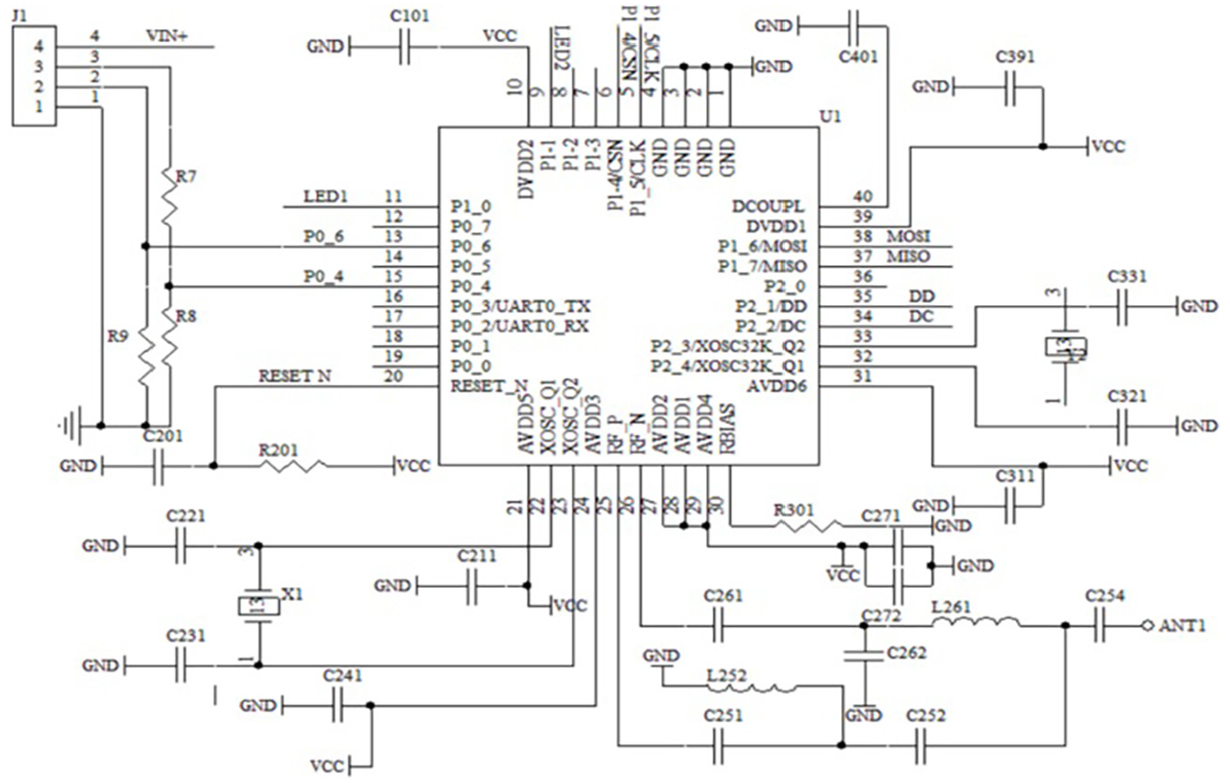
WSN node needs to accomplish the collection and transmission of data. The node circuit is composed of a master chip CC2530, a current transformer, a voltage sampling circuit, a temperature sampling circuit, and so on.
The sampling circuit collects data such as current, voltage, illumination, and temperature. These data provide the basis for the situation diagnosis of PV modules. After this, the CC2530 will complete preliminary processing and wireless transmission of sampling data. Circuit diagram of WSN node is shown in Figure 2.
Schematic diagram of node.
Design of router circuit
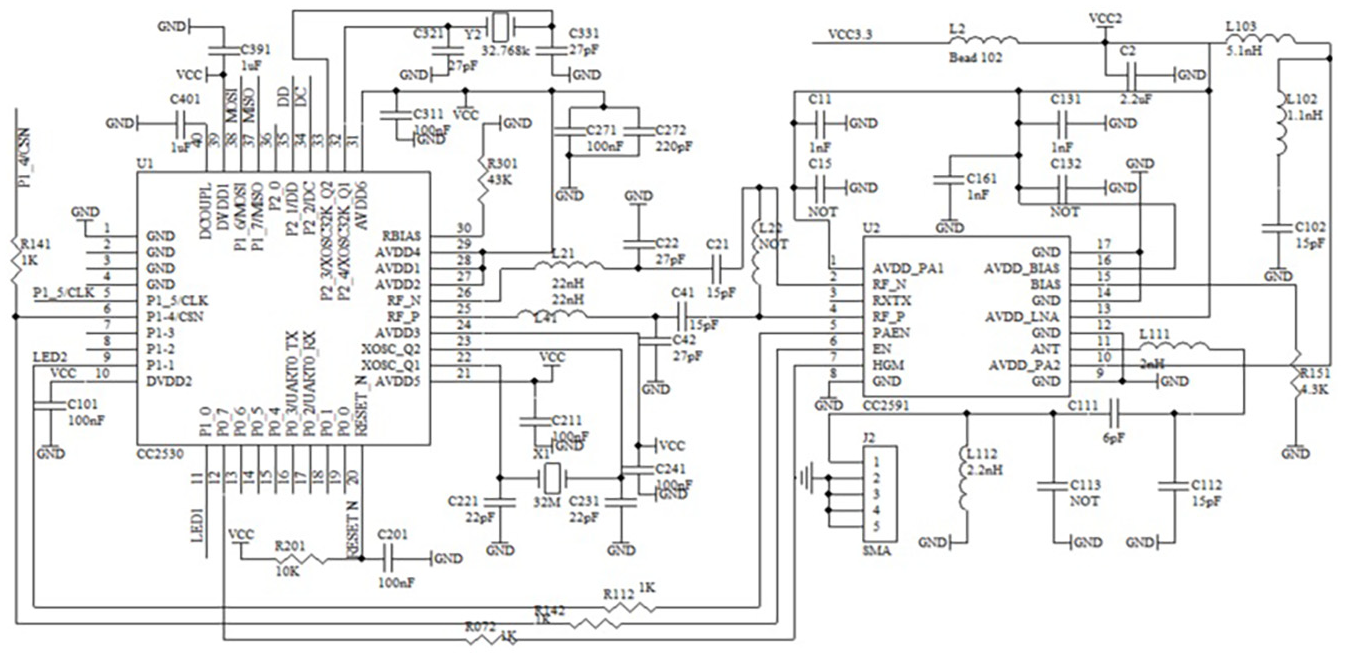
Router is the repeater station of WSN. WSN node can join the ZigBee network through the router, thus extending the whole network. It can receive the data from the node and send those related data to the coordinator so that the network planning of large-scale node network can be realized. Circuit diagram of router is shown in Figure 3.
Schematic diagram of route.
Design of coordinator circuit
As the gateway of WSN, the coordinator plays a major role in the construction of the whole network. It receives the data from the router and achieves the data communication by the serial port to the PC machine or network server. Then, the data saved at the data terminal can serve as the source of the following storage, analysis, and application of big data. Using CC2530 chip, serial communication interface can be extended on the basis of CC2530 typical application circuit. Using MAX232 chip, the electrical level change between time to live (TTL) and RS232 can be achieved. Circuit diagram of coordinator is shown in Figure 4.
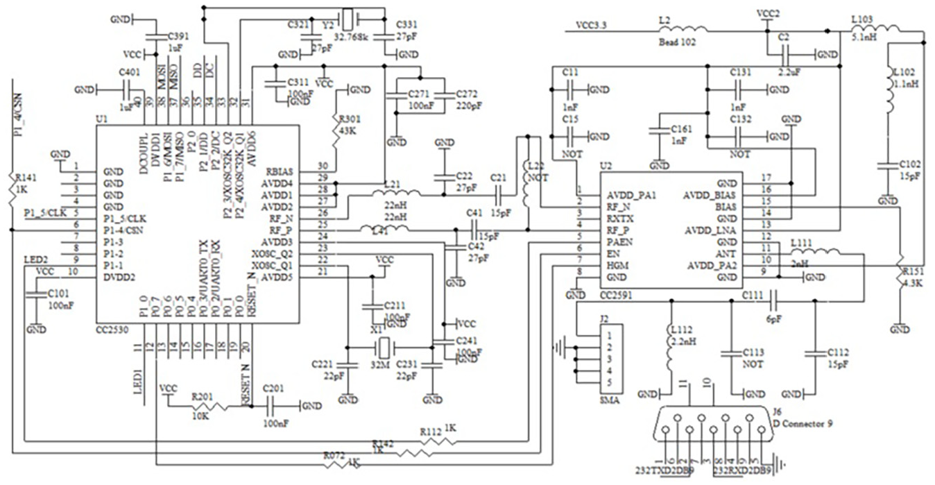
Schematic diagram of coordinator.
Design of system software
The design of the software consists of two parts. One is the ZigBee network communication program based on time synchronization with the WSN node, router, and coordinator. The other is the centralized control system of data based on big data analysis. The former completes the collection and transmission of basic data and the latter is in-charge of the analysis and application of big data. The main focus of this article is on the design of the first software.
WSN communication software is made up of the node main program, node acquisition and processing subprogram, node transmission subprogram, router main program, router transceiver subprogram, coordinator main program, coordinator transceiver subprogram, and so on.
Flowchart of the node program is shown in Figures 5–7. The principle and structure of the router program and the coordinator program are roughly the same to that of the node program.

Main program flowchart of node.

Flowchart of node acquisition and processing subroutine.
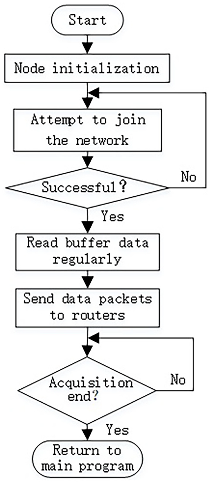
Flowchart of node sending subroutine.
The node main program includes CC2530 initialization, CC2530 drive, and time synchronization protocol.17–19 The data sending program of CC2530 packages and handles the data according to ZigBee protocol, and then completes the wireless sending of data along with time synchronization protocol. If the data receiving program can receive frames from the wireless network, the program will automatically step into interrupted service subroutine, and in this way, interrupt function can extract the received data. A detailed introduction to the AERBS algorithm will be published separately.
Test and analysis
Analysis of transmission delay of synchronous message
The local time stamp needed by the time synchronization algorithm can be gained at any layer in the network protocol stack. However, when two sensor nodes exchange synchronous data packet, the local time stamp in the packet will have to face additional synchronous uncertainties (time delay) at each layer, as shown in Figure 8. If the local time stamp is drawn out at a physical layer, then time synchronization process will only deal with uncertainties such as coding or decoding time and media transmission time.

Time delay of different layers in network protocol stack.
But, in most cases, the aforementioned factors can be nearly ignored as far as the requirements of synchronization accuracy are concerned.
Description of time synchronization test diagram
The test scenario schematic diagram in the WSN time synchronization test experiment is shown in Figure 9. The details are as follows: within an area of 100×100 m2, the monitoring sensor nodes of designed PV modules are deployed symmetrically every 25 m in the total length of 100 m. Meanwhile, at the point of 50 m, a sink node is deployed which has the same hardware structure with the monitoring sensor nodes of PV modules. The synchronization accuracy is accordingly analyzed based on the time data of node A, node B, and node C in Figure 9.

WSN time synchronization test diagram.
Analysis of time synchronization message overhead
The single-hop communication distance of WSN nodes determines deployment modes and construction of time synchronization topology. Usually, the communication distance between each node will be affected by factors such as the transmission power of the radio frequency module or the obstacles in a node deployment scenario. To facilitate further analysis of the impact of synchronization topology on message overhead, first the single-hop communication distance of the sensor nodes monitored by PV modules in the synchronous system is tested. In the test of single-hop communication, the transmission power of radio frequency module of the sensor node will be set to 3 dBm. Afterward, the packet loss rate will be introduced to measure effective single-hop communication distance between the sensor nodes. In terms of different sizes of data packet, the dependency of the packet loss rate of the sensor nodes in the process of receiving data on the physical linear distance between each node is shown in Table 1.
Experimental data of packet loss rate based on communication distance.
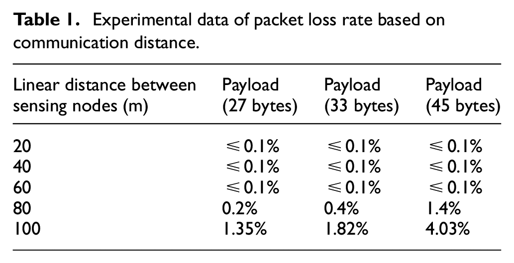
As seen from Table 1, when the linear distance between each node is less than 60 m, the packet loss rate of the received data is at a low level, which is less than 0.1%; when the distance is more than 60 m, the packet loss rate of the received data increases accordingly.
The WSN time synchronization test diagram in Figure 9 and test data in Table 1 suggest that both node A and node B can communicate with other eight sensor nodes in a single hop. Therefore, on the basis of the adaptive synchronization strategy of AERBS algorithm, the synchronization overhead of the test scenario shown in Figure 9 can be achieved, as shown in Table 2.
Comparison of packet overhead in time synchronization test.

RBS: reference broadcast synchronization; TSP-GDM: time synchronization protocol with Gaussian delay model; ERBS: energy-efficient reference broadcast synchronization; AERBS: adaptive energy–efficient reference broadcasting synchronization.
Table 2 shows that the adaptive time synchronization algorithm introduced by AERBS makes the synchronization message overhead of the algorithm less than that of RBS, TSP-GDM, and ERBS algorithms. It can be concluded that the AERBS algorithm can have a wider application in the typical WSN topology, as shown in Figure 9, and thus, a higher synchronization energy efficiency.
Test and analysis of time synchronization accuracy
In most cases, the accuracy of WSN time synchronization is measured by time synchronization error value, but in actual tests, the real clock deviation value between the WSN sensor nodes which requires a large number of global positioning system (GPS) timing modules is always unavailable. For this account, with a view to measuring the accuracy of time synchronization algorithm effectively, the maximum dispersion of estimated clock deviations is herein introduced that in WSN network a relative value of a reference time point between the nodes instead of an absolute time value is needed. 20 The smaller the difference between clock offset compensation values is, the more stable the synchronization algorithm is. So the time order between the nodes in WSN is given. The test data of synchronization accuracy of various time synchronization algorithms are listed in Table 3. Among them, the experimental data, with µs as the unit, are the average of 30 repeated experiments.
Test data of synchronization accuracy of different time algorithms.

RBS: reference broadcast synchronization; TSP-GDM: time synchronization protocol with Gaussian delay model; ERBS: energy-efficient reference broadcast synchronization; AERBS: adaptive energy–efficient reference broadcasting synchronization.
It can be seen from Table 3 that the synchronization accuracy of the AERBS algorithm is more than that of RBS, TSP-GDM, and ERBS algorithms. The main reason is that the AERBS algorithm adaptively determines the number of nodes participating in synchronization by considering node accuracy conditions and energy consumption conditions. The nodes participating in synchronization only need bidirectional time stamp exchange of sensor node pairs to achieve synchronization. So with the same time synchronization accuracy, AERBS is more applicable in large-scale networks with greatly reduction in the time of synchronization and overall energy consumption for global synchronization.
Conclusion
The system uses WSN nodes to collect voltage, current, illumination, and temperature of PV modules. A ZigBee network with AERBS time synchronization algorithm is achieved and thus, the real-time collection and transmission of running state of components are realized. In addition, the abnormal diagnosis of the PV modules through big data analysis is accordingly completed. The experimental results demonstrate that this system has achieved the monitoring function of PV modules and time synchronization among nodes. Further analysis of big data is about to attract more scholarly attention in the near future.
Footnotes
Handling Editor: Victor Hugo C de Albuquerque
Declaration of conflicting interests
The author(s) declared no potential conflicts of interest with respect to the research, authorship, and/or publication of this article.
Funding
The author(s) disclosed receipt of the following financial support for the research, authorship, and/or publication of this article: This work was supported in part by the National Natural Science Foundation of China under Grant No. 61561020, 61661020.