
Abstract
Wireless sensor networks require time synchronization, which is the coordination of events or actions to make a system operate in unison. In this work, real experiments and a theoretical analysis of the behavior of the clock sources, most used in wireless sensor networks, have been carried out. The experiments have been performed on two real platforms from two different manufacturers in real environments with sudden changes in temperature. Complementary metal-oxide-semiconductor oscillators have a low accuracy, bigger than 500 ppm, and a high dependency with temperature. External crystal oscillators have good accuracy, around 20 ppm, and are stable with temperature. Temperature-compensated crystal oscillators are very accurate, around 5 ppm, and the temperature has no influence in their drift. The use of phase-locked loop circuits minimizes the impact of temperature and stabilizes oscillators. We highlight and demonstrate the importance of the early stages of design, especially the selection of the clock source, because that decision has a great impact on the performance of the time synchronization in wireless sensor networks.
Introduction
Wireless sensor networks (WSNs) are distributed networks of tiny low-power devices capable of performing sensing and communication tasks. Their objective is to collect information from different nodes in order to have a broader view of the environment than each one would have individually.
In order for a WSN as a whole to operate properly, the time coordination of the different elements that compose it is required, mainly those that are necessary for the wireless communications and for all the actions that must be executed simultaneously in the different nodes for the correct operation of the application. If these actions are synchronized properly, communication collisions will be minimized, thus avoiding re-transmissions and helping to save energy. Similarly, if the acquisition of data by the sensors is synchronized, they will give a true picture of the monitored area.
Time synchronization (TS) is the coordination of events to make a system operate in unison. Synchronizing a network of
To create a common notion of time, it seems that it might be enough to set all the clocks in the network to start at the same time. However, reality says that the clock rate of a node depends on conditions, such as the ambient temperature, the supply voltage, and the age of the oscillators, all changing over time. 8 Moreover, each sensor node has different initial clock values. On one hand, the initial value of the clock is set to different values during manufacture. On the other hand, to save energy, the nodes in the WSN can go through different cycles of sleep and active states based on external events detected. Thus, clock error (deviation) is inevitable. 9
Our contribution in this empirical study is to highlight the importance of early-stage design decisions, such as the selection of the appropriate clock source. For that reason, we have focused this article on the hardware elements that affect the problem of TS, the clock sources. Specifically, the performance of different types of clock sources has been measured through multiple tests with real WSNs. In addition, the ambient temperature has also been taken into account as it can significantly affect the performance of some clock sources.
TS is an important issue to consider in the design, not only due to the proper functioning of the application but also regarding the energy savings. This article aims to identify the best clock sources for WSNs, emphasizing the importance and ability of earlier stage design decisions to influence sustainability, performance, and life cycle cost.
The objective of this empirical study is to prove that if we are able to improve the stability and accuracy of the clock source on which our synchronization is based, the synchronization protocols will need to perform fewer re-synchronization rounds and, therefore, our networks will be synchronized more accurately for longer time spans. Knowing the performance and behavior of the clock source of a WSN allows the developers to address certain TS problems at an early design stage. In this way, it will be easier for the developers to solve future problems with the implementation of software protocols. Addressing the problem in the early phases of design will allow the developers to have a WSN with a more robust and stable TS. In addition, analyzing the clock sources of our sensor nodes and understanding what type of clock is appropriate in each case will help the developers to better design and understand the operation of TS in WSNs. This article is aimed to enable designers of WSNs to compare and evaluate the consequences of using different clock sources, based on their empirical behavior. Starting with early design decisions is always better, for example, starting in the hardware design phase, so as to minimize the defects in the later stages, such as, in the software development.
This article is organized as follows. The “Related work” section shows the related work around clock sources, and the “Clock terminology” section clarifies some clock terminology. The analysis of theoretical behavior is presented in the “Analysis of theoretical behavior” section, and the experiments are shown in the “Real experiments” section. Finally, a discussion is shown in the “Discussion” section, and the conclusion is in the “Conclusion” section.
Related work
Several studies have pointed out the importance of the early phases of new product development projects in different fields, such as medicine 10 or building construction, 11 to name a few. The importance of the early-stage design decisions has to do with a number of critical decisions that have great impact on the performance of product development, in our case, the performance of a WSN. Any fault occurring in these early phases in understanding the importance of TS in WSNs becomes a problem to solve in the future.
The task of clock synchronization in WSNs is typically carried out by synchronization protocols rather than by specific hardware solutions. 12 Due to the impact that TS has on the proper functioning of a WSN, during the last years, there have been many analyses, surveys, and protocol developments around this topic. Most of these developments and analyses focus on software protocols that are implemented in the nodes that form the network. Many of those cases are ad hoc developments for a specific hardware. Most of the works around TS in WSNs do not take into account the clock source used. Those works mainly focus on what procedures and software corrections must be carried out to maintain the time error bounded in the nodes.4,13–15 If we reduce the field and focus exclusively on the analysis, performance evaluation, or performance comparison of clock sources, the number of works in the scientific community is drastically reduced. 16
The use of synchronization protocols allows us to dynamically correct the deviation of the clock and, therefore, limit the error in TS of the network. However, the selection of the most appropriate clock source for a certain application will reduce the number of operations to be performed by these synchronization software protocols, thus achieving a more efficient and robust operation.
We must keep in mind that the clock directly depends on the ticks generated by the oscillator. The oscillator can vary its frequency due to changes in aging, temperature, battery charge, pressure, and so on. 8 There are specific studies on the sensitivity of quartz oscillators; 17 ad hoc developments of clock oscillators, such as Oven-Controlled Microelectromechanical Oscillators (OCMOs) 18 or complementary metal-oxide-semiconductor (CMOS) oscillators; 19 and analyses about the influence of temperature on the clock skew of the nodes. 20 Therefore, the better and more stable the oscillator is, the better results its clock gives. The most common oscillators to create clock sources for WSNs are summarized here: relaxation oscillators, Basic Crystal Oscillators (XOs), and temperature-compensated crystal oscillators (TCXO).
Relaxation oscillators
The most simple and inexpensive kind of oscillators consists of a feedback loop that repetitively charges a capacitive load through a resistance until it reaches a threshold level, and then discharges it, beginning the cycle anew. They are called resistor-capacitor oscillators if the components needed to build them are resistors and capacitors, or CMOS oscillators if they are based on CMOS digital logic inverters. During the rest of the article, we will only talk about the CMOS oscillators, since they are the type of relaxation oscillators that we use in our tests. This kind of oscillators is not very accurate.
The approach of DiStiNCT work 21 is to use the internal CMOS oscillator of the microcontroller as clock source of the nodes. This kind of oscillator has an accuracy up to 15,000 ppm instead of the typical crystal oscillators with 10 to 100 ppm. They use this solution arguing some advantages, such as reduced power requirements, improved ruggedness, and the ability to integrate the microcontroller and the clock source on the same chip. When talking about TS, this kind of imprecise oscillators is not usually considered as a clock source in WSN. However, DiStiNCT achieves a mean TS error of 6.6 ms with nine sensor nodes, which is a remarkable result.
Piezoelectric resonator
An XO is an electronic oscillator circuit that uses the mechanical resonance of a vibrating crystal of piezoelectric material to create an electrical signal with a precise frequency. The most common type of piezoelectric resonator used is the quartz crystal, so oscillator circuits incorporating it became known as crystal oscillators.
The quartz crystal oscillators are attractive because they are cheap, small, use a little amount of energy, and work surprisingly well despite their low resource requirements.
The frequency accuracy of an XO is in the order of
There are many variations of XO, such as TCXOs (cost over
A comparison of oscillators’ accuracy can be seen in Table 1. 22 Through this comparative table, it is observed how their accuracy improves as their cost increases, so there is a trade-off between the quality of the oscillator and its price.
Comparison of oscillators’ accuracy.

XO: crystal oscillator; TCXO: temperature-compensated crystal oscillator; OCXO: Oven-Controlled Crystal Oscillators; MEMS: microelectromechanical systems.
Most WSNs make use of XOs as oscillators to build their clock source. If not specified otherwise, we must consider that the clock source of a WSN is based on an XO.
Whether based on CMOS oscillators or on XOs, it is possible to create the so-called real-time clock (RTC), as explained in the “RTC” section. The practical solution for TS in WSNs proposed by Coca and Popa 23 makes use of RTCs. Authors say that when a local RTC is involved in the system, there is no need for time corrections if the local clock skew is low enough and/or the re-synchronizations are made frequently. Both for short- and long-term situations, the local RTC is a good solution in terms of energy requirements and stability. So in that work, they use an RTC as a high-precision and low-energy solution. For many applications, this cannot be considered high precision, but for some others it is a good enough solution.
Based on the same idea of using RTCs, the work developed by Mohammadmoradi et al. 24 uses an RTC in one of the nodes in the network to improve the robustness of TS. In a further work, 25 they make a new proposal where the network is synchronized using several RTCs. The main idea is based on the stability of the RTCs. The researchers state that if all RTCs in the network start synchronized, the global synchronization will stay stable.
As it has been observed, although the work in synchronization in WSNs is extensive, there are few works that take into account the clock sources when designing synchronization strategies. However, the selection or consideration of the clock source should be of greater importance when evaluating and designing TS strategies in WSNs. The purpose of this article is to reaffirm the critical role of early-phase clock source selection and to encourage WSN developers to value and conduct early-phase studies for their proper objectives. That is why this work makes an empirical study with a performance evaluation of different clock sources in WSNs.
Clock terminology
In order to correctly understand the analysis and empirical study performed, it is necessary to clarify some terms.
Accuracy versus precision
All clock sources in a WSN are based on some kind of oscillator. The accuracy of an oscillator represents how much the frequency of the oscillator can deviate from its nominal value and it is expressed in parts per million (ppm).
Figure 1 shows a graphical explanation of the terms accuracy and precision. Accuracy refers to the closeness of a measured value to a standard or known value. In measurement theory, the accuracy is known as systematic error (due to measurement bias). Precision refers to the closeness of two or more measurements to each other, and in the measurement theory, this term is known as random error (due to measurement variation). During the present work, that differentiation between both terms will be of crucial importance for the evaluation of the different clock sources.

Graphical explanation of the term’s accuracy and precision.
Logical clock
Basically, a logical or electronic clock, from now on simply a clock, is a device that counts events, indicating the passage of some time interval in an electronic device. 26 The quality of a clock normally boils down to the stability of its frequency, that is to say, the ability of its frequency to emit events at a constant frequency over time.
Each sensor node has its own hardware-based clock that can be used to assign timestamps to events that occur in the system. The clock is based on the count of an oscillator at a given frequency and it is stored in a register of the microcontroller.
RTC
The term real-time clock was created to differentiate this type of clocks from the logical clocks, which simply measure the time counting pulses of a signal, without being directly related to temporal units. RTCs are more similar to the clocks and calendars we use regularly, and they work with seconds, minutes, hours, days, weeks, months, and years.
RTCs have the advantage of providing greater stability and freeing the system from having to perform time accounting. In addition, frequently the RTC incorporates some type of battery. This is a backup to maintain the time value in case of loss of power or in cases in which the microcontroller enters in modes of low consumption.
In general, all RTCs are configured to generate an interruption every second. That is why most of them are based on 32.768 kHz
Formal definition
Even though the frequency of a clock changes over time, for relatively extended periods of time, it can be approximated with good accuracy by an oscillator with a fixed frequency.
27
Equation (1) shows the value of the clock

where
Continuing with the terminology used by Paxon et al. 28 and Sundararaman et al., 29 we differentiate the following three terms:
Offset is a delay of a given clock source or the difference between two clocks. It can be measured in time units or phase degree. The offset of the clock
Skew is the difference between the frequencies of a given clock and the reference clock. We use the term skew to refer to the first derivative of the clock value with respect to time,
Drift is the second derivative of the clock value with respect to time, namely,
A graphic representation of the previous terms can be seen in Figure 2.

Clock terminology: graphical behavior of the clock components over time.
Analysis of theoretical behavior
We will use the following three groups in order to cover the most used clock sources in WSN:
RTC based on the internal CMOS oscillator of a microcontroller,
RTC based on an external 32.768 kHz oscillator (XO),
RTC based on a temperature-compensated oscillator (TCXO).
Therefore, an analysis of the theoretical behavior and the practical experiments will be carried out for each of these groups. The behavior of these groups must coincide with the analysis carried out by the manufacturers in their respective datasheets.
The purpose of these analyses is to be able to compare these theoretical data with the empirical results that is shown in the “Real experiments” section. All clock sources have been used as the basis of an RTC. In this way, the theoretical analysis and experiments are more easily comparable, and the conclusions are more clear. The results obtained are easily extrapolated to any other clock source. Two sources of clock with different frequency of oscillation, that is to say, with different granularity between generated events, but with the same accuracy in ppm, cause the same deviation after an equal interval of time.
Among all the environmental factors that can affect the behavior of clock sources, the most relevant parameter is the temperature. Considering the temperature as the fundamental parameter that causes changes on the skew, the rest of the parameters can be considered negligible. 8 This is why in this article all skew variations are considered due to changes in temperature. A null offset has also been considered throughout the work, simplifying the analysis and making the results more intelligible.
Figure 3 is an example of a TCXO DS3231 showing the behavior of typical uncompensated crystal oscillators against temperature.
30
The figure compares how an XO and a TCXO are affected due to changes in temperature. Dashed lines represent the range of ±20 ppm for the XO. That figure shows the general behavior of an oscillator, and how it slows down at cold and hot temperatures and how its tolerance increases up to

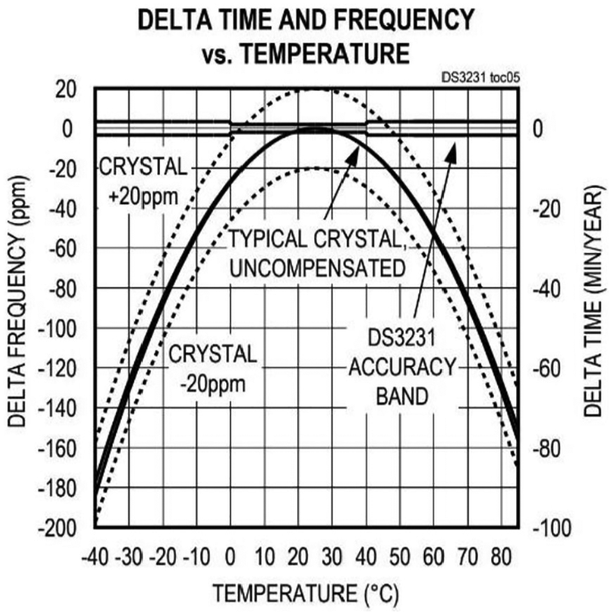
Example figure of a DS3231 TCXO where the behavior of a typical uncompensated crystal oscillator and a compensated oscillator can be seen. The figure shows how an oscillator slows down at cold and hot temperatures.
Giving a real example with a working temperature of
RTC based on internal CMOS oscillators
CMOS oscillators have a high skew and drift. These are the most used and basic solutions for a clock in modern microcontrollers. They are usually able to operate in all low consumption modes. We include in this group all the oscillators with an accuracy bigger than 100 ppm. In our theoretical analysis, we take a clock whose skew grows linearly at an average rate of 1000 ppm (86.40 s/day, 8.76 h/year).
Deviations in an oscillator can be both positive and negative, meaning that in some cases the deviation is increased and in others it is decreased. In Figure 4, it is shown only the absolute value of the maximum, that is, the worst case. In Figure 4 (left), we can observe the evolution of deviation in minutes of a 1000 ppm oscillator. The theoretical analysis was done at

The absolute maximum of the theoretical value of the deviation of an oscillator with different accuracy (yellow bars) and the influence of constant temperature (±10°C red bars, ±20°C blue bars) with 1000 ppm oscillator (left) and with 2 ppm oscillator (right).
RTC based on external crystal oscillators
Clocks based on XO to generate RTC are more stable than those based on CMOS. These kinds of clock sources are usually able to operate in low-power and sleep modes, but not in stop modes.
We are including in this group all oscillators with a precision between 10 and 100 ppm. The typical frequency of an oscillator that is used for an RTC is 32.768 kHz, which gives us a granularity of 30.5 µs. Its skew grows linearly but much more slowly than in CMOS. In this case, we analyze clocks with 20 ppm (1.73 s/day, 10.51 min/year) without changes in temperature. If the temperature grows till
RTC based on external temperature-compensated oscillators
A TCXO can minimize the deviation due to temperature changes, creating a clock source much more stable than a normal XO. We include, in this group, all those clock sources with a precision deviation lower than 10 ppm. For these theoretical analyses, we use clocks with 2-ppm accuracy (0.17 s/day and 1.05 min/year). Usually, they are able to operate in all modes because they have their own external battery. In these cases, the information from the clock source to the system will be only available in running modes via serial communications.
We can see in Figure 3 how the TCXO is much more stable than an uncompensated XO.
30
In Figure 4 (right), we see the deviation in seconds of a 2-ppm oscillator with temperatures of
The additional deviation due to temperature variations is the same regardless of the base ppm of the clock source, but the relative percentage due to temperature in the 2-ppm clock is greater than the deviation of 2 ppm itself, which means that the temperature has a bigger impact on oscillators with better accuracy.
Table 2 shows the maximum time intervals between re-synchronization rounds in a WSN to keep the synchronization error between nodes below a certain level (columns) based on the accuracy of the oscillator used (rows). For example, for a clock source that deviates 20 ppm, if we want an accuracy below 1 ms, we need to re-synchronize every 50 s. The table is created based on equation (3), where the necessary time (Round Interval) to reach a certain time error using a specific oscillator accuracy is calculated

Relation between oscillator quality and maximum synchronization error allowed.

In this way, Table 2 provides a quick method of evaluating the synchronization requirements of a WSN. For example, setting the premise of not wanting the synchronization messages to collapse the network, and therefore restricting to a maximum of one message every 0.1 s, we can see that the synchronization with a maximum error of 1 µs is unfeasible for systems with clock sources over 20 ppm. In less demanding applications, where a maximum error of 1 ms can be allowed, we can use almost any clock source, always bearing in mind that the better and more stable our clock source is, the fewer messages and operations we need to maintain synchronization.
Real experiments
Scenario
The objective of conducting experiments on a real WSN is to verify that the hypotheses assumed in the theoretical analysis are correct. Even so, when performing experiments in real scenarios, there are circumstances that are difficult to analyze in theory or that have been overlooked, such as hardware differences and interactions between nodes.
The experiments make use of several scenarios, but all of them have the same basis, as can be seen in Figure 5. The reference node has a CMOS, an XO, and a TCXO, and it is connected via serial communications with a computer. The computer is running with Windows 10, and the Windows Time Service is configured with phase correction adjustments every 86,400 s (24 h) against an network time protocol (NTP) server. All nodes cohabit in two environments, where the temperature is controlled thanks to an additional two sensor nodes, one near the reference node, at ambient temperature above

Graphical representation of the WSN scenario.
To test the behavior of the clock sources under temperature changes, in some of the tests, a set of nodes was placed inside and outside of the
Measurements and comparisons between the different RTC clocks have been made. We have tested and compared the behavior of CMOS clocks, based on an internal CMOS oscillator of 32 kHz without and with calibration. External oscillators of 32.768 kHz of 20- and 100-ppm quality have also been tested. We have also evaluated several DS3231 TCXOs. In addition, to evaluate the behavior of the main clock in WSNs, experiments have been carried out with the high-speed external (HSE) clock that is normally based on an external oscillator (16 MHz in our case) and some type of internal phase-locked loop (PLL) that increases its speed (96 MHz in these experiments). Finally, although all the experiments have been carried out on the hardware platform explained in the “Hardware platform” section, a new test has been performed on a device from a different vendor.
Each node sends the value of its local clocks every several seconds. In the reference node, all data are collected by marking the arrival time via software in the MAC layer and aggregating the data to a common file. This will allow us to check the deviation between all the node clocks and the reference one. Multiple experiments have been performed to compare the three clock sources under evaluation.
Hardware platform
We have used the development board STM32F411 DISCO from STMicroelectronics to carry out the experiments. We have chosen this development board as an example of a commercial board that can be used in WSN. A radio transceiver has been added to the development board to add wireless communication capabilities.
For STM32F4xx boards family, the low-speed internal (LSI) clock accuracy is not recommendable for calendar applications. 32 The LSI clock is neither factory calibrated nor very accurate. Typically, its frequency is between 30 and 60 kHz. The LSI clock incorporated in the STM32F4xx boards is the example of CMOS oscillator to be tested. This kind of oscillator, unlike the other oscillators in the system, acts as a low-power clock source that can be kept running in Stop and Standby modes. In this board, all internal clocks except LSI are stopped in Stop mode. 33
A standard external 32.768 kHz 20 ppm XO, a DS3231 TCXO, and the main HSE at 96 MHz are the other three clock sources under comparison.
As commented before, a similar device from a different vendor has been tested to compare the behavior between vendors. Most of the tests have been done with an STMicroelectronics platform. In this case, to evaluate whether the microcontrollers’ manufacturers have any effect on the behavior of external oscillators, a platform from different vendor has been selected. The platform selected is an Arduino UNO R3 which is based on a Microchip ATmega328P with an external crystal oscillator of 16 MHz. The most remarkable results are shown in the “Experiment with CMOS clock sources without calibration,”“Experiment with CMOS clock sources with calibration,”“Experiment with external 32.768 kHz clock sources,” and “Experiment with TCXOs” sections.
Experiment with CMOS clock sources without calibration
Table 3 shows the values of the frequencies after a performance measurement of the clock sources of the STM32F411 boards as they came from factory using the standard prescalers for a 32-kHz clock source. We can see that the differences and the corresponding ppm associated with each clock source are enormous. Because of that low accuracy, these are not recommended for most synchronization applications. All these clock sources exceed 1000 ppm; some even reach 100,000 ppm.
Measured factory deviation of LSI clocks without calibration compared with an ideal 32 kHz clock.

Figure 6 shows how the clock sources based on two TCXOs and four internal CMOS deviate with time. The NTP clock is the reference one and its line is almost invisible since it is superimposed by the TCXO clocks. In this case, it is remarkable to see how much the CMOS oscillators with factory defaults’ prescalers deviate. The CMOS oscillators with the maximum and minimum deviation are the ones with 12.44% (124,441 ppm) and 0.65% (6534 ppm), all over 1000 ppm. Using this kind of CMOS oscillators as clock sources, as they came from factory, makes the influence of temperature irrelevant because they deviate so much that the influence of additional factors goes unnoticed. When making the scale so large with the deviation of the CMOS, it seems that the rest of the clock sources represented, such as the external XO oscillators and the TCXO, do not deviate at all, but we will see their behavior in more detail in the next figures and experiments.

Long-term experiment with non-calibrated internal CMOS oscillators. Two nodes are at room temperature (yellow and green lines) and other two nodes alternate between room and cabin temperature (cyan and magenta lines).
Every clock has been approximated through a basic linear fitting giving an expression similar to equation (1). In this way, we can differentiate their offset and skew (Figures 6 and 8). The difference between the real data and the fitting line is the accumulated drift over time (Figures 7 and 9). The mathematical expressions of every clock are over-impressed in the figure. It has been proven through several performance measurements that the CMOS oscillators in long-term experiments tend to deviate the same percentage. Their skews grow linearly and they are precise but not accurate.

Accumulated drift of non-calibrated internal CMOS oscillators versus temperature: room temperature in (left) and drastic temperature changes in (right). The accumulated drift follows an ascending line when the temperature falls and a downline when the temperature grows.
In Figure 7, the accumulated drift (skew variation) over time of the clock is shown in relation to the temperature variation. In the experiment carried out, two of the nodes were at room temperature (left) and two were subjected to sudden changes in temperature (right).
We can observe how in both cases, at room temperature and with drastic changes in temperature, the accumulated drift follows the same pattern. As a general rule, we can infer that the accumulated drift carries an ascending line when the temperature falls and a downline when the temperature grows.
Experiment with CMOS clock sources with calibration
Knowing the factory oscillation frequencies, and using more appropriate values for the prescalers for the RTC clock, allows us to adjust its frequency to be more accurate.
Once we verified that the CMOS oscillators of the STM32F4xx boards are not factory calibrated and that they deviate greatly from the theoretical 32 kHz, an adjustment of their prescalers was made to adjust their values to those of an RTC. Once adjusted, the previous experiment was repeated. Their results are shown in Figure 8.

Long-term experiment with calibrated internal CMOS oscillators. Two nodes are at room temperature (yellow and green lines) and other two nodes alternate between room temperature and cabin temperature (cyan and magenta lines). A pointed line represents the linear fitting behavior of each node’s clock.
We note that the accuracy of the clocks can be now expressed in ppm, with maximum and minimum deviations of 3008 and 507 ppm. This new experiment allows us to observe some behaviors that could not be detected in the previous ones due to the calibration.
Now, we observe how the influence of the temperature makes it possible to differentiate the skew from the accumulated drift. The skew grows linearly, but the drift does not, and directly depends on temperature changes.
As in the previous case, the accumulated drift has been represented in relation to the temperature variation. Figure 9 (left) shows the nodes at room temperature and Figure 9 (right) corresponds to the nodes subjected to sudden changes in temperature.

Accumulated drift of calibrated internal CMOS oscillators versus temperature: room temperature (left) and drastic temperature changes (right). The skew grows linearly, but the drift does not, and directly depends on temperature changes.
The behavior of CMOS oscillators against the temperature in this experiment is very similar to the previous case but with different ranges since they have been calibrated.
Experiment with external 32.768 kHz clock sources
The behavior of the external clock sources used is shown in Figure 10. Figure 10 (left) shows a global view to see how the external oscillators vary in magnitude in relation to a CMOS oscillator. It can be seen that the external oscillators are much more accurate and precise than those based in relaxation oscillators.

Long-term experiments with external 32.768 kHz oscillators: it can be seen how the accuracy of the external oscillators is better than that of the LSI by several orders of magnitude (left), and the same figure is plotted without the LSI line (right).
In Figure 10 (right), we have eliminated the CMOS line to observe the detail of the external clock sources. In this case, we can see how the external oscillators of 32.768 kHz behave as expected and within the margins marked by their datasheets, two of them of 20 ppm and another of 100 ppm. The oscillators reach deviations of −3, −17, and 67 ppm. Repeating this experiment under the same conditions, it is observed that the results are very similar demonstrating that the external oscillators are precise.
Experiment with TCXOs
In all the experiments and in all the previous figures, the TCXOs have been plotted. Their results are so close to the 0-ppm reference that in most cases their lines overlap. We corroborate that their drift is very low independently of the temperature changes, resulting in a maximum and minimum deviation of 4 and 0 ppm in our experiments. An example of how much the drift deviates with temperature in the case of an XO and a TCXO is shown in Figure 11.

Stability of an XO and a TCXO under drastic temperature changes.
Experiment with HSE oscillator
The main clock in most of the devices chosen to create WSN is based on external crystal oscillators. Then the base frequency of the oscillator is increased through a PLL generating the final frequency at which the device works. In this experiment, the crystal oscillator has a frequency of 8 MHz, and after the PLL process, the frequency is increased to 96 MHz.
This experiment aims to show the behavior of the HSE main clock versus temperature changes. The same scenario has been used as in the previous experiments, but in this case taking the local timestamps of the nodes using the 96 MHz HSE. The results at room temperature can be seen in Figure 12 (left) and with drastic temperature changes in Figure 12 (right).
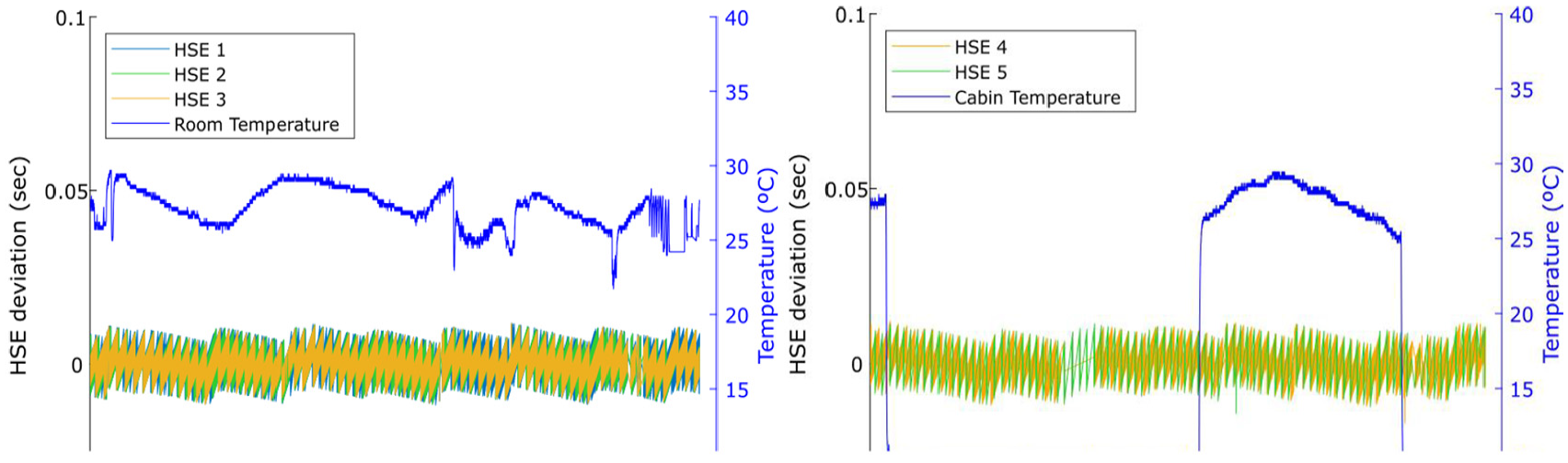
High-speed external (HSE) drift behavior under two different temperature environments: room temperature (left) and drastic temperature changes (right). The influence of temperature changes can be considered negligible for the HSE drift.
Experiment with ATmega328P with 16 MHz external oscillator
All previous experiments have been performed on the same hardware platform from the STMicroelectronics vendor. In order to have a more general idea of the behavior of clock sources in WSN, we have decided to make an additional test on a hardware platform from a different vendor. For this experiment, we have chosen the Arduino UNO R3 platform, whose microcontroller is an ATmega328P from Microchip.
The same scenario has been maintained as in previous cases, but in this case, the main oscillator of Arduino UNO, an external oscillator of 16 MHz without PLL, has been used. The results obtained can be seen in Figure 13.
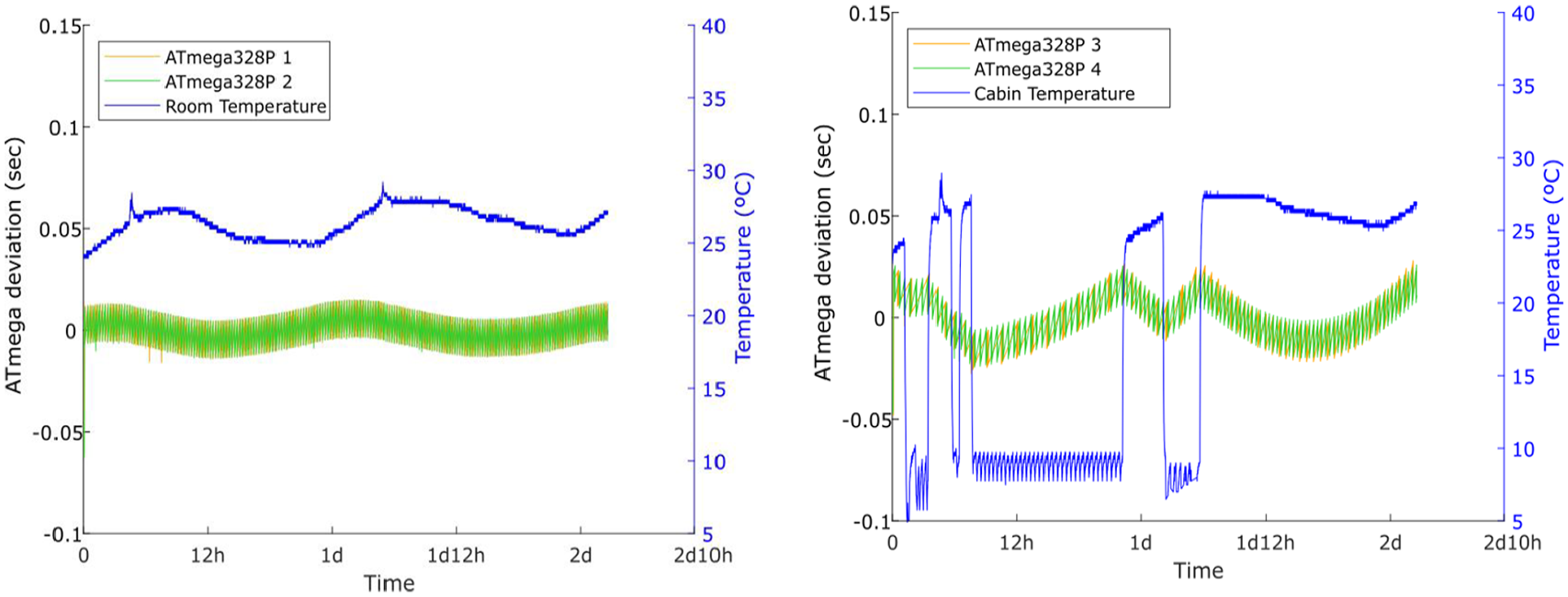
Behavior of an external 16 MHz oscillator in an ATmega328P device under two different temperature environments: room temperature (left) and drastic temperature changes (right). The cabin environment with drastic changes in temperature has more influence in the oscillators’ drift.
Discussion
CMOS oscillators
Clock sources based on CMOS oscillators are the cheapest and most integrated solutions that exist. CMOS oscillators do not require any external hardware for their operation. They offer typical deviations higher than 1000 ppm, which implies a deviation of 1.44 min every 24 h. This type of oscillators can work in sleep and stop modes, and usually they have low-power consumption. The results of the experiments validate the results of the theoretical analysis, showing that this type of clock sources has a very high drift.
Figure 6 demonstrates the huge deviation of an internal relaxation oscillator based on CMOS with factory configuration. We can deduce that the use of internal relaxation oscillators in synchronization applications, as the LSI in the STM32 boards, must necessarily pass through a previous calibration. With that calibration, the prescalers, that define when a timer event is generated in the system, can be adjusted properly. As this type of clock sources is usually not factory calibrated, it is usual for the same microcontroller model to have widely dispersed results in terms of oscillation frequency, as shown in Figure 6.
Once the calibration is done, we can see in Figure 8 that this type of clock sources is not recommended for applications with TS requirements due to the important influence that temperature has on the drift. Whether at room temperature or with sudden changes in temperature, drift caused by temperature can accumulate deviations of hundreds of seconds in a day.
Making use of both figures, we can also observe that although the clock sources based on CMOS oscillators are not accurate, they are quite precise, giving the same results throughout the different tests carried out. In the case of Figure 8, it must be taken into account that the temperature has a strong influence on the results. But even though that the behavior of the CMOS oscillators is less precise, the skew lines of the different oscillators remain stable.
Looking at Figure 7 (right) or Figure 9 (right), it is possible to see the influence of temperature over the oscillators’ skew. When there is an abrupt change of temperature, the clock drift changes. Temperature and drift variations go in different directions. When the temperature goes down, the drift goes up, and vice versa. The influence of the temperature on the behavior of a clock, as it can be seen in the graph, shows that the drift can accumulate several hundreds of seconds in CMOS-based oscillators.
Clock sources based on CMOS oscillators have a high-drift variation with environmental conditions, which makes their software correction more complicated. They are quite precise oscillators, but not accurate and with a drift very dependent on changes in temperature.
These kinds of oscillators are a recommended solution in prototypes that do not require high accuracy in time measurements or in applications where time accuracy does not affect the final result and where stop modes are needed. Due to such high-drift deviations, it is strongly recommended not to use them for the internal RTC or applications with high precision and accuracy time requirements.
External crystal oscillators
After the performance evaluation of clock sources based on external oscillators of 32.768 kHz, the theoretical analyses carried out beforehand are validated. The results shown in Figure 10 indicate that the external clock sources are adjusted to their specifications, corroborating that the measurements have been correctly taken. The results also fit with the theoretical results regarding their deviation in ppm. After the performance evaluation, we can say that external oscillators of different models are precise and accurate, and behave very similar to each other. Although it is a cheap solution, it requires additional external hardware, such as the oscillator itself and the associated capacitors.
RTC based on this kind of clock sources deviates by less than 9 s every 24 h. If an oscillator of 20 ppm was corrected every 5 s, it would maintain a precision of 100 µs. Usually, they can work in standby modes but not in stop modes. They are more accurate than CMOS oscillators but less accurate than the TCXO. They are very precise, giving the same results in the different experiments.
In Figure 11, we observe the temperature influence over external clock sources. In this graph, we have drawn a basic quadratic fitting line of the behavior of the XO and a TCXO under sudden temperature changes. We observe that the drift variation due to temperature is very smooth and practically imperceptible. An internal RTC and external RTC are equivalent regarding energy consumption. The STM32 Cube simulator estimates a consumption of
These kinds of oscillators are a recommended solution for most projects that require a good compromise between price and features.
TCXO
Clock sources using external oscillators with temperature control deviate very little, being very accurate, precise, and stable. These measures fit with their specifications, so it is proven that the measurements have been correctly made. For our performance comparison, we have used DS3231 TCXO-based RTC, which requires an external chip and serial communications, such as I2C, to transmit the information to the microcontroller. The performance of this type of clock sources has proven to be the best solution in terms of its technical characteristics, but it has some disadvantages. They are slightly more expensive than the other clock sources evaluated. In some cases—for example, for the DS3231—in order to make it work, it is necessary to configure and establish a serial communication with the microcontroller. And after that, it will be necessary to send a series of initial configuration commands to the TCXO, so that it behaves as we wish. There are other TCXO models, like Abracom ASTXR-12 which is not analyzed here, that do not require additional battery and whose configuration and communication are different.
RTC based on this kind of clock sources deviates by less than 0.5 s every 24 h. To maintain a synchronization with 100 µs accuracy, it would be necessary to perform re-synchronization rounds every 20 s.
They offer us a skew without variations due to environmental changes, such as temperature. The drift is almost nonexistent as it is shown in Figure 11. It can be observed in Figures 6 and 10 (right) how the clocks with temperature control (TCXO) remain stable in a range of less than 5 ppm regardless of the temperature changes. We can verify how the TCXO, in addition to being accurate, is precise and comparable to the quality of the periodically adjusted computer clock synchronized by NTP.
This is a recommended solution for all those applications that need to keep an exact control of the time.
HSE oscillators
Figure 12 shows that HSE oscillators are very stable clock sources and have a very low drift independent of temperature changes. These results corroborate the previous studies of Boyle et al.,
21
where the authors compare the LSI versus HSE reaching the same conclusion as this study. The HSE is a more stable and accurate clock source than the LSI. The accuracy of all tested oscillators in this work is around 50 ppm with a maximum deviation of
This also corroborates the idea that the clock sources based on crystal oscillators, independent of its oscillation frequency, are more stable and precise than those based on relaxation oscillators. This is the most recommendable option to choose if there is no low-power working states, because, usually, this kind of oscillators is switched off in low-power states.
ATmega328P with 16 MHz external oscillator
Using a microcontroller from a different vendor (ATmega328P) with an external 16 MHz crystal oscillator gives the results shown in Figure 13. The figures show that in this case, the influence of the temperature changes can be seen in the behavior of the drift. But, also, the room temperature has a light effect over the drift. The drift variation in the worse case is below
The accuracy of the oscillators measured in this test goes from 50 till 650 ppm, giving the idea that they need a calibration before they are used.
Practical considerations
Depending on the type of clock source used in a WSN, we can assure, based on the results observed in the theoretical and experimental test, that the accuracy, precision and drift are very variable.
In Table 4, there is a summary of accuracy, precision, and drift of the clock sources evaluated. We can see that the difference between the terms accuracy and precision is important, because in this work, all tested clock sources have good precision but big differences in accuracy and drift.
Summary of clock source properties.
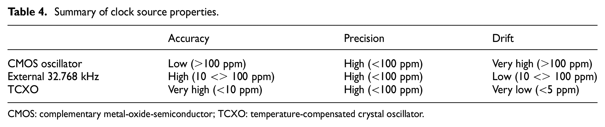
CMOS: complementary metal-oxide-semiconductor; TCXO: temperature-compensated crystal oscillator.
Keeping Table 2 in mind, we can reach conclusions to discard certain applications using certain clock sources or discard certain clock sources in certain applications. For example, it is pointless to use clock sources with deviations higher than 100 ppm in applications that require synchronization with a maximum error of 1 µs since we would have to perform re-synchronization rounds every 10 ms.
In a WSN used for structural health monitoring, the maximum synchronization error among the nodes is 1 ms, to ensure that the aggregated data are a true image of reality. To achieve this with a clock source based on CMOS oscillators, they would have to do re-synchronizations, at most, every 10 s. If an external oscillator of 32.768 kHz is used, this re-synchronization could be performed every 50 s. Finally, if we used a TCXO, the re-synchronization would only have to be executed every 200 s. As can be seen from this example, the number of messages transmitted, processing time, and, consequently, the battery consumption dedicated to the synchronization tasks will depend on the clock source chosen for the nodes of our WSN.
Analyzing the clock sources of the nodes of a WSN understanding what types of clock are appropriate in each case will help us to better design and understand the operation of the TS in WSN. If we do not take into account the behavior of the clock source, the protocols developed to keep the system time synchronized will not behave as expected. Even the same synchronization protocol can behave differently in apparently identical platforms if the chosen clock source is not the correct one for the application.
In this work, we have demonstrated a trade-off between the clock sources and their behavior against temperature. Depending on the clock source chosen for a WSN, the timing behavior will vary in accuracy, precision, and stability. A more precise, stable, and accurate clock source keeps our WSN synchronized for a longer time, helping us to perform less actions to maintain the system synchronized within some margins. In exchange for a small investment of money and additional hardware, a WSN developer can get very good clock sources that allow them to have a higher quality system clocks, with a smaller and more stable offset, skew, and drift.
Conclusion
This article highlights the importance of early-stage design decisions that affect the problem of TS in WSNs. Specifically, this work is mainly focused on the clock sources, which are the leading hardware elements that affect to the problem of TS.
The behavior of different types of clock sources, with different quality and under the influence of temperature, has been not only theoretically studied in this article but also tested in real scenarios. The representation of the analysis of theoretical behavior of the different clock sources shows how, in addition to the basic quality of the clock source, it is necessary to take into account the influence of the temperature. Depending on the type of clock source, the temperature influence can provoke high-drift variations, which makes the software correction of the TS more complicated. Those theoretical analyses have been corroborated conducting experiments of performance, where the CMOS, XO, and TCXO clock sources have been tested at room temperature and with abrupt changes in temperature. The results show that in the future, with a good modeling of the working temperature and clock sources, the theoretical calculations can give us a very good approximation of the behavior of clock sources in real environments.
A good choice of the clock source in the early phases of design of a WSN can lead the developers from failure to success. The clock source choice in the early stages of design has a great impact on the performance of the TS in WSN. The developers should always choose the clock source that best suits their needs and consider the influence of the temperature.
Footnotes
Acknowledgements
The authors also want to thank Ramiro Utrilla, Santiago Real, and Alba Rozas from B105 Electronic Systems Lab, for their comments that greatly improved the manuscript.
Handling Editor: Yi Zhang
Declaration of conflicting interests
The author(s) declared no potential conflicts of interest with respect to the research, authorship, and/or publication of this article.
Funding
The author(s) disclosed receipt of the following financial support for the research, authorship, and/or publication of this article: This research was partially funded by the Spanish Ministry of Economy and Competitiveness, under RETOS COLABORACION program (Reference grant: All-in-one: RTC-2016-5479-4) and CIEN program (ROBIM Project), and the Spanish Ministry of Industry, Energy, and Tourism through the Strategic Action on Economy and Digital Society (AEESD) under SENSORIZA: TSI-100505-2016-10 project.