
Abstract
Various technologies have been developed for the efficient use of the multiple radio access technologies resource at the radio access network level or other network levels to improve user service quality in mobile communication networks. In long-term evolution, mobile carriers are commercializing radio access network-level traffic aggregation technologies such as licensed-assisted access-long-term evolution, long-term evolution-unlicensed, and long-term evolution-wireless local area network aggregation, which use the multi-accesses of the 3rd Generation Partnership Project and WiFi, and the multipath transmission control protocol–based traffic aggregation technologies at the L3 network level. The standardization of 3rd Generation Partnership Project Release 16, which is scheduled to be completed by 2020, is under progress to support the traffic aggregation technology at the L3 network level through a multi-access 5G network. Multipath transmission control protocol is also considered as a traffic aggregation technology. However, it is difficult to apply the multipath transmission control protocol employment model used in long-term evolution to the 5G network structure as it is due to the change to a common core architecture that accommodates multiple radio access technologies through one common interface. Therefore, this article proposes an optimal 5G system architecture and a multipath transmission control protocol adaptation method to support the access traffic steering function based on multipath transmission control protocol in a 3rd Generation Partnership Project 5G mobile communication network. We have verified the development of the multipath transmission control protocol–based multi-access traffic steering technology by implementing the proposed solution in a commercial server on a testbed based on the 5G system standard of 3rd Generation Partnership Project Release 15. Furthermore, this article defines problems that occur when implementing the multipath transmission control protocol–based multi-access traffic steering system and proposes relevant solutions. Based on the implementation results, it is demonstrated that the proposed multipath transmission control protocol–based multi-access traffic steering system can perform traffic steering in the 3rd Generation Partnership Project 5G network.
Keywords
Introduction
The demand for multimedia services, such as mobile television, high-definition video, augmented reality, and virtual reality, over mobile networks continues to rise.1,2 The virtual ubiquity of multimedia-capable mobile devices and the increasing pervasiveness of the Internet of Things (IoT) are fueling demand for the higher throughputs deliverable by 5G networks. 3 However, supporting such multimedia services in terms of compression, encoding, transmission, and processing are challenging for traditional multimedia communications and processing schemes—which are thus not adequate for 5G networks. 4 Consequently, various relevant schemes have been developed, such as a transmission method that improves the quality of service (QoS) for various multimedia contents in 5G networks 5 and context-aware algorithms that improve the video compression for real-time multimedia services.6,7 However, the popularity of live video streaming together with the rapid development of mobile communications and the affordability of high-end mobile devices has led to an explosion of mobile broadband traffic that currently has the underlying networks under significant amounts of pressure. 8 Therefore, higher capacities are required to support multimedia services such as surveillance videos, voice and video, and IoT-based streams in 5G communication networks.
According to the service scenario requirements of the 5G vision presented by the International Telecommunication Union Radiocommunication Sector, the 5G mobile communication service requires an ultrawideband service that supports a speed of up to 20 Gbps, mass connections that provide 1 million connections in 1 km2, such as massive IoT, and high-reliability low-delay communication services with a delay rate of one-thousandth of a second, such as railways and autonomous vehicles. 9 The Third Generation Partnership Project (3GPP) is an organization that has led the mobile communication standards since 2015 and has completed the 5G System (5GS) Phase 1 (Release 15) standards in 2018 to satisfy 5G requirements. Currently, it is developing the standards for 5GS Phase 2 (Release 16) and aims to complete them by 2020. One of the major principles of the 3GPP 5GS architecture is the minimization of the dependency between access networks (ANs) and core networks (CNs). 10 This principle aims to enable the 5G CN to accommodate heterogeneous ANs including different radio access technologies (RATs), unlike the 4G long-term evolution (LTE) that supports only a single 3GPP AN in the 4G CN. 11 To satisfy the 5G requirement of 1000 times larger data capacity compared to 4G, 12 the common CN architecture design principle makes it extremely easy to apply traffic aggregation technologies 13 at the network level, which is required to increase capacity gain in a multi-RATs environment.
In the 3GPP 4G system, the traffic aggregation technologies at the radio access network (RAN) level, such as licensed-assisted access-long-term evolution(LAA-LTE), long-term evolution-unlicensed (LTE-U), and long-term evolution-wireless local area network aggregation(LWA),14–16 in the multi-RATs environment have been commercialized, and these technologies have contributed to the improvement of user service quality by increasing the capacity of wireless networks. 17 As the CN of LTE only supports a single AN, it is difficult to apply traffic aggregation technologies using multi-access at the network level. Hence, more diverse RAN-oriented traffic aggregation technologies have been developed. However, the requirement for large-capacity high-speed traffic cannot be satisfied only by improving the air interface. Thus, multipath transmission control protocol (MPTCP) 18 has been applied to LTE mobile communication networks. MPTCP is a traffic aggregation technology at the TCP level. 19 One characteristic of MPTCP is that it is relatively easy to provide traffic aggregation for different ANs without adding new equipment or functions to the mobile communication CN. Hence, mobile carriers provide traffic aggregation services between LTE and WiFi by applying MPTCP to the LTE network. 19 The quality of Apple Siri has been improved by applying MPTCP to manage backup TCP connections. 20 Mobile carriers have applied proxy-based MPTCP 21 to the LTE network as an overlay and provided the traffic aggregation feature using LTE and WiFi ANs without adding new functions to the evolved packet core (EPC) network. The MPTCP proxy is located outside the LTE network due to the structural limitation of the EPC network, which only supports a single AN. As a result, the traffic aggregation function is performed between user equipment (UE) and the MPTCP proxy, resulting in extremely limited control of the MPTCP-based traffic aggregation inside the LTE network.
Access traffic steering, switching, and splitting (ATSSS) is a traffic aggregation technology at the network level. It can easily expand throughput or provide redundancy under the common CN (Release 15) architecture that accommodates various types of ANs (e.g. 5G new radio (NR), WiFi, satellite, broadband fixed). The ATSSS technology began to be standardized in Release 16. 22 It aims to overcome the limitations of the MPTCP-based traffic aggregation function deployed outside the LTE network and to provide traffic aggregation more efficiently at the network level. It is an extension of 5GS for multi-access traffic steering between 3GPP ANs and non-3GPP ANs. The ATSSS technology to be implemented in UE and the network (control plane and user plane functions) proposes two methods of traffic steering, and one of them uses MPTCP, which is a representative technology to provide the ATSSS function. However, in the common core architecture, 3GPP access (e.g. 5G NR) and non-3GPP access (e.g. WiFi) are connected to one 5G core network (5GC). Due to this, to provide the MPTCP function to 5GS, we require another type of employment model that differs from the MPTCP employment model in the LTE architecture to which only 3GPP access is directly connected.
Therefore, the main issue in applying MPTCP to 5G networks is whether it can accommodate the structural characteristics of 5GS. Another important issue is whether it is possible to extend the MPTCP function to provide the various access traffic steering methods required in 5G networks, such as priority based and smallest delay, in addition to the data throughput extension and redundancy functions provided in LTE. Employment of MPTCP to LTE provides traffic aggregation at the application level without any control in the LTE network because MPTCP connections are created over LTE connected to EPC networks and wireless local area network (WLAN) connected to WiFi CN, respectively, between UE and the MPTCP proxy. 19 UE and the MPTCP proxy generate multiple paths and perform traffic aggregation on LTE and WiFi networks. Thus, access traffic steering methods are limited to the load balancing and active/standby provided by MPTCP. This implies that the MPTCP-based traffic aggregation method applied to LTE cannot be applied to 5GS, which requires a common core architecture and various access traffic steering methods.
This article proposes a model that satisfies the ATSSS service requirements of 3GPP 5GS and can apply MPTCP to 5G networks for traffic steering. Our main contributions are as follows: first, we define problems to integrate MPTCP with the 5GC. The 5G common core structure inevitably experiences the problems of one common service IP address for different ANs and data forwarding to different ANs from the common core. Therefore, to support ATSSS, this article proposes an MPTCP-based multi-access traffic steering (MATS) solution that can solve the abovementioned problems to expand the new access traffic steering method to support multimedia services. Second, we propose an architecture for the MATS solution to solve the problems of forwarding downlink traffic which converges into a gateway within the 5GC, requiring multiple MPTCP addresses for multiple ANs, and an extension of control plane functions to handle MPTCP traffic with different steering modes. In the proposed solution, the MPTCP proxy is located inside 5GC to distribute MPTCP traffic between 3GPP and non-3GPP ANs with the same control messages of 5GS, although the MPTCP proxy deployed outside LTE networks distributes MPTCP traffic between EPC networks and WiFi CNs with different control messages from the LTE system. In this manner, the proposed model is able to accommodate 5G features that are not provided in MPTCP technology and to directly reflect AN conditions. Therefore, the MPTCP-based MATS solution supports various types of high-capacity multimedia applications as the MPTCP function is easily adapted to 5GS to expand throughput based on 5G signaling. Third, we implement a testbed system of the proposed MPTCP function in 5GS. We outline its normal operation with multimedia applications and then demonstrate the functions with experimental scenarios. Finally, we derive throughput modeling and conduct numerical analysis based on the modeling to present the benefit of the proposed solution in various network conditions.
The remainder of this article is organized as follows: section “Background and related work” examines the ATSSS 22 and MPTCP 18 technologies required in 5G. Section “MPTCP-based MATS solution for Internet of multimedia” discusses the core issues in applying MPTCP-based ATSSS in 5GS and the design directions to solve these issues. In addition, an MPTCP-based MATS solution is proposed based on the designs of related functions. Section “Testbed system implementation” outlines the implementation of a testbed of the proposed system and examines the test results. Section “Throughput analysis” analyzes the MPTCP throughput under various network conditions considering the actual Internet environment. Finally, section “Conclusion” presents concluding remarks.
Background and related work
This gives an overview of ATSSS, examines its application to 3GPP 5GS, and also looks at MPTCP as a technology required for implementing ATSSS.
ATSSS in 5GS
In preparation for ATSSS technology to be applied to 3GPP Release 16, the TR 23.793 22 standard study was completed in December 2018 and the ATSSS standard is currently being prepared. According to TR 23.793, ATSSS provides steering, switching, and splitting functions for access traffic between a 3GPP AN and a non-3GPP AN (e.g. WLAN). Currently, these three functions are collectively referred to using the general term “steering.” The functions are defined as follows: 22
Steering selects an AN for new data flow and transfers the traffic of this data flow over the selected AN.
Switching moves all traffic of ongoing data flow from one AN to another while maintaining the continuity of the data flow.
Splitting splits the traffic of data flow across multiple ANs.
The ATSSS technology is based on the basic architecture of the 5G network because it is added to the basic functions of 5GS. The 3GPP ATSSS function is designed to perform optimal traffic steering based on the common CN architecture that accommodates multiple ANs, which is one of the major principles of the 5G network architecture. The traffic aggregation between LTE and WiFi access only allows for limited control in LTE networks due to the setting of multiple paths through different networks for each access. However, 5G networks can provide traffic aggregation that can perform various active controls between the 5G NR and WiFi ANs through the common core.
Figure 1 shows a reference architecture for ATSSS extension based on 3GPP 5GS (Release 15). For the 3GPP ATSSS extension, additional functions are required in the control plane (e.g. session management function (SMF), policy control function (PCF)) and user plane (e.g. user plane function (UPF)) in the network and UE. 22 The UE is required to manage ATSSS rules, which contain traffic steering information for access traffic (e.g. 5-tuple IP flow), and to process uplink traffic steering. In the network control plane, the SMF must distribute the ATSSS rules to the UE based on the policy rule delivered by the PCF and send the N4 rule including the downlink traffic steering information to the UPF. In the network user plane, the UPF must enforce the N4 rule to perform traffic steering.

High-level view of ATSSS architecture in 5G network.
In 5G networks, the traffic steering between 3GPP access and non-3GPP access is performed in the units of one multi-access packet data unit (MA PDU) session. Apart from the single access (SA) PDU session that manages data transfer through one access between the UE and UPF in 5GS Release 15, Release 16 has newly defined the MA PDU session with multi-access for the ATSSS extension. 22 Furthermore, the traffic steering between the UE and UPF is defined as steering functionality, 22 which is broadly divided into two types—specifically, high-layer steering functionality (ATSSS-HL) and low-layer steering functionality (ATSSS-LL)—based on the PDU session layer, which is the basic unit of traffic transmission. The ATSSS-HL uses the MPTCP of the IETF, whereas the ATSSS-LL is implemented like NULL tunneling inside the UPF.
In Tessares’ 5G ATSSS solution, 23 Korea Telecom (KT) and Tessares implemented ATSSS technology in a 5G commercial network in August 2019 to achieve 5G ultra-low latency in a multi-radio context (5G NR and WiFi). They developed an initial delay reduction technology at the application level through the IETF 24 and compared the latency for setup connection with MPTCP in the commercial non-standalone (NSA) 5G network (EPC with 5G NR) which has been proposed for fast service deployment of standalone (SA) 5GS (5GC with 5G NR). However, the ATSSS solution was implemented in the UE and the user plane gateway 23 within EPC as overlay similarly to the LTE due to the absence of SA 5GC. Therefore, the ATSSS extension of control plane functions is required to fully support traffic steering between WiFi and 5G NR in 5GS Release 16.
MPTCP in LTE
MPTCP has been standardized by the IETF since 2009, and it is currently being commercialized in various fields. It is applied to improve the service quality of users by simultaneously using multi-passes in wired and wireless network environments. In particular, numerous mobile device developers and telecommunication service providers are actively adopting MPTCP to overcome the limited bandwidth problem in accordance with the changing trend of mobile communication services to high-quality streaming services. 3GPP Release 16 also adopted MPTCP as an ATSSS-HL technology to implement ATSSS. 22
The MPTCP layer is transparent to the application and network layers because it exists between the existing TCP and application layers. Therefore, MPTCP can be easily utilized in applications that use TCP/IP in the existing client–server model and can generate multiple paths between a client and a server using different IP addresses. In this manner, MPTCP generates multiple TCP connections and provides packet scheduling, reordering, and retransmission functions. In addition, MPTCP appears transparent with one TCP session in the upper application layer. Therefore, it is extremely easy to apply MPTCP by adding only client and server functions in the applications that use TCP/IP stacks.
An MPTCP proxy model that exists between a client and a server has been developed to apply MPTCP even when the TCP server does not have the MPTCP function. 21 Figure 2 shows two proxy deployment scenarios proposed by the MPTCP standard. Figure 2(a) shows an off-path proxy model, in which the MPTCP proxy is located in the direct routing path of the traffic transmitted through AN 1 (e.g. LTE) between the UE and TCP server. Figure 2(b) shows an on-path proxy model, in which the MPTCP proxy is located in the common direct routing of the traffic transmitted between the UE and server through ANs 1 and 2. In the current LTE network architecture, the MPTCP proxy cannot exist in the common direct path of two ANs because the EPC allows for connection to only a single 3GPP AN. Hence, the MPTCP off-path proxy deployment model shown in Figure 2(a) is applied for commercialization. This model can be implemented with a relatively low burden on carriers, except for terminal software upgrade, by adding the MPTCP proxy outside the packet gateway (P-GW) while accepting the existing LTE network architecture as it is.

MPTCP (a) off-path and (b) on-path proxy deployment models.
As shown in Figure 2(a), in the off-path MPTCP deployment model, the 3GPP and WiFi ANs provide connectivity to different CNs (e.g. EPC, WiFi core), thus creating multiple TCP connections between the UE and MPTCP proxy on the off-path. In this case, MPTCP connections (subflow) are generated with different IP addresses allocated to the UE in each AN. In this architecture, the LTE network cannot recognize the MPTCP subflow transmitted through the EPC between the UE (MPTCP client) and MPTCP proxy and considers it to be the same as other general types of traffic. Therefore, the active control of traffic aggregation is inevitably limited in the LTE network, and an additional terminal IP address must be allocated to generate subflows due to the nature of MPTCP.
There have been some research works to integrate MPTCP with 5G NR, but they are still lack of integrating MPTCP with the 5GC. One of the key migration paths from EPC to 5GC is LTE-NR dual connectivity (DC) under the NSA 5G network. 25 The integration of MPTCP with LTE-NR DC in EPC 25 and the scheme for optimal multipath TCP offloading over 5G NR and LTE 26 have been proposed. But, their benefits are limited to traffic offloading and traffic aggregation. In addition, quality of experience (QoE)-aware MPTCP has been proposed to improve the performance of software-defined network (SDN)-based 5G network for multimedia traffic 27 and the testbed of fixed-mobile convergence (FMC) has been shown for ATSSS with an MPTCP-capable UE and MPTCP-capable hybrid access gateway between fixed broadband (FBB) and mobile broadband (MBB). 28 The simple modeling has been proposed in LTE-NR DC 29 which focuses on latency expectation for traffic steering. However, related proposals are based on an overlay model between a client and a server without integrating MPTCP with the 5GC, although they utilize both 5G NR and LTE/WiFi technologies to improve the communication performance. Therefore, we propose the design for MATS in the 5GC and evaluate the feasibility of our proposed solution.
MPTCP-based MATS solution for Internet of multimedia
The 3GPP 5G ATSSS technology is a new function of 5G that cannot be found in the existing LTE. It includes the network-based IP flow mobility (NBIFOM) 30 technology, which enables the movement of the IP flow of the LTE network between the LTE and WiFi networks, and the traffic aggregation technology based on the off-path MPTCP proxy model discussed in section “Background and related work.” For an LTE network to provide the traffic aggregation function in a heterogeneous AN environment using a different signaling protocol for each AN, it must be controlled using a signaling protocol, such as MPTCP, as overlay due to the nature of the LTE network that it only supports a single AN. The 5GS that pursues a common CN beyond the limits of LTE, which provides only native control of MPTCP, can directly control multiple access traffic through the common 5G signaling in the CN. Therefore, the employment of access traffic steering through the MPTCP proxy model cannot be the same as that in LTE.
This section outlines the problems encountered in providing the MPTCP-based traffic steering function while satisfying the ATSSS requirements of 5GS and the optimal architecture and employment method utilized to solve these problems. Unlike the current ATSSS, which is limited to the traffic steering function between 3GPP access and non-3GPP access, the proposed MPTCP-based MATS solution can provide a traffic steering function between two or more diverse types of RATs (e.g. fixed broadband, evolved LTE, and satellite), which are accommodated in 5GS.
Problems and design requirements
As discussed in section “Background and related work,” the architecture that applies the off-path MPTCP proxy model for traffic aggregation in the LTE network has the advantage of easy deployment with no additional changes in the LTE network because the WiFi network exists outside the EPC from the standpoint of an LTE network carrier. However, the architecture cannot control the MPTCP flow inside the EPC because the EPC cannot distinguish between the traffic flowing into the LTE network through the MPTCP proxy and non-MPTCP traffic. In this case, the control for traffic steering only provides load balancing and a backup path, which are supported by MPTCP. The 5GS architecture includes the requirements that the common CN must accommodate various types of ANs and the 5G network must actively control the access steering, switching, and splitting functions to support ATSSS functionality in this architecture. 22 In this 5G network architecture, various types of access traffic converge to one 5GS, unlike LTE, which contains different CNs for 3GPP and non-3GPP accesses. Thus, it is appropriate to apply the on-path MPTCP proxy model, in which the MPTCP proxy exists on the data transfer path, as shown in Figure 2(b).
The location of the MPTCP proxy must be considered while applying the MPTCP of the on-path proxy model due to the changed 5G network architecture. If the MPTCP proxy is located outside the 5GC in the on-path proxy model because it is located outside the EPC in the existing LTE, all MPTCP subflows sent from the MPTCP proxy are delivered to the UPF in the 5GC and each subflow must be distributed to a different AN. However, in this architecture, the MPTCP subflows sent from the remote MPTCP proxy cannot be distinguished as MPTCP traffic in the CN, and it is not ensured that each subflow will be distributed over a different AN. For the UPF to distinguish MPTCP traffic, the UPF must have steering information that includes the IP address and AN of each transmitted MPTCP subflow from the MPTCP proxy. This allows for the control of MPTCP traffic and the steering of each subflow in the 5GC. Thus, when the MPTCP proxy is located outside the 5GC, the steering information for MPTCP subflows must be shared between the 5GC and MPTCP proxy. An additional interface between the two must be defined for this purpose. Moreover, the steering function becomes dependent on the functions provided by the proxy that generates the MPTCP subflows. As a result, it is difficult to satisfy the various steering requirements of 5G ATSSS and the basic requirement for active control in the 5GC.
To solve this problem, the MPTCP proxy is placed at a remote location or inside the UPF while using the on-path MPTCP proxy for the MPTCP-based ATSSS function. 22 By placing the MPTCP proxy inside the UPF, the 5GC can directly control subflows. In addition, the proxy address and MPTCP client address can be directly allocated by the 5GC and delivered to the UE through signaling. Furthermore, the steering of MPTCP traffic can be performed, and extended steering modes can be controlled in addition to the steering modes supported by MPTCP, such as load balancing.
Another issue is regarding the IP address used by the UE, which is an MPTCP client regardless of whether the MPTCP proxy is outside the 5GC or inside the UPF. According to the IETF MPTCP standard, 18 an IP address for an MPTCP client is required for each subflow to generate subflows between the MPTCP client and proxy. Thus, multiple IP addresses are required for multiple subflows. In contrast, in 3GPP ATSSS, multiple data flows are sent in one MA PDU session and the UE contains only one IP address allocated to each MA PDU session. Therefore, to support the ATSSS functionality using MPTCP, one UE requires at least three IP addresses, including two IP addresses for MPTCP (one each for 3GPP and non-3GPP access) and one IP address for each MA PDU session including the non-MPTCP application. Figure 3 shows an example of using the IP addresses of the UE that supports the ATSSS functionality by employing MPTCP in one MA PDU session. As shown in this figure, the UE requires three IP addresses, that is, IP@1 for the PDU session and IP@2 and IP@3 for MPTCP.
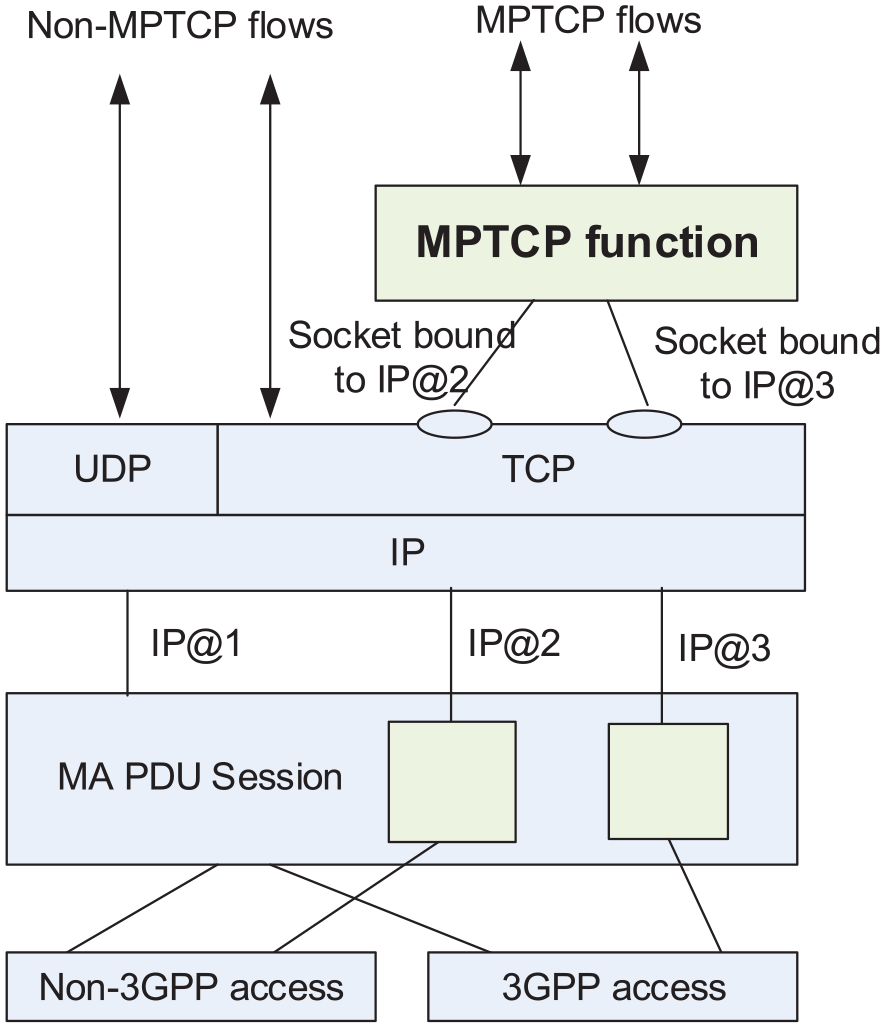
Example of UE supporting the MPTCP function with separate addresses.
Consequently, MPTCP requires an IP address for each subflow and ATSSS uses an IP address for each MA PDU session. As the IP address allocation unit is different between MPTCP and ATSSS, it is difficult to reuse the IP address allocated to the PDU session for MPTCP. Due to this address allocation and management problem, the number of IP addresses that must be managed in the network increases with the number of UE that uses MPTCP. The frequent allocation of IP addresses in the network can generate signaling overhead. If the SMF allocates IP addresses for MPTCP for each access, management tasks such as resource setting and release for each access become complex.
In addition to the problem of the 5G network architecture and IP address management in applying the on-path MPTCP proxy model for providing the ATSSS function in the 5G network, another major issue is the forwarding rule, which is required for the UPF to perform the steering of the MPTCP subflows to a multi-access network. This requirement did not exist in the off-path proxy deployment in LTE. It is indispensable for the MPTCP proxy to distinguish the routing path for each access in 5G ATSSS, where a proxy exists on a common routing path. Furthermore, to selectively control MPTCP traffic steering by considering ATSSS functionality (MPTCP, ATSSS-LL) information, an extended N4 rule is required, including the ATSSS forwarding rule between the SMF and UPF. It is impossible to control the MPTCP subflows with the existing N4 rule (packet detection rules, forwarding rules) based on Release 15, which does not consider multi-access networks.
Another issue that must be considered in 3GPP ATSSS is to support the “steering mode,” which determines the method by which application traffic is distributed between 3GPP and non-3GPP accesses. The current MPTCP can split one application data stream into one or more subflows by default 18 and supports the operation of MPTCP subflow in normal or backup modes. 31 Hence, if the transmission state of the normal subflow becomes poor, it can be handed over to a backup subflow. 32 However, 3GPP ATSSS requires more steering modes. 22 In the “active-standby” steering mode, application traffic can be switched to standby access if active access is unavailable. In the “smallest delay” mode, the application traffic must be steered to the access with the smallest round trip time (RTT). In addition, “load balancing” and “priority-based” steering modes are defined. The steering modes supported by the current MPTCP have limitations in satisfying the ATSSS requirements. Therefore, these modes must be extended.
Table 1 outlines the problems that must be solved to support the ATSSS function using MPTCP in 5G networks and the solutions according to design requirements. To satisfy the architectural characteristics of 5GS and the ATSSS requirements, this table presents the problems caused by the limitations of the current MPTCP and 5GS based on Release 15 and the design requirements to overcome them. The problems are solved by presenting the design directions for address management, the extension of the N4 rule for traffic control in a multi-access network, and the support for additional ATSSS steering modes based on the on-path MPTCP proxy model.
Problems and design requirements to support ATSSS in 5GS.

MPTCP: multipath transmission control protocol; UPF: user plane function; MATS: multi-access traffic steering; PDU: packet data unit; UE: user equipment; ATSSS: access traffic steering, switching, and splitting; 5GS: 5G System; FAR: forwarding action rule.
Proposed design for MATS with MPTCP proxy model
The design for implementing the ATSSS function of the 5G network using MPTCP must allow for the use of multiple network paths through MPTCP subflows even in a single TCP connection between the terminal and server, which is the basic design goal of MPTCP, and satisfy the requirements for providing the ATSSS service according to the 5GS design principles. Therefore, this article proposes an MPTCP-based MATS solution that satisfies the design requirements listed in Table 1 to provide the ATSSS function in 5GS.
According to the design requirements for the ATSSS function, in an architecture that accommodates the multi-access network within the 5G network, it is most rational to apply the on-path proxy model in which the MPTCP proxy exists in the UPF for distributed traffic transmission to the multi-access network. Figure 4 shows the ATSSS architecture in which the MPTCP proxy is within the UPF. In the proposed MPTCP-based MATS model, the MPTCP client and MPTCP proxy functions exist in the UE and UPF, respectively, which directly process traffic transmission and reception through a multi-access network. The UE consists of an ATSSS rule(s) to transmit uplink MPTCP traffic, and the UPF requires a packet detection rule(s) (PDR) to transmit downlink MPTCP traffic. The ATSSS rule and PDR are created based on the policy and charging control (PCC) rule(s) delivered from the PCF. These additional rules are generated by the SMF and delivered to the UE and UPF, which can perform access traffic steering for each application based on the ATSSS rule(s) and PDR(s), respectively. Thus, the PCF and SMF must to be extended to control traffic steering in each MA PDU session in addition to the UE and UPF.
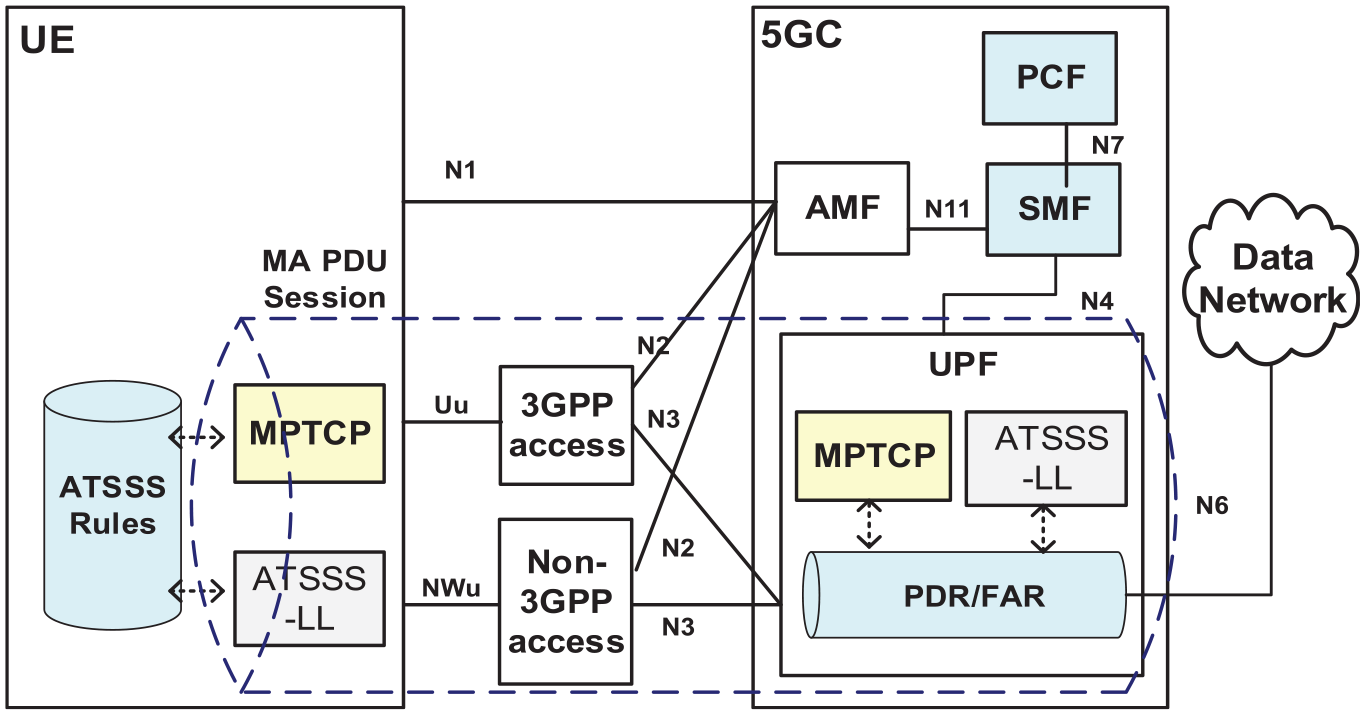
ATSSS architecture including MPTCP proxy within UPF.
Next, as discussed in the previous section, the UE with the MPTCP functionality must have a minimum of three addresses allocated for each MA PDU session and an MPTCP proxy address. In 5GS, an exclusive address for each subflow for MPTCP must be allocated in addition to one IP address for each PDU session of the UE, and an address for the MPTCP proxy server must also be allocated. An MPTCP proxy address management mechanism is proposed for the MPTCP-based MATS solution to provide the efficient ATSSS function in the 5G network. This mechanism can simplify the UE functions and reduce the number of required IP addresses. An MPTCP proxy address is allocated for each access instead of adding an address of the UE (strictly speaking, multiple PDU sessions generated per UE) for each subflow for the MPTCP functionality. In other words, a proxy IP address for each access is used instead of allocating a UE IP address for each access for MPTCP in each PDU session in the 5G UE. In this case, the UE can use one IP address for each PDU session without distinguishing it as a separate MPTCP address, and the UE can share the proxy IP addresses for MPTCP. When the UE IP address is used, the number of required IP addresses increases with the number of UE that use the MPTCP function. However, the advantage of using the proxy IP addresses is that a fixed number of proxy addresses (two addresses for 3GPP and non-3GPP accesses) is required according to ANs, regardless of the number of UEs.
Figure 5 shows the MPTCP connection and subflow setting process with the proposed address management mechanism. Assuming that N UEs have one MA PDU session and generate two MPTCP subflows, there are N times the three minimum addresses allocated per UE, and a proxy IP address is additionally required. Thus, 3N + 1 addresses are required in total. However, with the proposed method of using the proxy IP address (B1, B2), only N UE IP addresses and two proxy IP addresses are required. Thus, only N + 2 addresses are required in total. Consequently, no additional overhead for signaling and address management is generated because the total number of IP addresses is reduced and the additional process for allocating IP addresses to UE is not necessary.

Initialization of MPTCP connection and generation of new subflow between UE and MPTCP proxy with proposed address allocation mechanism.
One remaining issue is that the N4 rule for the UPF must be extended to transmit traffic in multiple access environments and to provide the steering modes required by ATSSS. In particular, the provision of additional steering modes assumes the existence of the MPTCP proxy within the UPF because it must be carried out when traffic steering is performed in the UPF. Currently, in 3GPP Release 15, a PDR and a forwarding action rule (FAR) are created through the N4 interface based on the SA PDU session. Hence, this study designed the N4 rule to include steering functionality and steering mode information with logical connectivity with the existing N4 rules by utilizing the multi-access rule (MAR) 22 to support the MA PDU session. Table 2 lists the components of the MAR. Per-access forwarding action information (PAFAI) is defined so that the MAR can map multiple FARs, which include the forwarding information for SA. Unlike 3GPP ATSSS, whose accesses are limited to 3GPP and non-3GPP, adding the PAFAI to one MA PDU session provides the traffic steering function with unlimited ANs.
Attributes within multi-access rule.

MPTCP: multipath transmission control protocol; ATSSS: access traffic steering, switching, and splitting.
The proposed MPTCP-based MATS system satisfies the ATSSS requirements by enhancing the UE, UPF, PCF, and SMF functions and can be extended to provide traffic steering among multiple accesses by overcoming the constraints of the standard that provides traffic steering between 3GPP and non-3GPP accesses to accommodate the MPTCP functionality in 5GS. In the following section, the essential functional elements of the MATS system and their functions are briefly explained.
UE-MPTCP client
Figure 6 shows the structure of the UE in the MPTCP-based MATS system to which the address management mechanism based on the proposed MPTCP proxy has been applied. The UE largely consists of an MPTCP client, packet forwarding to the multiple accesses of the MA PDU session (MAPS), and a non-access stratum (NAS) control module for receiving and managing the ATSSS rule. The functional modules that are not directly related to this study are omitted.

UE structure supporting ATSSS function combined with the MPTCP protocol over MA PDU sessions with NAS control.
The main functions of the UE are as follows: the MPTCP function receives the MPTCP proxy address for accessing MPTCP through the multiple accesses in the UE from the NAS control module, performs socket binding for the address, and exchanges packets with applications through this socket. As the MPTCP proxy address for the access type is also received from the NAS control module, the subflow can be generated by utilizing the proxy address for each access. The MAPS packet forwarding function manages routing with actual access according to the MPTCP proxy address and the connection status of the corresponding AN. In addition, it notifies the changed state of the actual AN to the MPTCP function through the NAS control module. The NAS control module for the ATSSS rule control forwards the MPTCP proxy address and ATSSS rule information received from the CN to the MPTCP function and MAPS packet forwarding function modules and informs the session setting state through a graphical user interface (GUI) function. Note that the UE’s address and MPTCP proxy address are received from the CN (SMF and UPF) through the PDU session establishment NAS procedure between the 5G UE and CN. Therefore, the ATSSS control function either can exist between the existing NAS control module and MPTCP function or can be included in the NAS control module. In this study, the ATSSS control function is designed and implemented to be included in the NAS control module.
UPF–MPTCP proxy
Figure 7 shows the UPF structure that includes the MPTCP proxy function. To support the ATSSS function, the UPF is composed of the MPTCP proxy function module, ATSSS N4 rule control module, and MAPS packet forwarding module. The major functions of each module are as follows: the ATSSS N4 rule control module is added for the ATSSS function in addition to the N4 forwarding rule between the SMF and UPF. The ATSSS N4 rule control module controls packets with newly defined MAR information while maintaining connectivity with the PDR and FAR. It can be configured separately or included in the existing N4 rule control function. In this work, it is included in the existing N4 rule control function for the convenience of implementation because it is closely correlated with the existing PDR and FAR. The MPTCP proxy function distributes and combines packets. For this purpose, it exchanges control messages with the N4 rule control module and exchanges traffic with the MAPS packet forwarding module. For the ATSSS function, the MAPS packet forwarding module generates the MAR with the information received from the N4 rule control module and processes MPTCP traffic along with the MPTCP proxy function module based on the MAR.

UPF structure supporting ATSSS function combined with the MPTCP proxy over MA PDU sessions.
Figure 8 shows the packet processing flow in the UPF when the MAR is applied for ATSSS in the proposed MPTCP-based MATS system. After looking up the PDR in one N4 session, the UPF selectively applies either the FAR for SA or the MAR for multi-accesses, and the MAR processes packets with the FAR for each access. The steering functionality is selected depending on the content of the MAR, and traffic processing is applied in accordance with the specific steering mode.

Packet processing flow in the UPF for ATSSS.
SMF and PCF–PCC rule for ATSSS
The SMF and PCF do not directly process packets like the UE and UPF in providing the ATSSS function using MPTCP in 5GS. However, they are indispensable for packet distribution control in 5GS and can be considered as a kind of control modules of ATSSS. To apply the traffic distribution function of MPTCP to 5GS, the SMF creates and manages an MA PDU session, which is an access traffic management unit, and generates a forwarding rule (MAR) based on the PCC rule to allow for the distributed transmission of MPTCP traffic in the MA PDU session for each AN. Then, the SMF performs controls to apply the steering functionality and steering mode to the traffic according to the MAR information when the UPF performs traffic steering.
The major correlations between the UE and UPF that perform traffic steering and ATSSS control through the PCF and SMF are as follows: when an MA PDU session is set between the UE and CN, the SMF receives the PCC rule from the PCF and newly generates the ATSSS rule and N4 forwarding rule for each application based on the PCC rule. The ATSSS rule is sent to the terminal and used for uplink traffic steering, and the N4 forwarding rule is sent to the UPF and used for downlink traffic steering.
Testbed system implementation
A testbed was established and experiments conducted to verify the efficacy of the proposed MPTCP-based MATS system. This section presents the simple testbed experimental environment and actual experimental results.
Testbed network configuration
The testbed environment is largely composed of the UE, AN (5G NR, WiFi, fixed), CN (UPF, access and mobility management function (AMF), SMF, PCF, etc.), and application server, as shown in Figure 9. As there is a limit to the configuration of the 5G RAN in the testbed environment, the 5G RAN is configured by emulating the LTE RAN based on software-defined radio (SDR).

Testbed for MPTCP-based MATS system.
The UE is connected to the 5G RAN through the SDR, to the WLAN through the AP, and to the wired AN through Ethernet on a high-speed laptop using the Ubuntu 14.04 LTS operating system. The functional elements of the control plane of AN and CN are composed of a server based on the Ubuntu 14.04 LTS. The UPF of the user plane, which is the MPTCP proxy, uses the CentOS 7.1.1503 operating system, and it is processed in a separate network processor card for the high-speed processing of bulk data. In addition, the default settings are used for the congestion control and scheduler of the MPTCP because they are not directly related to the test performed in this work.
Experimental scenario and results
This section briefly describes the result of the traffic test based on actual multimedia application on the proposed MPTCP-based MATS system. The MPTCP-based MATS system is verified by employing the configured testbed. The test is performed with a streaming service for multiple videos. Table 3 outlines the information of the test videos.
Test video information.

AVC: advanced video coding; AAC: advanced audio coding.
Figure 10 shows the screenshots of the UE GUI used in this test, the operations, administration, and maintenance (OAM) screen for the progress, and a monitoring tool for checking traffic distribution through multi-accesses. The UE GUI is composed of an application at the top, multiple accesses in the middle, and a bar indicating the PDU session at the bottom. The OAM screen shows the UE, AN, CN, and application server at a glance. It also shows the sequence chart of control signaling messages. The “NetData” monitoring tool is installed in the UE, and it enables us to monitor the traffic transmission and reception rates for each interface. Numbers ① to ③ indicate the performance steps in the terminal and the corresponding screens displayed in the OAM and NetData.
(a) UE, (b) OAM, and (c) NetData screenshots of MATS testbed system.
In the UE screen shown in Figure 10(a), the MA PDU session is connected to one PDU session through the 5G RAN access between the UE and network (①). The screen indicates that the video streaming application is running in the established session (②). The left part shows the image of the played video (Figure 10(a)). Similarly, the OAM screen also shows that the traffic of the video streaming application is transmitted only by the 5G RAN in the MA PDU session generated through the 5G RAN access (Figure 10(b)). Finally, the traffic measurement monitoring for each interface of NetData confirms that up/down traffic is transmitted only over the 5G RAN (Figure 10(c)).
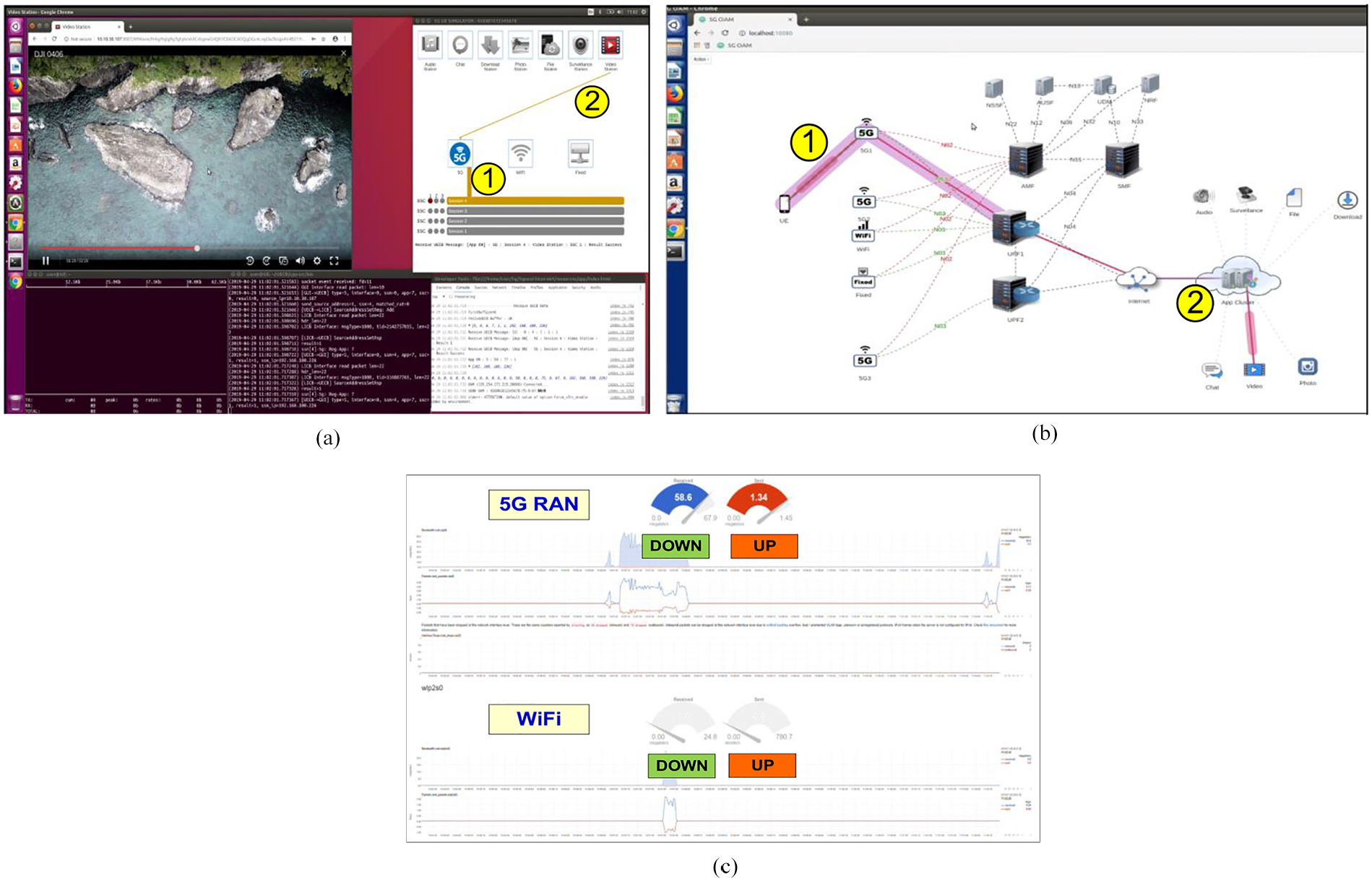
If additional access (WiFi in the test) is made available during the traffic transmission for MPTCP-based traffic splitting, the traffic transmitted only through the 5G RAN is split into two accesses, that is, 5G RAN and WiFi, as shown in Figure 11. As a result, the UE can receive services with no interruption.

(a) UE, (b) OAM, and (c) NetData screenshots of MATS testbed system.
Figure 11(a) shows a screen in which the WiFi access of the MA PDU session has been added in Figure 10(a) (3). The information about the availability of the WiFi AN is sent from the UE to the network. Then, the traffic transmission to the added access is split and traffic is distributed to the 5G RAN and WiFi AN. The WiFi access of the MA PDU session is also added to the OAM, and traffic is transmitted through the 5G RAN and WiFi AN (Figure 11(b)). Similarly, the traffic measurement monitoring for each interface of NetData also confirms that up/down traffic is distributed through the 5G RAN and WiFi AN (Figure 11(c)). Note that different speed units for up/down traffic appear in the figure according to the amount of transmission data because the NetData monitoring tool automatically adjusts the speed unit of up/down graphs, such as megabits/second or kilobits/second, to increase readability.
Throughput analysis
In this section, we analyze the throughput of MPTCP to demonstrate its performance under various network conditions. We derive a simple model based on the throughput model proposed by Padhye et al. 33 and Chen et al. 34 In the analysis, we assume that packet loss events are uniformly distributed and TCP is in the steady state in networks with large bandwidth. We consider only the packet loss caused by triple duplicate ACK because packets are rarely lost.
Let p be the probability that the first packet in a round is lost or packet loss occurs in a round without the preceding packet loss. If the αth packet is lost in a round, α is calculated in Padhye et al. 33 as follows

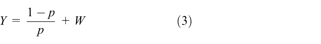
When the αth packet is lost, if the congestion window is W, W – 1 packets are transmitted after the packet loss. Therefore, the total number of packets transmitted between two triple duplicate ACK events, Y, is

From equations (1) and (2), Y is rewritten as
Let X be the round where the αth packet loss occurs. The congestion window starts from W/2, increases by one in every round, and it is W at round X. Then, W is calculated by

We neglect the constant terms because we assume large bandwidth. Therefore, W is simplified as follows
From equation (4), X is simply calculated by

Y is calculated by adding the number of packets transmitted in each round. Then Y is expressed by
where β is the number of packets transmitted in the last round. Because β is uniformly distributed between one and W – 1, β is calculated by

From equations (4), (7), and (8), Y is calculated as follows

From equations (3) and (9), W is calculated by
We define A as the duration between two events of triple duplicate ACK, and it contains X+1 rounds as follows

From equations (3), (10), and (11), the throughput, B, can be calculated by

where k is the packet size.
MPTCP utilizes several links simultaneously for performance enhancement. We define

where
When n links are utilized, the aggregate throughput,

In the throughput analysis, we assume that MPTCP uses two links, one fast and the other slow. We use two load balancing modes: dynamic and static. As the amount of transmitted traffic is inversely proportional to the RTT in the dynamic mode used in MPTCP, the fast link transmits more traffic than the slow link, and then two transmissions are completed almost simultaneously. An administrator determines the amount of traffic for each link in static mode, similar to the load-balancing steering mode in ATSSS. In this analysis, we assume that the ratio of transmission traffic is 50:50 in static mode. We vary the RTT for various network conditions. In the study by Langley et al., 35 the RTTs in good, average, and bad network conditions are 38, 50, and 188 ms, respectively. We consider three network conditions in Table 4, and the aggregate throughput is calculated using equation (14). Figure 12 shows analysis results with different packet loss rates in the three network conditions. The x-axis and y-axis represent the packet loss probability and throughput, respectively. As the packet loss rate decreases, the aggregate throughput increases. As shown in the figure, the throughput in dynamic mode is higher than that in static mode because dynamic mode adjusts transmission traffic based on the RTT to complete both transmissions simultaneously. If the difference between the fast link and the slow link is small, the two modes show similar throughput, as shown in Figure 12(a). However, the difference in throughput between the two modes increases as the difference between the fast and slow links increases, as shown in Figure 12(b) and (c). The transmission time in static mode depends on the slow link because the transmission traffic ratio is the same; thus, the throughputs are the same regardless of the fast link. Compared to static mode, dynamic mode shows better throughput performance based on the RTT under the various network conditions. Meanwhile, the throughput of static mode depends on the slow link because the ratio of the transmission traffic is determined by the administrator. Similarly, the ratio of the traffic is determined based on the policy from the PCF in the load-balancing steering mode of ATSSS. In that case, the policy may be updated according to the network condition to improve the performance of the throughput, although the policy for the ATSSS is created by an operator based on the UE’s information. Therefore, MPTCP should support static mode for the ATSSS in addition to dynamic mode.
Network conditions for throughput analysis.

RTT: round trip time.

Throughput analysis under (a) good and average conditions, (b) average and bad conditions, and (c) good and bad conditions.
Conclusion
The 5GS architecture comprises a common core with a single interface to minimize AN–CN dependency and to accommodate various types of ANs related to each service while requiring support for various types of multimedia services. In this architecture, access traffic steering functions are required more than access traffic aggregation. 22 This article proposed an MPTCP-based MATS solution to satisfy these requirements. The proposed MATS solution consists of a model that can apply MPTCP in accordance with the design philosophy of the 5G network architecture and designed 5G extensions to satisfy the 3GPP ATSSS requirements. In applying the on-path MPTCP proxy model, the following problems were caused by the architecture of 5GS: concentration of MPTCP subflows in the UPF and distribution to the AN; requirement for multiple additional IP addresses for MPTCP in each UE. To solve these problems, an MPTCP-based MATS system minimized the overhead of the signaling and control of 5GS while using a minimal number of IP addresses. A testbed for the proposed MATS system was implemented based on 3GPP Release 15, and the appropriate operation of access traffic steering was verified by actual multimedia data transmission.
The proposed MPTCP-based MATS system can be easily implemented in 5GS. It can expand the bandwidth of services and is applicable to various steering services according to the steering mode. Furthermore, the proposed system can immediately accommodate new ANs and can be extended with no limit to the number of ANs. However, the optimal number of ANs and the performance of the proposed system in various network multimedia-centric environments must be verified in future studies.
Footnotes
Handling Editor: Partha Roy
Declaration of conflicting interests
The author(s) declared no potential conflicts of interest with respect to the research, authorship, and/or publication of this article.
Funding
The author(s) disclosed receipt of the following financial support for the research, authorship, and/or publication of this article: This work was supported by the Institute of Information & Communications Technology Planning & Evaluation grant funded by the Korea government (MSIT) (no. 2015-0-00042-005, Development of Wired-Wireless Converged 5G Core Technologies) and by the National Research Foundation of Korea (NRF) grant funded by the Korea government(MSIT) (no. 2018R1C1B6008187).