
Abstract
In this article, we address dynamic workflow management for sampling and filtering data streams in Apache Storm. As many sensors generate data streams continuously, we often use sampling to choose some representative data or filtering to remove unnecessary data. Apache Storm is a real-time distributed processing platform suitable for handling large data streams. Storm, however, must stop the entire work when it changes the input data structure or processing algorithm as it needs to modify, redistribute, and restart the programs. In addition, for effective data processing, we often use Storm with Kafka and databases, but it is difficult to use these platforms in an integrated manner. In this article, we derive the problems when applying sampling and filtering algorithms to Storm and propose a dynamic workflow management model that solves these problems. First, we present the concept of a plan consisting of input, processing, and output modules of a data stream. Second, we propose Storm Plan Manager, which can operate Storm, Kafka, and database as a single integrated system. Storm Plan Manager is an integrated workflow manager that dynamically controls sampling and filtering of data streams through plans. Third, as a key feature, Storm Plan Manager provides a Web client interface to visually create, execute, and monitor plans. In this article, we show the usefulness of the proposed Storm Plan Manager by presenting its design, implementation, and experimental results in order.
Introduction
In recent years, many emerging applications of SNS, finance, sensors, and IoT (Internet of things) rapidly generate huge volumes of data streams. 1 Data streams are constantly and continuously generated, and storing all such data streams is very difficult in terms of storage capacity. Also, using the entire data stream for analysis is very inefficient in terms of processing speed. Thus, we often use sampling and/or filtering for choosing the representative data and/or extracting the necessary data from the data stream.2,3 Sampling and filtering not only reduce the size of a large data stream, but also extract only meaningful data necessary for the user, and thus, they are very important in the process of preprocessing the data stream. As the speed and amount of data streams increase, however, there is a limitation in processing sampling and filtering in a single server.
To handle big data 4 that is constantly generated very fast, there have been many recent efforts on processing data streams in the distributed environment. Representative distributed platforms for processing data streams include Apache Storm5,6 and Apache Spark Streaming. 7 In particular, Apache Storm is a distributed processing platform that efficiently analyzes a huge amount of data streams in distributed servers in real time. In general, this distributed processing platform is used with a separate queuing system for input and output of data streams. Apache Kafka8,9 is a distributed message queuing system that is often used as input, output, or pipeline for the data stream processing platform such as Storm and Spark Streaming. 10 To fully exploit these distributed systems, we need an efficient and convenient workflow manager. Typical workflow managers for distributed systems include Apache Oozie, 11 Apache Airflow, 12 and WSO2 Stream Processor. 13 However, the only workflow manager for Strom is StreamFlow, 14 which provides only limited services and even stops updating its services. Based on this observation, in this article, we propose an efficient and convenient workflow manager for Apache Strom.
In this article, we propose SPMgr (Storm Plan Manager; all source codes and demonstration video of SPMgr are available at https://github.com/0KUK/PlanManager/), an integrated workflow manager that can dynamically manage sampling and filtering functions based on Apache Storm. For this, we first derive two problems of low availability and no integration, which occur when simply applying sampling and filtering algorithms to the existing Storm. First, low availability is a problem that some data may be lost if sampling or filtering features change. As Storm defines collection and processing modules together, we need to modify and redistribute the source codes whenever we want to change data structures or processing algorithms. In this procedure, some data streams may be lost until the process is restarted. Second, no-integration is a problem that big data platforms such as Storm, Kafka, and database are separately managed by each management function even if they are used for one purpose. This separate management is because those open platforms are developed for different purposes.
To solve these two problems, the proposed SPMgr presents two solutions: module separation and platform integration. First, module separation is the concept of separating data collection and storage modules from the processing module of Storm, achieving high availability. Through this separation, even if we restart the processing module due to the change of the algorithm, data collection and storage modules can continuously operate. To achieve this, we present the concept of a plan that defines how to combine input, processing, and output modules of data streams. Second, platform integration is the concept of integrating Storm, Kafka, and database as a single interface, and based on this integration, we propose SPMgr, a dynamic workflow manager. In other words, we can manage all the functions using SPMgr without having to perform management tasks for each platform. In addition, SPMgr provides a Web UI (Web User Interface), which allows the user to visually create, modify, delete, and monitor plans through the user-friendly interface.
In this article, we provide the design and implementation results of SPMgr. We first describe the detailed design of database tables and software components to show design characteristics of SPMgr. We then present the implemented user interfaces to show how SPMgr works in the real environment. We also present the actual sampling and filtering results to show the practical use of SPMgr. With these advantages of SPMgr, we can easily use sampling and filtering capabilities for big data streams in a Storm-based distributed environment.
The rest of the article is organized as follows. Section “Background” describes the background of this work. We first explain sampling and filtering algorithms implemented in SPMgr. We then explain open source distributed processing platforms, Apache Storm and Apache Kafka, respectively. In Section “Problems and their solutions,” we derive the problems of simply applying sampling and filtering to Storm. Section “SPMgr: Storm Plan Manager” describes the detailed design of the proposed dynamic workflow manager, SPMgr. Section “Implementation and evaluation” explains the implemented SPMgr with actual user interfaces and presents sampling and filtering results by SPMgr. Section “Related work” explains StreamFlow 14 and WSO2 Stream Processor, 13 a Storm-based workflow manager, as a related study. Finally, Section “Conclusion” summarizes and concludes the article.
Background
The proposed SPMgr addresses an efficient solution for sampling and filtering algorithms in Apache Storm. Thus, this section explains the sampling and filtering algorithms supported by SPMgr, and introduces Apache Storm and Apache Kafka used for distributed processing.
Sampling and filtering algorithms
Sampling is a statistical technique that extracts some of the data representing the population. Sampling algorithms can be divided into batch-specific sampling and data stream–specific sampling. 15 First, batch-specific sampling includes systematic sampling, stratified sampling, and cluster sampling. 16 Next, data stream–specific sampling includes reservoir sampling, hash sampling, K sampling, priority sampling, and binary Bernoulli sampling.17–21 Brief explanation on extracting samples by each method is as follows.
Systematic sampling randomly selects the first entry, and then selects the kth entry every time.
Stratified sampling divides the population into nonoverlapping layers, and then extracts samples from each layer.
Cluster sampling divides the population into several subclusters, and then selects some subclusters as samples.
Reservoir sampling selects the first k samples of the data stream, and probabilistically replaces those previous samples using the subsequent input stream.
Priority sampling works similar to reservoir sampling, but priorities are assigned according to the frequency of data occurrence. That is, the more frequent data, the more selected.
Hash sampling applies a hash function to a specific field of data records, and selects a record as a sample if its hash value is greater than (or smaller than) the specified value.
K sampling 22 is a random sampling method that dynamically increases the sample size to keep the sampling rate constant for the input data stream.
Binary Bernoulli sampling 23 extracts samples at the same probability when data streams come from multiple sources.
Filtering is a technique for extracting only data satisfying a given condition to improve data quality or analysis speed. 24 Representative examples include query filtering 25 to extract only data satisfying the given query, bloom filtering 16 to stochastically calculate whether the data belong to the set, and Kalman filtering26,27 to estimate the original data from the data containing errors such as sensor data. There are two major categories of applying these filtering techniques to the data stream. First, the standing queries method evaluates the predefined query condition for the input data, and stores or passes the data when the condition is satisfied. Second, the ad hoc method stores input data for a predetermined time or size and evaluates the query on the stored data.
Real-time distributed processing platforms
Apache Storm
As a representative distributed processing system, Apache Storm5,6 processes data streams in real time. Storm uses a topology to define a series of tasks from input to output of data, and the topology consists of multiple spouts and bolts. Figure 1 shows the operation procedure of Storm. First, a spout replaces the data received from the source of the data stream with tuples, the data type of Storm, and passes the tuples to a bolt. A spout generally does not implement a processing logic itself, so we can use it commonly in various topologies. Storm also provides an API to import data from Twitter or Apache Kafka. Next, a bolt processes the tuple received from the spout or bolt and passes the result to the next bolt, or sends the result to the output or storage device. As the Storm topology defines the collection and processing functions together, we need to stop the entire work if the input data structures or processing algorithms change. In other words, if the change is necessary, we need to modify the source code, build a new topology, and redistribute the topology, resulting in a long-term service interruption.

Data stream processing procedure of Apache Storm.
A Storm cluster consists of one Nimbus node, multiple Supervisor nodes, and multiple Apache Zookeeper nodes as shown in Figure 2. First, the main function of Nimbus is to manage the topology running in the cluster. It also deploys the topology into the cluster and then assigns the work unit to the topology. Deploying a topology in a Storm cluster means submitting the packaged JAR file topology to the Nimbus server. Second, Supervisor is the Worker node that actually performs the task, and the work unit is assigned from Nimbus. It then creates and monitors the Workers that run the work unit. A Worker is actually a Java process that runs spouts and bolts. Third, Zookeeper is a distributed coordinator for monitoring the status of cluster nodes and managing the shared information. Through Zookeeper, Storm monitors the node status, shares the work status, and provides a fault-tolerant function.

Physical architecture of Apache Storm.
Apache Kafka
As a typical distributed message queuing system, Apache Kafka8,9 is often used for real-time processing of large log data. Kafka has a typical distributed architecture, making it very easy to scale up and speed up the system. In addition, it ensures high data reliability by storing data on disk, not memory, and performs message queue role and data collector role together.
As shown in Figure 3, Kafka is based on the publish-subscribe model and consists largely of producer, consumer, and broker. The producer publishes messages issued from other systems to the broker, and the consumer subscribes to messages issued from brokers on other systems. At this time, the broker means a node in which Kafka is installed, and it stores the messages by topics. A topic is a concept of logically classifying messages, and they are divided into partition units and stored in brokers. Figure 4 shows how Kafka divides the topic into partitions to store data. Partitions manage the offsets to ensure the order of the input data, and for new input data, store the new data at the most recent offset.

Publish-subscribe model of Apache Kafka.

Topic partitioning in Apache Kafka.
Problems and their solutions
In this section, we first describe the problems when applying sampling and filtering algorithms to Apache Storm. We then present two design techniques to solve the problems. There are two problems in processing the existing sampling and filtering algorithms in Storm.
Low availability: Storm defines data collection and processing together, so service disruption may occur when data structures or processing algorithms change. Even a small change may lead to the modification of the source codes and the restart of entire processes. Thus, some portion of the data stream may be lost until the processes are normally restarted.
No integration: Data processing platforms are developed for their own different purposes, so they lack integrated management features. Storm is specialized for data stream processing, so we generally use Storm with Kafka for queuing function and a database for data storage. Also, if we want to operate various platforms, we need to use different commands and parameters in each platform. This individual management approach is not only difficult to use, but also easy to incur mistakes, so we need an integrated management approach across multiple platforms.
To solve the above two problems, in this article, we propose the following two solutions.
First, we propose module separation to solve the low-availability problem. Module separation is to separate data stream collection, processing, and storage modules independently. With this separation, each module can operate independently without being affected by the operation of the other modules. For example, even if a processing module is out-of-service, the collection module can continuously collect the data stream and pass it to the other processing modules. Also, even if an input module is out-of-service, the processing module can continue to handle the existing or other input streams. Thus, through the module separation, we can improve the service availability of Storm.
Second, we propose platform integration to solve the no-integration problem. Platform integration is an integrated management function for the three platforms of collecting, processing, and storing data streams. With this integrated management, we can use Storm, Kafka, and database like a single system. In addition, we provide users with an integrated Web UI to manage all three platforms at once. Thus, through this platform integration, we can manage a Storm-based sampling and filtering system in an integrated manner.
In this article, we design and implement SPMgr, a Storm-based data stream sampling and filtering system that supports the above two design requirements.
SPMgr: Storm Plan Manager
In this section, we describe SPMgr, the proposed Storm-based workflow manager. First, SPMgr has a client-server model structure as shown in Figure 5. The client server architecture is a most widely used analytical management model and has an advantage of being easy to maintain multiple users at the same time. In particular, we implement the client as a Web-based system, allowing users to easily access SPMgr anytime and anywhere via a Web browser. The Web client provides user authentication, plan creation, and plan monitoring functions. The proposed SPMgr provides several sampling and filtering algorithms in this Storm-based client-server architecture.

Overall architecture of SPMgr.
Next, we design SPMgr to satisfy the two requirements, module separation and platform integration, presented in “Problems and their solutions” section. First, to satisfy the module separation, we propose a plan model and thereby increase the availability of data stream collection and processing. Here, the plan model is an integrated management model, which increases the independence of the input, processing, and output modules and at the same time integrates multiple different management functions. Second, to satisfy the platform integration, we implement the RPC interface and related handlers. The RPC interface delivers commands between the Web client and Storm, Kafka, and the database, allowing those multiple platforms to operate as a single system. More specifically, the RPC interface gets JSON-style user commands from the Web client and classifies the command types, and then, according to the command type, it calls a plan handler, a source handler, and a destination handler to perform algorithm execution, source management, and destination management, respectively. Subsection “Plan” details the plan, which is a logical flow of processing the data stream. Subsection “Web Client” presents the function of the Web client and the related table structures. Subsection “RPC Interface and Handlers” describes the RPC interface and related handlers that perform the actual plan.
Plan
The plan is a unit of work definition in SPMgr, and it consists of three modules, source, topology, and destination, as shown in Figure 6. First, the source manages the information and schema of the input data stream and reads the data from the specified source. Second, the topology processes storm-based sampling and filtering algorithms. Table 1 shows the sampling and filtering algorithms implemented in SPMgr. Hash sampling, priority sampling, reservoir sampling, systematic sampling, bloom filtering, and query filtering are relatively simple and can be implemented directly in the distributed environment. However, the complicated algorithms such as K sampling, 22 binary Bernoulli sampling, 23 and Kalman filtering 26 are difficult to be implemented in the distributed environment. We have already provided their distributed solutions in previous studies. Thus, for the scalability issue of distributed algorithms, readers are referred to such previous studies.22,23,26 Third, the destination manages the repository information for the data extracted by the topology, and outputs the data stream to the external repository.

Conceptual structure of a plan in SPMgr.
Sampling and filtering algorithms provided by SPMgr.

Using the plan model, we can configure and operate the source (i.e. input), topology (i.e. processing), and destination (i.e. output) independently, satisfying the requirement of module separation. More specifically, a plan consists of one source, one destination, and one or more topologies. Each module operates independently, and sends and receives data streams through Kafka. Kafka temporarily stores the intermediate data processed by each module of the plan, but SPMgr does not provide the intermediate data to the user to minimize the latency caused by unnecessary network communications. However, the user who wants to use the intermediate data directly can transfer the data to the user’s local repository by dividing a long plan into a series of small plans. In this case, we can store and use the intermediate data by connecting the destination of the previous plan to the source of the next plan. An operation example of a plan is as follows. First, the source collects the data stream and stores the data in topic A of Kafka. Next, the topology reads the data stream of topic A, performs sampling and/or filtering, and stores the result in topic B. Finally, the destination reads topic B and outputs the result to the external storage. In this example, we can see that source, topology, and destination modules work independently, and the interruption of a particular module does not affect other modules, so using a plan model we can provide higher availability. In addition, we can change the sampling and filtering topology, while the source collects the input data, or the destination outputs the result, enabling dynamic workflow management.
Web client
Through the plan concept, we separate input, processing, and output functions, but using the Web client, we can manage these functions in an integrated manner. In other words, we implement the client of SPMgr as a Web-based interface so as to allow users exploiting all the functions of input, processing, and output modules easily through the Web browser. The Web client provides users the Web UI so as to visually manage their plans. The Web UI consists of the user authentication phase, the source menu, the destination menu, and the plan menu, and we describe these interfaces in detail in this section.
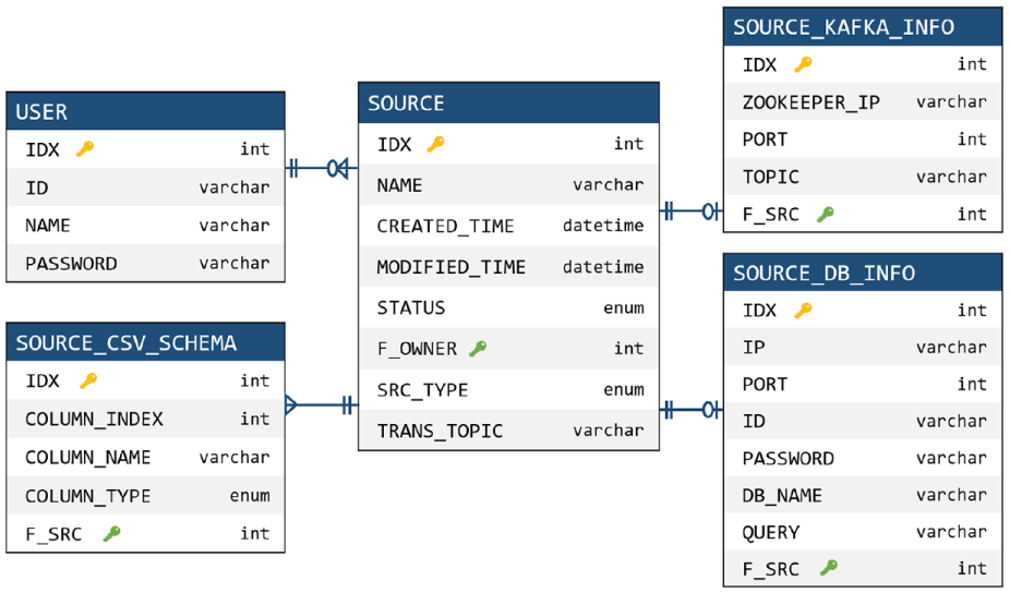
In the user authentication phase, we can use account creation and login functions. For user authentication, SPMgr manages the user information table in the database as shown in Figure 7. Users can log in to their accounts, and after logging in, they can use the plan, source, and destination menus.

User information table managed in the database.
In the source menu, we can see the source names, creation and modification dates, and execution status. The source types provided by SPMgr include Kafka, database, and customizing source. If the source type is Kafka, SPMgr manages Zookeeper IP and port of the Kafka cluster, and the topics to read. If the type is the database, SPMgr manages the IP, port, ID, password, and name of the database. It also provides a customizing source that can be designed by the user. Using this customizing source, the user can input data directly into Kafka through a Java interface. In addition, in the source configuration phase, we need to specify the schema of the input data. To do this, SPMgr manages the name and type of the data column, and supports three data types: TEXT, NUMERIC, and DATE. Figure 8 shows the tables and relationships that manage the source information described so far.
Source information tables and relationships managed in the database.
In the destination menu, we can see the destination names, creation and modification dates, and execution status. Like the source type, it provides Kafka, database, and customizing destination as the destination type. We manage such destination information in the tables and relationships of the database as shown in Figure 9.

Destination information tables and relationships managed in the database.
In the plan menu, we can see the plan names, creation and modification dates, and execution status. We configure a plan with a source, a destination, and sampling and/or filtering topologies. More specifically, we select each element by a drag-and-drop function, and form a plan through connection between the elements. In the process of constructing the actual plan, we specify additional parameters for sampling, or designate related queries for filtering. We manage the created plans in the plan information tables and relationships shown in Figure 10.

Plan information tables and relationships managed in the database.
RPC interface and handlers
SPMgr consists of several open source platforms, and the RPC interface and related handlers integrate such platforms as a single framework. As shown in Figure 5, the RPC interface maps the Web server functionality to the handler, and the handler processes the delivered functionality in conjunction with the various platforms. Through this mapping framework, we can manage multiple platforms in an integrated manner and accordingly can satisfy the requirement of platform-integration.
RPC interface
As shown in Figure 5, the RPC interface receives the JSON-type command from the Web server and passes it to the corresponding handler. In particular, for efficient command passing, the RPC interface manages sockets using a thread pool. For each request through the Web UI, the thread pool allocates a socket and calls the appropriate handler according to the command type received. Table 2 shows the command types and the corresponding handlers.
Command types and corresponding handlers.

Plan handler
It is responsible for executing the user-configured plan in an actual Storm topology. The plan handler consists of a JSON parser, a database adapter, and a plan list, as shown in Figure 11. The plan list manages a number of plans defined by many users, where each plan refers to the source, topology, and destination information. In particular, the plan handler manages the sampling and filtering topologies and related parameters, and sends the run and stop commands to the Storm cluster through the Storm Remote Controller. First, when creating a plan, the plan handler extracts the source, destination, and topology information from the JSON command, and constructs a plan using the information. It adds the generated plan to the plan list and stores the list in the database through the database adapter. Second, when executing the plan, the plan handler sends a topology run command to the Storm cluster through the Storm Remote Controller. Storm executes the topology according to the received command. The topology reads the topic information of the source from the database, processes sampling or filtering algorithms on the data stream, and outputs the processed data stream via Kafka. Third, when stopping the plan, the plan handler sends a stop command to the Storm cluster to stop the related topologies. Fourth, when deleting the plan, it delivers the deletion command to the Storm cluster to remove the plan.

Internal structure of the plan handler.
Source handler
It manages the source information that generates the data stream, and is responsible for creating, modifying, deleting, and executing the source. The source handler with the structure shown in Figure 12 is called by the RPC interface and receives JSON-type commands. According to the command, it executes or stops the source, and manages the source information in the database. When the user executes the source, the source handler creates a thread, reads the data stream from the source, and inputs the data into Kafka.

Internal structure of the source handler.
Destination handler
It manages the destination information that represents the output of data streams, and is responsible for creating, modifying, deleting, and executing the destination. Like the source handler, the destination handler with the structure shown in Figure 13 is called by the RPC interface and receives JSON-type commands. According to the command, it executes or stops the destination, and manages the destination information in the database. When the user executes the destination, the destination handler creates a thread, reads the data stream from Kafka, and outputs the data to the external storage such as Kafka or database.

Internal structure of the destination handler.
Implementation and evaluation
In this section, we evaluate the implementation and operation results of SPMgr. Subsection “Experimental Environment” describes the experimental environment of the physical cluster with open source platforms including Storm and Kafka. Subsection “Operation Results of SPMgr” explains the operational procedures for creating and running plans through the Web client (An example demonstration showing the Web client operation procedure to be described in this section can be viewed as a video at https://github.com/0KUK/PlanManager/). Subsection “Sampling and Filtering Results of SPMgr” presents actual sampling and filtering examples executed by SPMgr.
Experimental environment
Figure 14 shows the experimental environment of SPMgr. To construct a distributed cluster environment, we use one master node and eight slave nodes. As shown in the figure, Nimbus of Storm works on the master node, and Supervisor of Storm on the slave node. Zookeeper delivers the command of the master node to the slave node and monitors the operation of the slave node. The user accesses SPMgr through the master node, so the Web server, RPC interface, and database run on the master node. Through this structure, the master node manages the user command, and the slave node handles the actual operations such as sampling and filtering.

Experimental environment of the Storm cluster for SPMgr.
The hardware specifications of each server are as follows. The master node is equipped with Intel Xeon 2.4 GHz 8 Core, 32 GB RAM, and 256 GB SSD, and each slave node is equipped with Xeon 2.4 GHz, 6 Core, 32 GB RAM, and 256 GB SSD. Each server is connected to a distributed environment via the EFM ipTIME T16000 network switching equipment. For configuring the Storm cluster, we use Storm 2.0 and Zookeeper 3.4.8, and for configuring the Kafka cluster, we use Kafka 2.11 and Zookeeper 3.4.10. For configuring the Web server and client, we use Java 8.0, Apache Tomcat 9.0, and MariaDB 10.0.
Operation results of SPMgr
The programming techniques used in the Web client implementation are as follows. First, basically we use HTML and CSS to implement the structure of the Web client. Second, we use JavaScript and jQuery to dynamically display the resulting information from the database or RPC interface. Third, we use the jsPlumb library 28 to implement the drag-and-drop and flow chart functions, and use the QueryBuilder library 29 to implement the query input page. Fourth, we use Ajax to send and receive user commands in JSON form via the RPC interface. In the rest of this section, we explain in detail the process of creating and running a plan in the implemented Web client.
User authentication
Figures 15 and 16 show user authentication and main menu screenshots, respectively. In the account creation page (“Sign Up” of Figure 15), we can create a new account by entering ID, name, and password, and in the login page (“Sign In” of Figure 15), we can login using the created account. After logging in, we can see a main menu page where users can navigate to the source, destination, and plan menus as shown in Figure 16. First, the button ⓐ is to go to the source menu. Second, the button ⓑ is to go to the destination menu. Third, the button ⓒ is to go to the plan menu. Fourth, the button ⓓ shows the user’s operation history.

Screenshots of user authentication.

Screenshot of the main menu page.
Source menu
Figure 17 shows an example screenshot of the source menu page. In ⓐ, we can see the names of sources, creation and modification dates, and execution status. The button ⓑ is to go to the source creation page. The button ⓒ shows the execution status of the source, and we can start collecting the data stream by pressing the button. The button ⓓ acts to remove the corresponding source.

Screenshot of the source menu page.
Through the button ⓑ of Figure 17, we can move to the source creation page consisting of source information input and data schema definition steps. First, Figure 18 shows the source information input step. In ⓔ, it gets the source name and checks the redundancy of the source. In ⓕ, it selects the source type among Kafka, database, and customizing source. In ⓖ, it gets the connection information according to the source type. Figure 18 shows an example of a Kafka source type, and its input parameters are Zookeeper IP & Port and Kafka topic. Next, Figure 19 shows the data schema definition step. In ⓗ, it gets the data column name from the user, and in ⓘ, it selects the data column type among TEXT, NUMERIC, and DATE. The buttons ⓙ and ⓚ are used to add or delete columns. Using the dragging function of ⓛ, it can change the order of columns.

Source information input step in the source creation page.

Data schema definition step in the source creation page.
Destination menu
Figure 20 shows the configuration of the destination menu page. In addition, Figure 21 shows the configuration of the destination creation page. The components and functions of the destination menu are similar to those of the source menu, so we omit their detailed explanation.
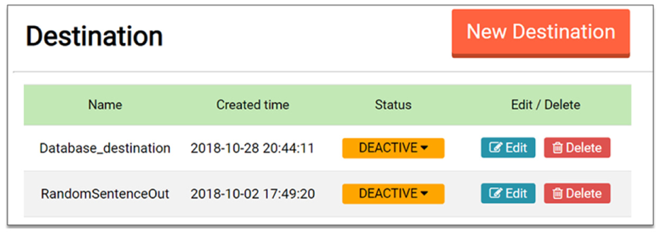
Screenshot of the destination menu page.

Configuration of the destination creation page.
Plan menu
Figure 22 shows the configuration of the plan menu page. In ⓐ, we can see the plan names, creation and modification dates, and execution status. The button ⓑ is go to the plan creation page. The button ⓒ shows the execution status of the plan, and we can execute the plan by pressing the button. Through this execution, the sampling and filtering included in the plan are processed in the Storm cluster. The button ⓓ acts to remove the corresponding plan.

Screenshot of the plan menu page.
Figure 23 shows an example screenshot of the plan creation page. In ⓔ, it gets the plan name and checks the redundancy of the given name. In ⓕ, it shows a list of user-created sources, destinations, and sampling and filtering topologies. The user selects the desired items from the list, and moves those items to the region ⓖ by the dragging and dropping function. The region ⓖ is a panel that constructs a plan by locating the selected items and by connecting links between the items. As shown in the figure, if we drop a source on a panel, it shows the source name and the data schema; if we drop a sampling (or filtering) topology on a panel, it shows the additional input parameters for the sampling (or filtering).

Configuration of the plan creation page.
Sampling and filtering results of SPMgr
In this section, we present the sampling and filtering results for the actual data stream using SPMgr. As the sampling method, we evaluate the systematic sampling and hash sampling, and as the filtering method, we do the query filtering and the Kalman filtering.
Systematic sampling
As the input data, we use the temperature data of the nuclear power plant obtained from the Korea Open Data Portal. 30 The temperature data has 2048 records, and we repeatedly input those data into SPMgr as the continuous stream format. Figure 24 shows the results before and after applying the systematic sampling to the temperature data. Graph ⓐ of Figure 24 shows the original temperature data. The plan for this systematic sampling is in Figure 25. As shown in the figure, the sample extraction interval is set to 30, so the every 30th record of the data stream is extracted periodically. Graphs ⓑ and ⓒ of Figure 24 show the sampling results. We here note that SPMgr greatly reduces the number of records from 2048 to 68, but its sampling results well reflect the overall tendency of the original data stream.
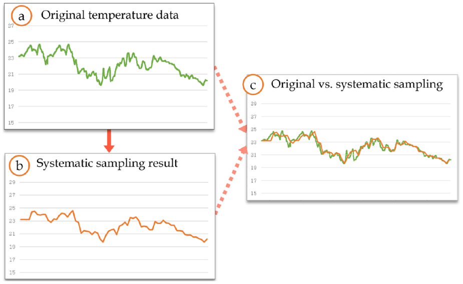
Systematic sampling result for the temperature data of the nuclear power plant.

An example plan of the systematic sampling for the temperature data.
Hash sampling
As in the systematic sampling, we use the temperature data of the nuclear power plant. The hash sampling parameters include sample size, window size, and hash function. In the experiment, we set the sample size to 100 and the window size to 400, as shown in Figure 26. That is, we extract 100 samples for every 400 data inputs. As the hash function, we use

An example plan of the hash sampling for the temperature data.

Hash sampling result for the temperature data of the nuclear power plant.
Query filtering
As the experimental data, we use the actual tweet data received through the Twitter API. 31 The tweet data consist of six fields: user name, language, region, creation date, number of users, and content. Figure 28ⓐ shows some examples of the tweet data. In the experiment, we set the query to “language equal ko” as shown in Figure 29, and SPMgr filters out only the tweet in which the language is Korean as the result. Figure 28ⓑ shows that only tweets whose language is set to Korean are filtered.

Query filtering result for the tweet data.

An example plan of the query filtering.
Kalman filtering
We use the power consumption data of UCI machine learning repository 32 as the input data. The graph ⓐ of Figure 30 shows the original data. To confirm the operation of Kalman filtering, we use the input data with white noise as shown in the graph ⓑ. Figure 30ⓑ represents the noisy input data generated by adding the normal distribution-based noise to the original data. Figure 30ⓒ shows the Kalman filtering result applied to the noisy input data of Figure 30ⓑ. Through the figure, we can see that the data generated by Kalman filtering is very similar to the original data.

Kalman filtering result for the UCI power consumption data.
Related work
StreamFlow 14 is the only Storm-based distributed workflow manager. StreamFlow is an open source tool for easily creating and monitoring Storm topologies, and Figure 31 shows its internal configuration. The security filter protects StreamFlow applications from unauthorized requests. The Web UI provides a responsive Web interface to configure and monitor the Storm topology. Figure 32 shows an example screenshot of creating a topology in StreamFlow. The core services handle user requests, such as setting defaults and checking referential integrity. The datastore stores and maintains StreamFlow or user’s work results. The Storm engine delivers commands to the Storm cluster. StreamFlow processes all the core functions through REST services, which send and receive data in JSON format.

System configuration of StreamFlow.
An example of creating a topology in StreamFlow.
As we explained through Figures 31 and 32, StreamFlow is similar to the proposed SPMgr in the aspect of topology configuration and management for Storm. However, StreamFlow does not provide full functionality for topology management, and it has not released any new versions since 2015. In addition, since StreamFlow needs to create the topology every time, it may lose data streams due to the restart when the input data structure or algorithm changes.
WSO2 Stream Processor (WSO2 SP) 13 is an open source stream processing workflow platform that uses streaming SQL to query data streams. Figure 33 shows the structure of WSO2 SP, which inputs and outputs streams through Kafka similar to the proposed SPMgr. WSO2 SP provides various query algorithms such as complex event processing, incremental time series aggregation, and machine learning for various stream processing. These algorithms use the WSO2 Siddhi stream processing engine 33 rather than Apache Storm. Siddhi provides various algorithms for integration, analytics, and intelligence, but these abstracted algorithms are not implemented for sampling and filtering purposes. Therefore, in order to operate the sampling and filtering in WSO2 SP, we need to implement additional algorithms on top of Siddhi, which can be considered as a separate future study.

Architecture of the WSO2 Stream Processor.
Conclusion
In this article, we designed and implemented SPMgr, a dynamic workflow manager that performed sampling and filtering functions for data stream refinement in a distributed cluster environment. To do this, we first derived the problems of low availability and no integration in the processing of data streams in Apache Storm. We then presented the concept of module separation and platform integration to solve those problems in SPMgr. We summarized main contributions of SPMgr as follows. First, we implemented Storm-based sampling and filtering topologies for data stream refinement. Second, we presented the concept of a plan model that connected data collection, sampling and filtering, and output modules to Apache Kafka. Through the plan model, we could change the module even during operation, greatly improving the availability of Storm and improving the flexibility of module configuration. Third, we designed and implemented an integrated framework to operate and manage Storm, Kafka, and database as a single system. Fourth, we provided a Web UI that could visually create, modify, and monitor plans by implementing the Web-based client. Fifth, through the experimental evaluation, we showed the operation procedure and processing results of SPMgr. In particular, we presented the detailed operation procedures of SPMgr by configuring the plan through the Web client, and confirmed that it processed the sampling and filtering topologies correctly for the actual data streams. Through SPMgr implemented in this article, we can easily exploit the refinement functions for big data stream objects in the Storm-based distributed environment.
Footnotes
Handling Editor: Zhong Shen
Authors’ note
A preliminary Korean version of this article was published in Database Research, Vol. 35, No. 1, April. 2019. This is a fully extended and completed version of the preliminary work.
Declaration of conflicting interests
The author(s) declared no potential conflicts of interest with respect to the research, authorship, and/or publication of this article.
Funding
The author(s) disclosed receipt of the following financial support for the research, authorship, and/or publication of this article: This research was partly supported by Korea Electric Power Corporation (Grant: R18XA05). This research was also partly supported by the National Research Foundation of Korea (NRF) grant funded by the Korea government (MSIP) (NRF-2017R1A2B4008991).