
Abstract
Due to the unique and contactless way of identification, radio-frequency identification is becoming an emerging technology for objects tracking. As radio-frequency identification does not provide any distance or bearing information, positioning using radio-frequency identification sensor itself is challenging. Two-dimensional laser range finders can provide the distance to the objects but require complicated recognition algorithms to acquire the identity of object. This article proposes an innovative method to track the locations of dynamic objects by combining radio-frequency identification and laser ranging information. We first segment the laser ranging data into clusters using density-based spatial clustering of applications with noise (DBSCAN). Velocity matching–based approach is used to track the location of object when the object is in the radio-frequency identification reading range. Since the radio-frequency identification reading range is smaller than a two-dimensional laser range finder, velocity matching–based approach fails to track location of the object when the radio-frequency identification reading is not available. In this case, our approach uses the clustering results from density-based spatial clustering of applications with noise to continuously track the moving object. Finally, we verified our approach on a Scitos robot in an indoor environment, and our results show that the proposed approach reaches a positioning accuracy of 0.43 m, which is an improvement of 67.6% and 84.1% as compared to laser-based and velocity matching–based approaches, respectively.
Keywords
Introduction
With the development of IoT (Internet of Things), there is an increasing demand for location-based services (LBSs). Global positioning system (GPS) is superb at positioning in outdoor environments, but it becomes useless in indoor environments due to the occlusions of the buildings. 1 Indoor localization draws more and more attention to the researchers in recent years. For example, Yasir et al. 2 introduced an indoor positioning system based on visible light and accelerometer measurements. Zhuang et al. 3 proposed an indoor positioning platform that integrated different wireless access points for indoor positioning. As one of the key components of the IoT, radio-frequency identification (RFID) provides a cost-effective solution for the identification of object.4,5 The tags are small and does not need any batteries, which make them suitable for the tracking of the assets in many industrial environments. Especially, the long-range passive ultra-high frequency (UHF) RFID technology can provide a reading range up to 10 m. As compared with vision and laser technologies, RFID has the advantages of non-contact and non-line-of-sight, which have the potential for tracking objects in many commercial environments, for example retail and logistics. 6
Based on the information provided by the reader (signal strength or phase), different techniques are used for the positioning purposes, for example, received signal strength (RSS),7,8 angle of arrival (AOA), 9 time of arrival (TOA), 10 and time difference of arrival (TDOA). 11 For example, Liu and colleagues12,13 proposed a LANDMARC system that achieves the localization of object by comparing the signal strength from multiple reference tags. They used a weighting algorithm to calculate the position of an unknown tag. Instead of deploying multiple readers in the environment, the system used reference tags to reduce the overall system cost. A number of researchers exploit the signal strength for the positioning of RFID tags.14–16 These approaches require modeling of the signal propagation, which is usually very hard in practice and is easily influenced by many environmental factors. The use of the AOA and the TOA requires high hardware costs and therefore has low practicability. In addition, one can also use RFID phase information for positioning. But this method has the problem of phase ambiguity, which leads to a very limited positioning accuracy. Some researchers proposed multi-frequency carrier 17 and linear-frequency modulation 18 methods to resolve phase ambiguity, but these methods have higher requirements for hardware.
Although RFID can be used to identify an object, RFID does not provide the distance or the bearing information to an object. The laser range finder can provide accurate distance information according to the laser beam. Therefore, many researchers use laser range finder to locate and track objects. For example, an event-based algorithm is proposed for the localization of a mobile robot by using a fixed laser range finder. 19 Wang et al. 20 used a single Lidar to achieve indoor positioning of a mobile robot based on weighted parallel iterative closed point (WP-ICP) with interpolation. The WP-ICP algorithm results in faster convergence for pose estimation, but it is easily affected by static or dynamic unknown objects in the environment. Although a precise distance information can be obtained from a laser range finder, it needs complex algorithms to recognize the object from a large amount of scanning points. In order to do this, a prior knowledge of the object has to be known in advance, for example, shape of the object.
As different sensors might have different drawbacks, which can be compensated for each other, many researches use sensor fusion techniques to achieve a robust and precise indoor positioning system. Zhang et al. 21 fused RFID and inertial navigation system (INS) based on extended Kalman filter (EKF) to achieve object localization in a multi-story building. An adaptive sensor fusion method which automatically compensates for bias between a laser range finder and video camera was presented. 22 Chen et al. 23 proposed an environment knowledge-based indoor positioning system by integrating Lidar, odometer, and light sensor with an EKF. The integration of RFID and laser ranging information for positioning also attracts many researchers’ attentions. From a perspective of sensor fusion, the laser range finder provides distance to an object, while the RFID directly identifies the object. Therefore, RFID and laser can complement each other’s shortcomings. However, in practical applications, the reading ranges of RFID and laser are different. The range of laser sensor is usually larger than the RFID reading range. In order to continuously track dynamic object when the object is out of the RFID reading range, we propose a dynamic object localization method based on the fusion of RFID and laser ranging information. When the object is in the range of RFID sensor, we use velocity matching to fuse RFID and laser information and then apply a particle filter to track the object. This idea is also used in many fields, for example, dynamic target positioning 24 and alignment of different sensor measurements. 25 To segment the raw laser ranging measurements into clusters, we use the density-based spatial clustering of applications with noise (DBSCAN) clustering algorithm. 26 The algorithm can quickly find clusters of arbitrary shapes and deal with noise points, 27 which is widely used in the fields of image processing and data mining. Otherwise, we track the object based on clustering results and the previous estimation. Our approach expands the tracking range as compared to our previous research and ensures a continuous tracking of an object when the RFID information is not available. The proposed system can be applied to many areas such as human-robot interaction and object tracking.
The remainder of the article is organized as follows. The “Related work” section reviews the existing work RFID-based approach, dynamic target-tracking approach, fusion with laser ranging information, and fusion with other sensor. The “Overview” section briefly describes our positioning system. The “Laser clustering based on DBSCAN” section presents the working principle of the DBSCAN clustering algorithm and calculates the laser-based velocity based on the clustering results. The “Velocity matching” section describes the calculation of phase-based velocity and calculates the similarity between the laser-based velocity and the phase-based velocity to achieve velocity matching. “Tracking the dynamic object based on the particle filter” section presents the object tracking using a particle filter. “Experiment” section shows the experimental setup and results. Finally, “Conclusion” section presents the conclusion and the future work of this article.
Related work
This section gives a thorough overview of the work related to the tracking using RFID techniques. We divide the related work into the following three categories: RFID-based approach, fusion with laser ranging information, and the fusion with other sensors. Meanwhile, we discuss their continuous tracking capabilities and their advantages and disadvantages.
RFID-based approach
Many RFID readers report the signal strength of the detected tags, which can be used to infer the location of the tag. Two typical systems using this technique are VIrtual Reference Elimination (VIRE) 28 and SpotON. 29 AOA is also exploited for the positioning of RFID by several researchers. Zhou et al. 30 estimated the AOA by phase difference and showed the feasibility to use AOA for the localization. The phase is easily affected by environmental factors as well as the radiation patterns of reader and tag antennas. TOA shows very good accuracy for positioning, but it is difficult to achieve time synchronization. To overcome this problem, time difference of arrival (TDOA) has been employed, but the measurement is susceptible to interference from non-line-of-sight factors. A location-tracking system is proposed based on measuring the phases from multiple spatially distributed antennas at a single carrier frequency. 31 Kim et al. 32 proposed a method to fuse TDOA and AOA for positioning using dual indirect Kalman filter (DIKF). A fine-grained positioning system was presented using the phase information from the COTS RFID products. 33
Dynamic target-tracking approach
Dynamic target tracking is widely used in intelligent monitoring, human–robot interaction, virtual reality, and robot navigation. For example, Zou et al. 34 combined image and point cloud data to construct map of an environment and track the position of moving targets in the view. To improve the tracking accuracy of dynamic targets, they used the three-dimensional (3D) motion model and the shape of the target to deal with obstacle occlusion problem. Lopes et al. 35 proposed a dynamic target-tracking system using blur images. Li et al. 36 proposed an adaptive distributed sampling online co-search method to achieve dynamic target tracking. They formed the posterior probabilities of an unpredictable moving target using only local information and constructed a piecewise function to describe the likelihood of measurements. Xiao et al. 37 designed an algorithm to track arbitrary objects in the video sequences based on adaptive clustered decision tree.
Fusion with laser ranging information
As laser range finders provide very precise distance measurement to the surroundings, some researchers exploited the possibilities to integrate RFID and laser ranging information for positioning. For example, Lin et al. 38 proposed an indoor mapping approach that combines active RFID and laser technology. They initialized the robot’s global configuration by recognizing active RFID tags in the indoor environment and used the laser range finder to build the metric map of an environment. Gong et al. 39 presented an object-positioning algorithm based on RFID and laser range finder. They used RFID to estimate the rough existing area of the object and obtained a precise position of the object using a laser feature–detection algorithm. He et al. 40 used the RFID phase difference and the laser to calculate the object velocity, and then performed velocity matching. Then, based on the matching result, they located the dynamic target according to a particle filter. In our previous work, 41 we proposed a way for the localization of moving object using a particle filter by incorporating RFID phase and laser-based clustering from two-dimensional (2D) laser range data. We achieved the tracking of the object by a comparison of the velocity between the RFID phase velocity and laser-based velocity. However, this method requires the object to be in the range of the RFID reader. In this article, we show that we can achieve object tracking even if it is out of the RFID detection range.
Fusion with other sensors
Zampella et al. 42 presented an indoor positioning system that fused foot-mounted inertial measurements and radio frequency (RF) measurements based on a particle filter. The RF system consisted of an RFID tag in the waist and an ultra wide band (UWB) receiver in the chest. In order to overcome the problem of insufficient coverage of RFID signals, some researchers proposed to combine RFID and INS through Kalman filtering to achieve continuous tracking of pedestrian.43,44 A positioning system that fuses RFID and sonar sensors was presented by Choi et al. 45 Xie et al. 46 proposed an object-recognition method based on RFID and depth camera. Liu et al. 47 proposed a method for quickly tracking dynamic targets based on the RSS measurements from a pair of RFID antennas. Duan et al. 48 proposed Tagvision that achieved the tracking of fine-grained objects by combining computer vision and RFID. This method combined the location information provided by the vision system with the phase data from the RFID to achieve a good accuracy.
Table 1 shows a comparison of different approaches. The existing approaches either requires a prior knowledge about the propagation of the radio signal, or fails to track the moving object when it is out of the RFID reading range. The proposed approach does not need any modeling of the signal propagation and allows the continuous tracking of an object when the object is not in the range of the RFID reader.
Comparison of different approaches.

RSS: received signal strength; AOA: angle of arrival; TDOA: time difference of arrival; RFID: radio-frequency identification; UWB: ultra wide band; INS: inertial navigation system; KF: Kalman filter.
Overview
This article introduces a positioning method that fuses RFID and 2D laser range finder based on the particle filtering for the tracking of a dynamic object. The proposed approach allows the continuous tracking of an object when the object is out of the RFID reading range. As shown in Figure 1, the entire positioning system can be divided into three parts. The first part uses RFID reader and 2D laser range finder to perceive the measurements from the environment. The second part processes the measurements collected from RFID and laser range finder. The third part uses a particle filter to achieve tracking and localization of a dynamic object. The mathematical symbols and their meanings used in this article are listed in Table 2.

System overview.
Mathematical symbols and their meanings.

RFID: radio-frequency identification.
In the first part, we collect the measurements through RFID reader and 2D laser range finder. The RFID reader controls the antenna to scan the tagged dynamic objects in the environment, and the 2D laser sensor is used to measure the distance and angle from the surrounding obstacles in an environment. Then the information detected by the two sensors is stored the database. The second part processes the measurements collected from the previous part. In this part, we process the acquired data separately based on whether RFID information is available. When the moving object is in the range of RFID sensor, we combine RFID and laser information for the tracking. First, we calculate the phase-based velocity of the moving object by the RFID phase difference between two successive timestamps. The laser ranging data are segmented into different clusters using DBSCAN.
49
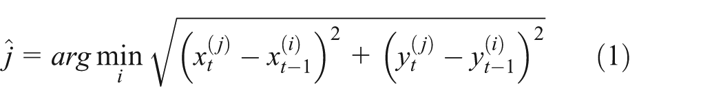
The two closest clusters at the adjacent time are regarded as the same obstacle, and the distance between the two clusters is used to estimate the laser-based velocity. Second, we perform velocity matching to compute the similarity between phase-based velocity and laser-based velocity. Based on the matching results, we choose the best
Laser clustering based on DBSCAN
DBSCAN clustering of laser ranging data
The 2D laser range finder records distance information to the objects in the scanning environment. To facilitate subsequent clustering, we assume

Example of the raw laser data at a time.
In order to better determine the position of the object, we need to cluster the laser ranging data. As can be seen from Figure 2, the laser points around the obstacle are more concentrated, and we can cluster the laser ranging points based on theirs densities. DBSCAN is a density-based clustering algorithm, which can cluster dense points of arbitrary shape and remove the abnormal points. Therefore, this article chooses DBSCAN algorithm to cluster the two-dimensional laser ranging data. In DBSCAN clustering, for each point in a cluster, the number of its
For DBSCAN clustering, we first assign an initial mark −1 to all laser points. From this mark, we can determine whether the laser point has been processed. Next, we divide the marked laser points into core points, border points, and noise points. More specifically, for a given point

DBSCAN flow chart.
We perform clustering after finding the core points and border points. If a point is the core point, we form a cluster by expanding its
Estimate moving velocity of a cluster
For each cluster
where

The velocities of the clusters will be used for velocity matching in Section “RFID and laser velocity matching.”
Velocity matching
RFID phase velocity estimation
This article uses RFID phase information to estimate the velocity of the object, which is referred to as phase velocity in this article. The phase information of the RFID is a periodic function (with a period of

where

where
RFID and laser velocity matching
At a specific time, there may be many moving or static objects (i.e. clusters) in the environment. In the simplest case, the cluster with the closest velocity to the phase velocity is considered to be the moving object we want to track. Therefore, for a given cluster, we perform velocity matching, that is, compare its velocity against the phase-based velocity by a similarity measures

where
Tracking the dynamic object based on the particle filter
Our goal is to estimate the location

where
In the literature, many implementations of Bayesian filter have been proposed. The particle filter demonstrates good capability in nonlinear and non-Gaussian systems, and has been successfully used in many fields, for example object tracking, navigation, and positioning. Therefore, this article chooses the particle filtering as the implementation. In the particle filtering, the probability density function is represented by a set of particles, that is,
Prediction
This part predicts the particle location

where
Update
The update stage computes the weight of each particle based on the sensor measurements. Based on the availability of the RFID information, we need to update the particle weights according to the following two cases
1. Update weights using
For the case that the RFID signal is available, the weights are updated based on the
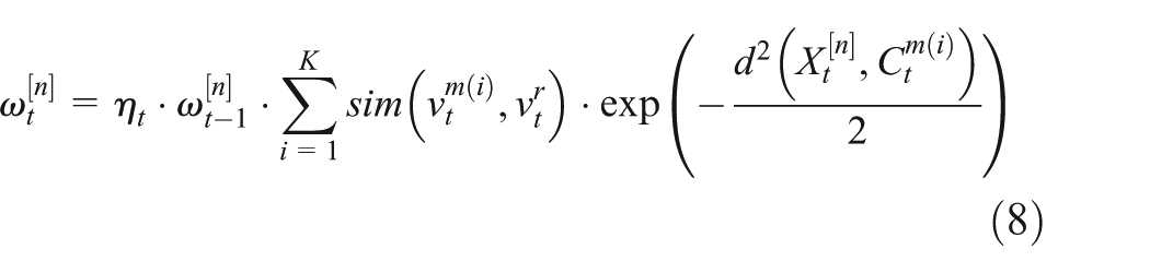
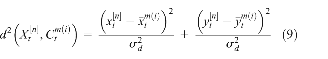
where
2. Update weights using laser cluster when the RFID information is not available.
When the RFID information is not available, we use the laser ranging data alone for the updating of the particle filter. This ensures the continuous tracking of the object when the object is out of the RFID reading range. In reality, the distance that an object moves within a time interval should not exceed a certain range

Resampling
Finally, the resampling deals with the problem of particle degradation that occurs after several times of iterations. We reproduce a set of particle sets by removing low-weight particles and replicating high-weight particles. The new set of particles are used for the prediction and updating in the next iteration.
Experiment
Experimental setup
We verify the feasibility of our algorithm in an indoor environment. The experimental environment consists of walls, obstacle cartons, and ordinary pedestrians. The measurements are collected using a Scitos G5 robot. The robot is equipped with an Impinj Speedway Revolution R420 UHF RFID reader. The reader provides a reading range up to 7 m. It takes approximately 0.3 s for each inquiry of the RFID measurement. Two antennas (Lairs Technologies SS8688P with an antenna gain of 9.0 dBi) are connected to the RFID reader. The antennas were installed at a height of 1.2 m on the robot and were parallel to the front of the robot. Moreover, the robot is equipped with a SICK S300 laser range finder (with a maximum reading range of 29 m and scan angle of 270°).
During our experiment, a person walked on a rectangular path of 10 × 5 m with a passive tag (Squiggle, Alien Technology, San Jose, CA, USA). This person walked around the rectangular area four times at a speed of 0.4 m/s. In addition, there are multiple static obstacles as well as moving obstacles (human) in the experimental scene. The sampling rate of the RFID reader is set to be 0.4 s per sample. In total, there are a number of 764 measurements recorded during the walking. Furthermore, the robot is fixed at 1 m from the midpoint of the long side of the rectangular path. As shown in Figure 4, there are multiple obstacles around the experiment. At the same time, other pedestrians moved randomly in the area.

An overview of the experimental setup.
Evaluation of the positioning accuracy under different approaches
In this series of experiments, we used three different approaches to evaluate the tracking accuracy. For the first approach (i.e. velocity matching), we perform velocity matching between the laser cluster velocity and the RFID phase velocity when the RFID information is available. The matching results are used to update the weights of the particle filter. The same implementation is also used by Fu et al. 41 For the second approach (laser-based tracking), we ignored the RFID information and only used laser clustering results for tracking by assuming that the initial location of the object is known. The third approach (i.e. our approach) combines the previous two approaches. The comparison of these three approaches is shown in Table 3.
Comparison of the tracking accuracy under different approaches.

For this series of experiments, we set the parameters as

Ground truth and estimated trajectory under different approaches.

Estimation error at different timestamps under different approaches.
In order to verify the robustness of the entire positioning system, we added two dynamic targets carrying RFID tags based on the original experimental scene in Figure 7. In addition, the experimental parameters are set to be the same as the original experimental parameters, and the positioning results are shown in Figure 8. As can be seen from Figure 8, when multiple dynamic tags are used, the overall positioning effect is consistent with the real path and the average positioning error of the three tags is 0.54 m, which is only 0.1 m worse than the positioning error of a single target (24%). The experimental results show that our approach is able to track the positions of multiple objects with a good positioning accuracy.

Multiple tags experimental environment setup.

Ground truth and estimated trajectories of multiple tags.
The effect of different antenna configurations
The number of antennas directly affects the detecting range of the RFID sensor. Therefore, in the second series of experiments, we analyzed the effect of different antenna configurations on the positioning accuracy. We fixed
Positioning accuracy under the impact of different antenna combinations.

Tracking accuracy under the impact of
and
in DBSCAN
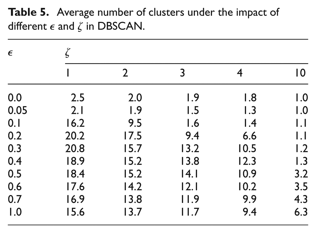
Since the DBSCAN clustering is controlled by two parameters radius
Table 5 shows the average number of clusters under different
Average number of clusters under the impact of different

Clustering results of different
The positioning accuracy under the impact of
Tracking accuracy under the impact of

The effect of different numbers of particles
Since we use the particle filtering for the tracking, the number of particles
Effect of particle number
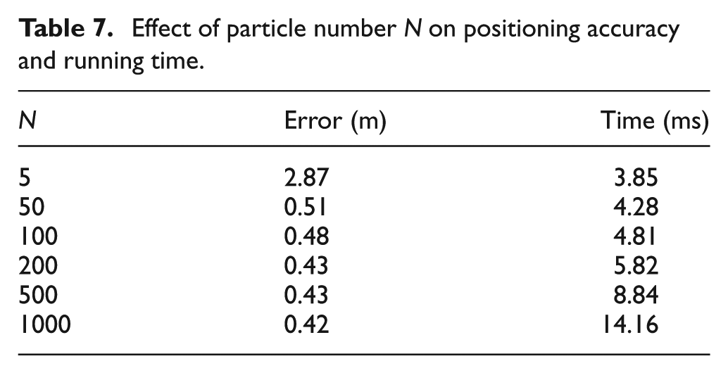
As can be seen from Table 7, a small
Impact of the range
For the laser cluster tracking, the distance that an object moves at two continuous times should be within a certain range
Influence of the value of range

Impact of
best match and translational coefficient
Positioning accuracy under the impact of different

As can be seen from Table 9,
Conclusion
This article proposed an approach to fuse RFID and laser information to achieve dynamic object positioning using a particle filter. Due to the limited range of the RFID sensor, we use the laser range information to continuously track the position of a moving object. We estimate the phase velocity of the object when RFID measurements are available. This velocity is matched against the laser cluster–based velocity to localize the moving object. If the object is not in the range of the RFID, we only use laser clustering results to track the object. By combining the previous estimated position, we select the closest cluster to update the particle filter. Our approach leads to a positioning accuracy of 0.43 m, which is an improvement of 67.6% and 84.1% as compared to laser tracking and velocity matching, respectively. However, our system will fail to track the moving object when it is occluded by obstacles for a long time. Second, the sampling frequency used in this article is set to 0.3 s. Our approach will fail if the object moves too fast, for example, the moving distance in two continuous measurements is larger than
Footnotes
Acknowledgements
The authors would like to thank Dr Chin Keong Ho from A*STAR, Singapore, for the discussion of the paper.
Handling Editor: Amiya Nayak
Declaration of conflicting interests
The author(s) declared no potential conflicts of interest with respect to the research, authorship, and/or publication of this article.
Funding
The author(s) disclosed receipt of the following financial support for the research, authorship, and/or publication of this article: This research is supported partially by the National Natural Science Foundation of China (grant nos.: 61601381, 61701421, and 61471306), partially by the China’s 13th Five-Year Plan in the Development of Nuclear Energy (grant no.: 20161295), partially by the Sichuan Province Science and Technology Innovation Seed Project (grant no.: 2018047), partially by Sichuan Science and Technology Program (grant no.: 2019YFH0161), partially by the Postgraduate Innovation Fund Project by Southwest University of Science and Technology (grant no.: 18ycx117).