
Abstract
The localization accuracy of the existing methods for indoor Wi-Fi access points ranging-based localization depends on the accuracy of the received signal strength measured. Because the existing ranging-based methods are interfered by various indoor environmental factors, it is difficult to accurately measure the received signal strength, which leads to the problem of low localization accuracy of the indoor Wi-Fi access points. An indoor Wi-Fi access points localization algorithm based on improved path loss model parameter calculation method and recursive partition is proposed in this article. The algorithm recursively partitions the region where the target Wi-Fi access points are located according to the idea of quadtree partition, and partitions it into same sub-grids, which is sequentially performed until the sub-grids are smaller than the set threshold. The detection device is used at the detection location of the grids to measure the received signal strength, which is from the detection points to the target access point, the grid center point is used as the location of the candidate target access point, the parameters in the path loss model are calculated by using the signal strength differences between the detection points, and then the distances between the detection points and the target access point are calculated by using the signal strength values from the detection points to the target access point. Finally, the location of the target access point is estimated by executing a localization algorithm, and the location of the grid center point closest to the target access point is taken as the location of the target access point. The experimental results show that under the premise that the target access point can be found, the proposed algorithm reduces the use of the device and improves the localization accuracy compared with the typical localization method.
Introduction
With the rapid development of wireless networks and popularity of mobile intelligent devices, various types of Wi-Fi access points (APs) are constantly appearing, such as routers, laptops, smart phones, and tablet computers, which provide convenience for people while accessing the Internet, and it is convenient for criminals to engage in illegal activities. They use illegal Wi-Fi to embed Trojans or hacking programs into users’ devices, to illegally collect and steal user information, and use information hiding technology1,2 to pass out the hidden information. Therefore, research on indoor Wi-Fi APs localization technology is of great significance for determining the locations of malicious APs and improving the awareness of user privacy protection.
Existing ranging-based localization methods calculate the propagation distance by utilizing the characteristics of the Wi-Fi signal propagation process. Commonly used features include time of arrival (TOA), 3 time difference of arrival (TDOA), 4 angle of arrival (AOA),5,6 and received signal strength (RSS).7,8 Based on the TOA localization algorithm, the distance between the detection point and the target AP is calculated by the propagation time of the Wi-Fi signal. Since the signal is propagation at the speed of light, the accuracy of TOA for time measurement is highly demanding, and strict clock synchronization between the detection point and the target AP is required, which makes it difficult to apply in practice. In Liu et al., 9 the location of the target AP is determined by using TOA. Based on the TDOA localization algorithm the location of the target AP is calculated by the time difference between the Wi-Fi signal reaching different detection sources. It is necessary to ensure that all the detection sources are time synchronized and the hardware cost is high. In Shen et al., 10 the location of the target AP is determined by using TDOA. Based on the AOA localization algorithm, the location of the target AP is determined by measuring the angle values between two or more detection points to the target AP, and the antenna array is required to measure the arrival angle of the received Wi-Fi signal, resulting in higher hardware cost. In Xu et al., 11 the location of the target AP is determined by using AOA.
The algorithm that based on the RSS ranging is aimed to convert the RSS into distance by using the path loss model and then use a localization algorithm such as least squares algorithm and particle swarm optimization algorithm to obtain the location of the target AP. The algorithm that based on the RSS ranging algorithm requires low hardware cost and is simple to operate, so it is widely used. However, due to the influence of indoor environmental factors, such as multipath, non-line-of-sight, and scattering, it is difficult to accurately measure the RSS, resulting in a large error in the path loss model parameters calculated by RSS, and finally there is a large error in the distance converted by RSS.
To overcome the shortcomings of the above existing methods, an indoor Wi-Fi APs localization algorithm based on improved path loss model parameter calculation method and recursive partition is proposed in this article. The algorithm recursively partitions the length and width of the region where the target Wi-Fi AP is located, calculates the parameters in the path loss model by the RSS differences between the detection points, calculates the distances from the detection points to the target AP by the RSS values of the detection points to the target AP. Finally, a localization algorithm is executed to estimate the location of the target AP. The method can reduce the hardware cost and improve the localization accuracy of the Wi-Fi AP.
The main contributions of this article are, first, in the same indoor environment, the calculated parameters of the path loss model are more accurate than the existing methods; second, the proposed method reduces the use of the device and improves the localization accuracy compared with the typical localization methods.
The rest of this article is organized as follows. The next section briefly introduces the Wi-Fi AP localization method based on RSS ranging and introduces the path loss model and the existing ranging-based localization algorithm in turn. The proposed indoor Wi-Fi APs localization algorithm based on improved path loss model parameter calculation method and recursive partition is elaborated in details in the “Proposed algorithm” section, including the basic idea of the algorithm, the main steps. The detection equipment use is introduced in the “Detection devices” section. The experimental results are given in the “Experimental results and analysis” section. Finally, this article is concluded in the “Conclusion and future work” section.
Introduction of Wi-Fi APs localization method based on RSS ranging
The localization methods based on RSS ranging, the RSS values from the detection points to known AP and the target AP are measured at several detection points, respectively. The parameters in the path loss model are calculated by using the measured RSS values from the detection points to known APs. Then, the RSS values from the detection points to the target AP measured at the detection points are converted into corresponding distances by the path loss model, and finally the location of target AP is estimated by using localization algorithms, such as trilateral localization algorithm, least squares algorithm, and particle swarm optimization algorithm.
Path loss model
Path loss model 12 is the most commonly used conversion relationship model for RSS and distance in indoor environments. The model formula is as follows

In formula (1), the traditional method of calculating the parameters of the path loss model is different from that of the proposed one. The specific method of calculating the parameters are as follows:
In the traditional path loss model,
In the proposed path loss model, a self-made directional detection device is used to determine the direction of the strongest signal of the target AP, and the detection points are selected along the direction to collinear with the target AP. The RSS values from each detection point to the target AP are measured by the detection device. Two collinear detection points are selected arbitrarily.
In formula (1), parameters
Localization algorithm
Trilateral localization algorithm (TLA)
Set
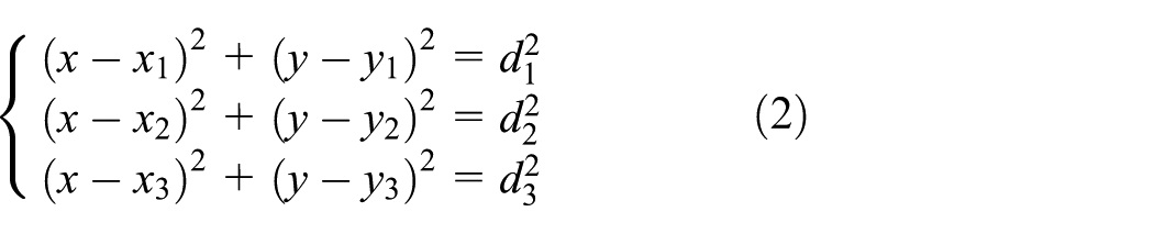
The location coordinate
Least squares algorithm (LSA)
The least squares algorithm is the best function match for finding data by minimizing the sum of squares errors. Unknown data can be easily obtained by using the least squares algorithm, and the sum of squares errors between the obtained data and the actual data is minimized. The formula for the least squares algorithm most commonly used in indoor localization is as follows
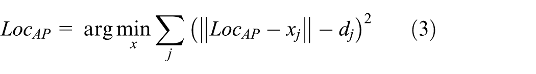
where the location of the target AP is
Particle swarm optimization algorithm (PSOA)
The particle swarm algorithm
17
simulates birds in a flock by designing a massless particle. The particle has only two properties: velocity
The updated speed and location of the particles are as follows
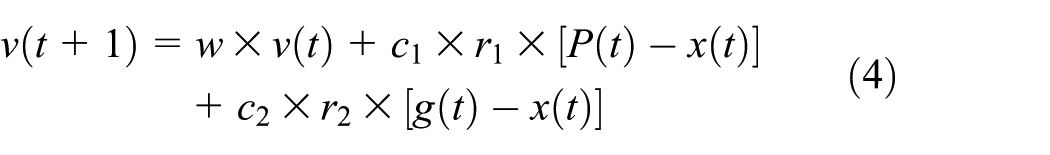

where w is the inertia weight, providing a balance between local search and global search, the inertia weight is significant, it is convenient for global search, the inertia weight is small, and it is convenient for local search.

In the experimental area of 50 m × 50 m, the number of particles is 20, the number of samples is 60, and the localization accuracy is about 1.5 m.
However, there is a large error in converting the measured RSS into the corresponding distance by using the above path loss model. On the one hand, there is a certain error in the measured RSS itself, and on the other hand, there is a certain error in the parameter of the path loss model calculated by the RSS, which eventually leads to a large error in the distance converted by RSS.
Proposed algorithm
Aiming to solve the problem pointed in the previous section that existing deficiencies in the calculation method of path loss model parameters based on the RSS ranging method result in large localization error, an indoor Wi-Fi APs localization algorithm based on improved path loss model parameter calculation method and recursive partition is proposed in this article.
Algorithm ideas and main steps
The algorithm in this article is based on the idea of recursive partition of quadtree. The algorithm constructs a two-dimensional coordinate system according to the length and width of the region where the target Wi-Fi AP is located. The region to be located is recursively partitioned by the center points and partition into four equal grids and then recursively partitions in the four grids until the length and width of the grid are less than the threshold. The parameters in the path loss model are calculated by using the RSS differences between the detection points, and then the distances between the detection points and the target AP are calculated by using the RSS values from the detection points to the target AP. Finally, the location of the target AP is estimated by executing localization algorithm.
Algorithm details are shown in Figure 1.

The flow diagram of the proposed algorithm.
Algorithm input includes grid threshold, the coordinates of detection points, and the RSS values from detection points to the target AP measured at the detection points. Algorithm output includes the coordinate of the target AP. The main steps of the algorithm are as follows:
Step 1: Build a two-dimensional coordinate system
By measuring the length l and width w of the region to be located (or according to the number of floor tiles in the region to be located), a two-dimensional coordinate system is constructed along the length and width of the region to be located with one of the corners of the region as the origin of the coordinates.
Step 2: Whether there is a rogue AP
An AP information list is obtained by scanning nearby Wi-Fi signals using a detection device in the region to be located, including AP’s service set identifier (SSID), RSS, MAC (Media Access Control), and so forth. Determine whether there is a rogue AP through the AP’s information list. If yes, execution step 3, otherwise, the algorithm ends.
Step 3: Determine the SSID of the rogue AP.
According to the AP list information obtained in the step 2, and the MAC address of the legal AP recorded in the previous step, the MAC address that is not in the AP list information is found, that is, the AP corresponding to the MAC address is a rogue AP, and the SSID is obtained.
Step 4: Determine the number of partitions and the locations of the detection points.
By using the quadtree recursive partitioning, each time the region to be located is divided into four equal sub-grids, which are sequentially performed until the length and width of the sub-grids are simultaneously less than the set grid threshold. And take the center point of each grid as the locations of the candidate target AP.
Step 5: Measure the RSS and calculate
First, the self-made directional detection device is used to determine the direction of the strongest signal strength of the target AP, and then detection points are selected along the direction to make it collinear with the target AP. The RSS values from detection points to the target AP are measured by using the detection device at each detection point, and the RSS differences between each detection point and the starting point are calculated by arbitrarily selecting a detection point as the starting point.
Step 6: Calculate
The RSS differences of the detection points can be obtained from step 5. The distances between the detection points can be obtained by knowing the coordinates of the detection points. The obtained sets of RSS differences and distance differences are brought into the formula (1), and their mean values are taken as
Step 7: Obtain the estimated distances from the detection points to the target AP.
According to step 6, the unknown parameters
Step 8: Perform localization algorithm
By performing localization algorithms, such as trilateral localization algorithm, the least squares algorithm, and particle swarm optimization algorithm, the coordinates of the target AP and the localization error of the algorithm can be obtained through calculation.
In the above steps, step 4 and step 5 are key aspects of the algorithm. These two steps are elaborated in detail, respectively, in the following sections.
Determine the number of partitions and the location of the detection points
The proposed algorithm partitions the region to be located into equal grids by quadtree recursive partition, and takes the center point of the grid as the location of the candidate target AP at each time partition. The process of the first, second to the n-th time recursive partition is shown as follows.
As shown in Figure 2, the green dots denote the locations of the detection points in the figure. First, the location of the center point

The diagram of the idea of recursive partitioning based on quadtree.
Taking the
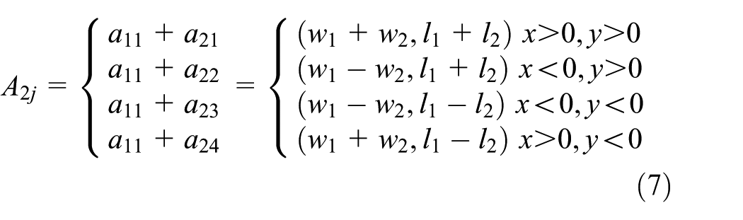
where
In the i-th recursive partitioning, the coordinates of each center point in the entire region to be located are as shown in formula (8)

where
Measure RSS and calculate
The RSS value from each detection point to the target AP is measured by using detection device. After i partitioning, there are a total of
When calculating the distance between two points, the coordinates of the starting point and the remaining detection points in the entire region to be located are calculated by the formula (8), and then the distances between the starting point and the remaining detection points are calculated by using the distance formula between the two points. Therefore, when calculating the distance for the first time,
The value of the RSS difference is the negative absolute value of RSS difference between the two detection points. The method of calculating the RSS difference between two points is similar to the method of calculating the distance between two points. Finally,
For the same target AP, the RSS values measured by different detection devices at the same detection point may be different, resulting in different localization results. The key factor of receiving Wi-Fi signal strength is the power of the wireless network card built in the detection device. The greater the receiving power of the wireless network card, the farther and stronger the received signal. Otherwise, the closer and weaker the received signal is. In addition, the receiving Wi-Fi signal strength will be affected by the overall performance of the detection device system, the speed of operation, and the transmission power of the wireless router, and so forth. Therefore, with the algorithm proposed in this article, we use three different detection devices for experiments.
Detection devices
With different detection devices pointed out in the previous section, the localization results may be different. Therefore, the following three different detection devices are used for experiment.
In most public places, such as superstores, cafes, and restaurants, the portability, accuracy, and efficiency of the detection devices are the primary considerations without special requirements and restrictions on the detection device used in the localization process. Mobile phones are the most popular items that people carry with them every day, and 96% of mobile phones currently have built-in Wi-Fi signal receiving modules. So the mobile phone model of Redmi 5 Plus is chosen as one of the detection devices, and running the self-written Wi-Fi signal strength acquisition APP on it, the Wi-Fi signal list in the scanning environment, such as the SSID, MAC, capabilities, frequency, basic service set identifier (BSSID), and RSS information, can be realized.
Mobile phones can meet the needs of most localization places. However, it is usually forbidden to bring mobile phones for special places such as secrecy rooms, military units, and government units; hence, the abovementioned mobile phone detecting devices cannot be used in these places. In response to this problem, we use the iTOP4412 development board supporting Android system as a detection device to run the Wi-Fi signal strength acquisition APP. The main modules included in the hardware equipment are Wi-Fi receiving module, iTOP4412 backplane, iTOP4412 core board, touch display, and other supporting equipment, as shown in Figure 3.
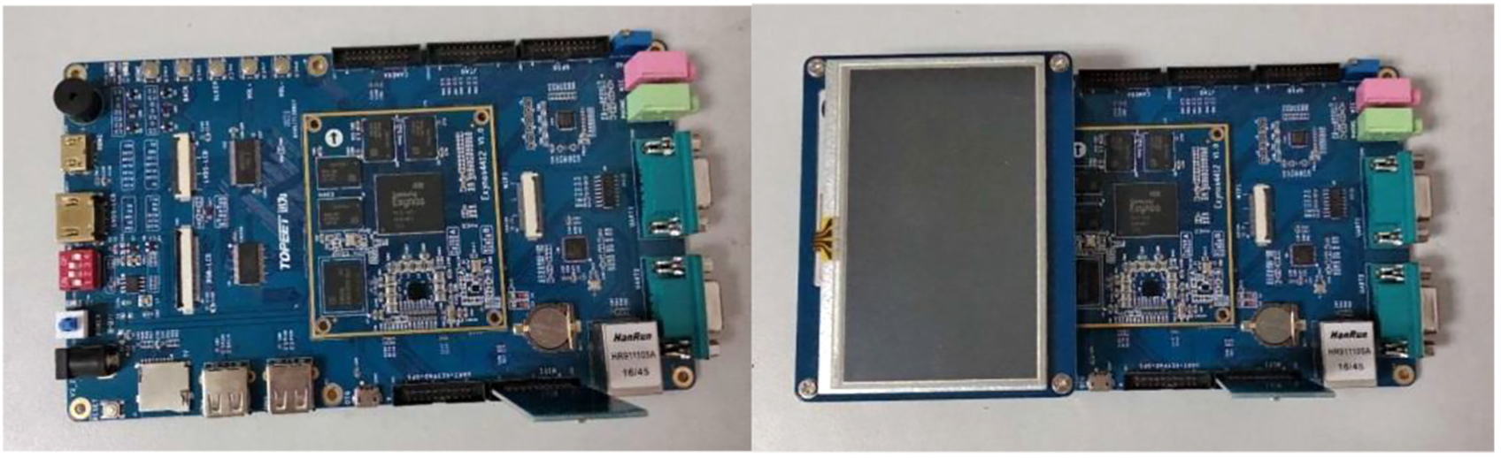
iTOP4412 development board.
Although the iTOP4412 development board can meet the needs of special places, for the same target AP, the RSS measured by the mobile phone at the same detection point is about 12 dBm higher than the RSS measured by the iTOP4412 development board, and the size of iTOP4412 development board is slightly larger and is not convenient to carry. In response to this situation, the Raspberry Pi 3 generation B+ development board is selected as the detection device. The development version is equipped with ARM Cortex-A53 CPU, the main frequency is 1.4 GHz, the memory is 1 GB and can be expanded, and it supports 802.11 ac, and Wi-Fi is detected in the all frequency bands, including current mainstream 2.4 GHz and a small amount of 5 GHz application, as shown in Figure 4. For the same target AP, the RSS measured by the mobile phone at the same detection point is equivalent to the RSS measured by the Raspberry Pi development board, and the Raspberry Pi development board is compact and easy to carry.

Raspberry Pi 3 generation B+ development board.
Through comparison of the use occasions and portability of the above three types of detection device, it can be concluded that the Raspberry Pi development board is the best choice for detection device.
Experimental results and analysis
In order to verify the effectiveness and feasibility of the proposed algorithm, the localization experiment is carried out several times in the actual environment to verify the algorithm, the comparison experiment are carried out on the algorithms of the RSS ranging based on trilateral localization, 15 the RSS ranging based on the least squares, 16 and the RSS ranging based on particle swarm optimization, 18 respectively. Compared with the RSS ranging algorithm based on trilateral localization, the RSS ranging algorithm based on the least squares, and the RSS ranging algorithm based on the particle swarm optimization, the computational complexity of the algorithm has not changed, and its complexity is using two file handles.
Experimental settings
The experiment is carried out in an area of 55 m × 12 m, which is one floor of a building which mainly consists of a corridor and 4 classrooms. The locations of six APs are arbitrarily selected during the experiment, as shown in Figure 5. The devices used in the experiment mainly have three signal acquisition devices, including mobile phone, two development boards, and a router.
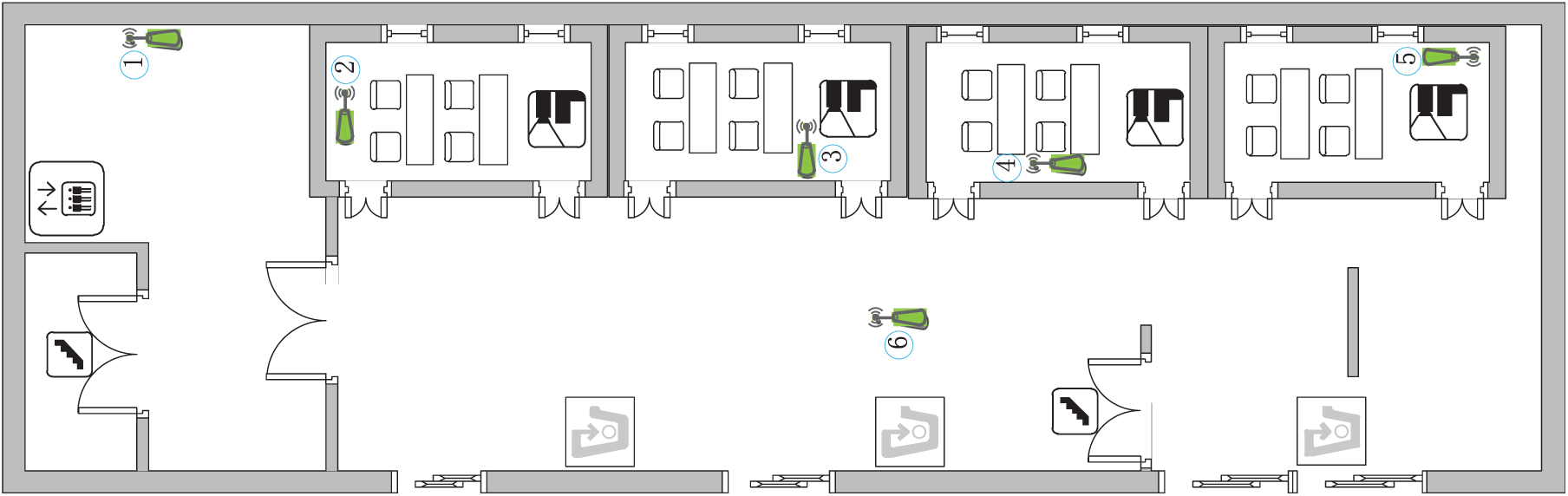
The diagram of the region to be located.
In the case that the grid threshold is set to 2.4 m, the following three types of experiments are carried out to verify the factors affecting the accuracy of the localization algorithm:
Experiment on the influence of the location of the AP on localization algorithms.
Experiment on the influence of different detection devices on localization algorithms.
Experiment on the influence of the number of detection points on localization algorithms.
Experiment on the influence of the location of the AP on localization algorithms
Since the RSS values from detection point to different target APs are different at the same detection point, the parameter
In the localization experiment of six location points, we take one of them as an example to illustrate the process of the localization results of the experiment in detail. For example, taking location 1 as an example, first, 40 detection points are selected in the region to be located. Then RSS values from detection points to the target AP are measured at detection points; according to the algorithm proposed in this article, we can get the average value of
Under the same conditions of the detection point, the comparison result of the parameter
Parameter

It can be seen from Table 1 that the parameter
The calculation methods of the original path loss model parameters and the proposed path loss model parameters are, respectively, used. The RSS ranging algorithm based on trilateral localization, 15 the RSS ranging algorithm based on the least squares 16 and the RSS ranging algorithm based on the particle swarm optimization 18 are calculated by arbitrarily selecting the locations of six different target APs in the region to be located, and analyzing the influence of AP locations on the localization algorithm. The experimental results are shown in Figure 6.

Influence of AP location on three localization algorithms.
Among them, the horizontal axis denotes six AP locations arbitrarily selected in the region to be located, and the vertical axis denotes the localization error. It can be seen from the figure that the localization error obtained by the same algorithm at different AP locations is different, so the location of the AP will affect the localization result. It can also be seen from the figure that the calculation method using the path loss model parameters proposed in this article has lower localization error than the calculation method using the original path loss model parameters.
In the region to be located, taking location 3 as the target AP, the cumulative probability of the RSS ranging algorithm based on trilateral localization, 15 the RSS ranging algorithm based on the least squares, 16 and the RSS ranging algorithm based on particle swarm optimization 18 are calculated using the original and the proposed path loss model parameters, respectively. The results are shown in Figure 7.
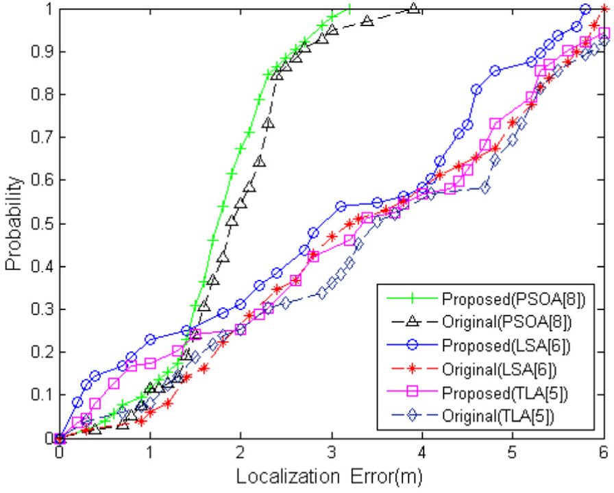
Cumulative probabilities of localization errors for three algorithms.
In Figure 7, the horizontal axis denotes localization error, and the vertical axis denotes cumulative probability. It can be seen from the figure that for the same localization method, the cumulative probability of the overall proposed algorithm is larger than the existing algorithm when the localization error is the same. For different localization methods, when the localization error is greater than or equal to 2, the cumulative probability of using the particle swarm optimization algorithm is the largest, and the cumulative probability of using the trilateral localization algorithm is the smallest.
Experiment on the influence of different detection devices on localization algorithms
For the same target AP, the RSS values may be different when different detection devices are used at the same detection point. Therefore, three different types of detection devices are used to carry out experiments at six arbitrarily selected locations in the region to be located. Under the same conditions of detection points, the comparison result between the parameter
Parameter
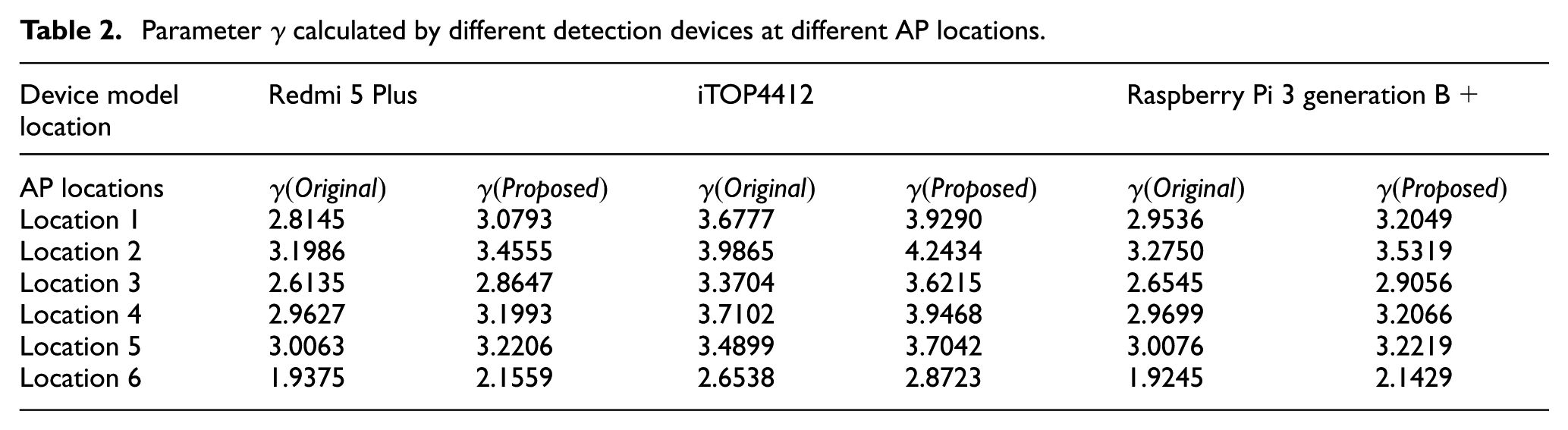
It can be seen from the data in Table 2 that the calculated parameter
The calculation method of the original path loss model parameters and the proposed path loss model parameters are, respectively, used. The RSS ranging algorithm based on trilateral localization, 15 the RSS ranging algorithm based on the least squares, 16 and the RSS ranging algorithm based on the particle swarm optimization 18 are calculated by arbitrarily selecting the locations of six different target APs in the region to be located, and analyzing the influence of different detection devices on the localization algorithm. The experimental results are shown in Figures 8–10.

Influence of three kinds of detection devices on the trilateral localization algorithm.

Influence of three kinds of detection devices on the least squares algorithm.

Influence of three kinds of detection devices on the particle swarm optimization algorithm.
In Figures 8–10, the horizontal axis denotes six AP locations arbitrarily selected in the region to be located, and the vertical axis denotes the localization error. It can be seen from the figure that the localization error of the same algorithm using different detection devices at the same AP location is different. At six AP locations, the localization error obtained is not too different by using the Redmi 5 Plus device and the raspberry Pie 3 generation B+ development board, but the localization error obtained is slightly different by using the Redmi 5 Plus device and the iTOP4412 development board, so different detection devices will affect the localization result. It can also be seen from the figure that the calculation method using the path loss model parameters proposed in this article has lower localization error than the calculation method using the original path loss model parameters.
Experiment on the influence of the number of detection points on localization algorithms
Since the parameter
Parameter
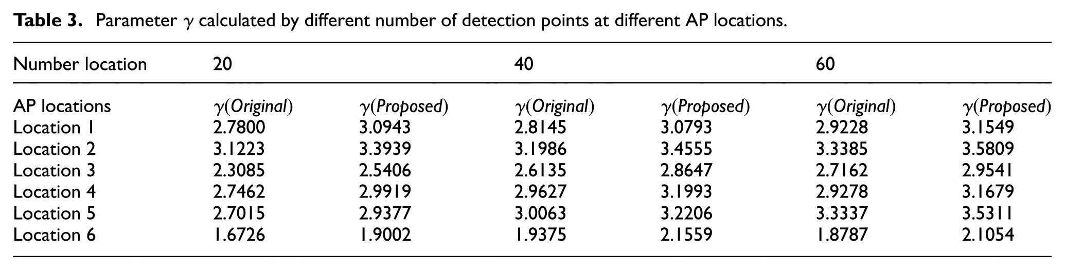
It can be seen from Table 3 that at the same AP location, the number of detection points is different, and the calculated parameter
The calculation method of the original path loss model parameters and the proposed path loss model parameters are, respectively, used. The RSS ranging algorithm based on trilateral localization, 15 the RSS ranging algorithm based on the least squares, 16 and the RSS ranging algorithm based on the particle swarm optimization 18 are calculated by arbitrarily selecting the locations of six different target APs in the region to be located, and analyzing the influence of the number of detection points on the localization algorithm. The experimental results are shown in Figures 11–13.

Influence of different number of detection points on trilateral localization algorithm.

Influence of different number of detection points on the least squares algorithm.

Influence of different number of detection points on the particle swarm optimization algorithm.
In Figures 11–13, the horizontal axis denotes six AP locations arbitrarily selected in the region to be located, and the vertical axis denotes the localization error. As can be seen from the figure, localization errors obtained by using different detection devices are different and the same algorithm is used at the same AP location, so different detection devices will affect the localization result. It can also be seen from the figure that the calculation method using the path loss model parameters proposed in this article is more accurate than the calculation method using the original path loss model parameters.
Conclusion and future work
Aiming to solve the problem that the existing Wi-Fi APs localization algorithm based on RSS ranging has lower localization accuracy, an indoor Wi-Fi APs localization algorithm based on improved path loss model parameter calculation method and recursive partition is proposed in this article. The algorithm recursively partitions the region where the target Wi-Fi APs are located, and partitions it into same sub-grids in turn until the sub-grids reach the set threshold. The RSS values from the detection points to the target AP are measured at the center of the grids, and the parameters in the path loss model are calculated by using the RSS differences. The distances between the detection points and the target AP are calculated by using the RSS values. Finally, the location of the target AP is estimated by executing localization algorithm. The experimental results show that the localization accuracy of the proposed algorithm is higher than the existing Wi-Fi AP localization algorithm based on RSS ranging, but it is affected by the location of AP, the different detection devices, and the number of detection points. In the future work, we will continue to study the exact relationship between RSS and actual distance and hope that the research can accurately and quickly find the location of the target Wi-Fi AP.
Footnotes
Handling Editor: Antonio Lazaro
Declaration of conflicting interests
The author(s) declared no potential conflicts of interest with respect to the research, authorship, and/or publication of this article.
Funding
The author(s) disclosed receipt of the following financial support for the research, authorship, and/or publication of this article: The work presented in this article is supported by the National Key R&D Program of China (No.2016 YFB0801303, 2016QY01W0105), the National Natural Science Foundation of China (No.U1636219, 61602508, 61772549, U1736214, 61572052), Plan for Scientific Innovation Talent of Henan Province (No.2018JR0018), and the Key Technologies R&D Program of Henan Province (No.162102210032).