
Abstract
Human wrist proprioception is particularly important due to its role in manual dexterity and associated tasks of daily living. Most studies have focused on testing single degree of freedom joints or were only capable of displacing or moving a joint in a single plane, such as flexion/extension of the wrist. The purpose of this study was to examine the effects of both direction and angular level on the accuracy of human wrist position reproduction error. Sixty subjects (all males) without a history of wrist pathology were recruited from a university campus. Subjects performed a position reproduction task in eight directions at three angular levels. The results showed that wrist position reproduction error depends on direction and angular level. Comparable reliability for the intra-observer measurements for wrist range of motion and joint position sense. The orientation of the joint position sense production ellipse is similar to the orientation of the range of motion ellipse, indicating that subjects generated the most accurate in directions where it is easy to generate more range of motion and the lowest accurate in directions where it is not easy to generate more range of motion. Joint position sense decreased in accuracy as the joint angle increased. The position reproduction error depends on the angular level, and subjects overshoot the target angle for the low angular levels (25% range of motion) and undershoot the target angle for high angular levels (75% range of motion). Mapping the human wrist joint position sense ellipse contributes to our understanding of the comprehensive proprioceptive function of the wrist. This technique offers the opportunity to assess all of the directions of proprioceptive function, which in turn may aid in improving therapeutic approaches.
Keywords
Introduction
Proprioception is critical for accurate movement, allowing the body to deliver afferent information from its periphery to the central nervous system (CNS) in order to maintain postural status, joint position sense (JPS), and overall position in space. Conscious proprioceptive senses can be subdivided into three categories: kinesthesia, JPS, and sense of resistance or force.1,2 JPS is defined as the ability to accurately reproduce a specific joint angle and is influenced by both muscle command 3 and muscle conditioning. 4
Human wrist proprioception is particularly important due to the role it plays in manual dexterity and associated tasks of daily living. 5 Accurate assessment of wrist joint function is very important for establishing strategies to maximize functional potential and evaluating the treatment and progression of disease. 6 The functional consequences of impaired wrist proprioceptive ability relate to the precise dynamic or static control of goal-directed arm movements. 7
At present, there is no established objective method for clinical assessment, and even though clinical rating scales such as the static and dynamic up–down test,8,9 a similar dual-joint position test, 10 and the Rivermead Assessment of Somatosensory Performance 11 are available and currently in use, they can provide only qualitative information and have low resolution.12,13
Over the past few years, several models of quantitative assessment have been proposed to investigate different aspects of proprioception. Some use the combinations of simple passive apparatuses restraining the movements to specific planes and matching paradigms with protractor scales14–16 to provide quantitative outcome measures. The robotic approaches to assess proprioception have also increased over the last few years, as they can take advantage of the control and sensing capabilities of robotic technology 17 to address requirements for an optimal assessment, such as high resolution, high reproducibility, and good control over stimuli. But expensive robotic devices are difficult to use in clinical settings. 18
Inertial and magnetic measurement systems (IMMS) are a new generation of motion analysis systems that have been used in studies to measure the three-dimensional (3D) orientation of body segments and joint angles. An IMMS consists of one or more sensing units (SUs), which integrate an inertial measurement system composed of one 3D accelerometer, one 3D gyroscope, and a 3D magnetometer. Data supplied by the accelerometer, gyroscope, and magnetometer are combined through sensor-fusion algorithms19,20 to measure the 3D orientation of the SU’s system of reference (SoR)—defined based on the sensing axes of the inertial and magnetic sensors—with respect to an earth-based SoR. 21 Some studies performed with IMMS have shown good intra- and inter-observer agreement.21–26
Up to this point, many studies have investigated the JPS of the wrist. However, most of these studies have focused on testing single DoF joints or were only capable of displacing or moving a joint in a single plane, such as flexion/extension of the wrist.27–33 There are some studies that have assessed proprioceptive function across the three degrees of freedom (DoF) of the wrist/hand complex.12,25,34 This is restrictive in that it only provides partial information on the proprioceptive status of a joint. However, it is clinically relevant to examine proprioceptive function for all of the directions of a given joint or limb system.21,35 Due to the lack of research focusing on the variety of testing protocols used, further study is needed to better understand JPS for all of the directions of the wrist.
To our knowledge, no research reported the relationship between human wrist JPS and directional and angular levels. It is necessary to understand what factors affect the accuracy of position sense and how it changes in response to conditions such as direction and angular level. The aims of the study were to examine wrist joint proprioceptive acuity using IMMS. Specifically, we applied a wrist joint position matching task to determine JPS for different directions and angular levels.
Methods
Subjects
Sixty subjects (all males, age 19.7 ± 0.6 years, 64.5 ± 5.8 kg, 169.8 ± 3.1 cm, all right-handed) were tested. Subjects self-reported their hand dominance by indicating with which hand they write. Exclusion criteria included the following: (1) a long-standing history of highly skilled motor activity, such as playing a musical instrument or basketball; 28 (2) prior wrist surgery; and (3) the presence of wrist pain or pathology. Subjects were briefed on the purpose of the study and experimental procedure, and completed the informed consent form. This study was approved by the institutional ethics review board of Renmin University of China.
Apparatus
The joint position sense measuring system (JPSS) (Kjyl Technologies, Beijing Kangjian Medical Devices Co., Ltd., CHN) is an IMMS consisting of one SU connected via Bluetooth to a computer for data processing and data storage that is worn on the belt. The sensor is small (38 mm × 53 mm × 21 mm), lightweight (30 g), and ambulatory (i.e. they can be used everywhere at any time and are not restricted to a certain measurement volume in a laboratory). In Figure 1, given this 3D orientation, a JPSS, which is attached to the wrist, was used to estimate the joint angles of the wrist. For correct positioning, a line was positioned from the midpoint of the wrist to the fingertip of the index finger. The base of the wireless JPSS sensor was positioned over the flat surface of the wrist dorsum, with the lower edge along this line and away from the wrist. For the present study, the JPSS sampling frequency was fixed to 100 Hz. Based on the JPSS, we developed a protocol that measures the JPS of the wrist.

Orientation of the SU’s SoR with respect to an earth-based SoR is provided as an output.
Protocol
The study was performed in a room that provided a quiet environment to assure proper concentration. 36 Subjects sat in a chair approximately 60 cm in front of a 16-in. LCD monitor secured with restraining straps across the midriff. Elbows were then positioned at shoulder height on an adjustable padded brace. The brace was secured in the optimum height position to produce a 90 degree angle between the upper arm and the forearm. The forearm was firmly strapped to the brace to ensure repeatability of wrist positioning across different trials and to avoid joint misalignment (slippage) during the experiment. 24 The JPSS was attached to the subject’s hand via a padded, non-elastic strap. The test hand was placed in a pronated position, and participants were asked to maintain this same arm configuration throughout the testing period. Participants were able to view their wrist position output on a 16-in. computer monitor.
The JPSS was used to record data during experimental trials. The range of motion (ROM) test program and JPS test program were coded using C++ software. 37
ROM test
Subjects moved their wrist in flexion until reaching their full ROM and then rotated their wrist counterclockwise in a circle, always maintaining the full ROM.
Data (ψ, θ) were recorded by the JPSS during experimental trials, where ψ is the angle in the ulnar/radial deviation axis, and θ is the angle in the flexion/extension axis. (Mψ2, 0) was recorded as the maximal angle on a radial deviation axis (direction 2) when ψ < 0, and |θ| was the minimum value. (0, Mθ4) was recorded as the maximal angle on the flexion axis (direction 4) when θ < 0, and |ψ| was the minimum value. (Mψ6, 0) was recorded as the maximal angle on the ulnar deviation axis (direction 6) when ψ > 0, and |θ| was the minimum value. (0, Mθ8) was recorded as the maximal angle on the extension axis (direction 8) when θ > 0, and |ψ| was the minimum value. (Mψ1, Mθ1) was recorded as the maximal angle in direction 1, which forms an angle of 45° with the extension axis when ψ < 0 and θ > 0, and ||ψ| – |θ|| was the minimum value. (Mψ3, Mθ3) was recorded as the maximal angle in direction 3, which forms an angle of 135° with the extension axis when ψ < 0 and θi < 0, and||ψ| – |θ|| was the minimum value. (Mψ5, Mθ5) was recorded as the maximal angle in direction 5, which forms an angle of −135° with the extension axis when ψ > 0 and θi < 0, and||ψ| – |θ|| was the minimum value. (Mψ7, Mθ7) was recorded as the maximal angle in direction 7, which forms an angle of −45° with the extension axis when ψ > 0 and θ > 0, and||ψ| – |θ|| was the minimum value. (Mψ9, Mθ9) was recorded as the maximal angle in the radial deviation axis when ψ was the maximum value. (Mψ10, Mθ10) was recorded as the maximal angle in the ulnar deviation axis when ψ was the minimum value. (Mψ11, Mθ11) was recorded as the maximal angle in the extension axis when θ was the maximum value. (Mψ12, Mθ12) was recorded as the maximal angle in the flexion axis when θ was the minimum value (Figure 2). This trial was repeated three times.

where
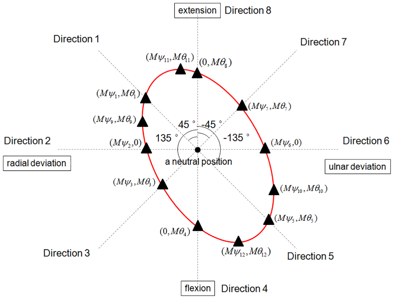
A schematic representation of an ellipse that represents movement tracking of the wrist, shown in red. The black triangles indicate ROM values in that direction. Directions 2, 4, 6, and 8 are the radial deviation, flexion, ulnar, and extension deviation, respectively. The angle between every two adjacent directions is 45°.
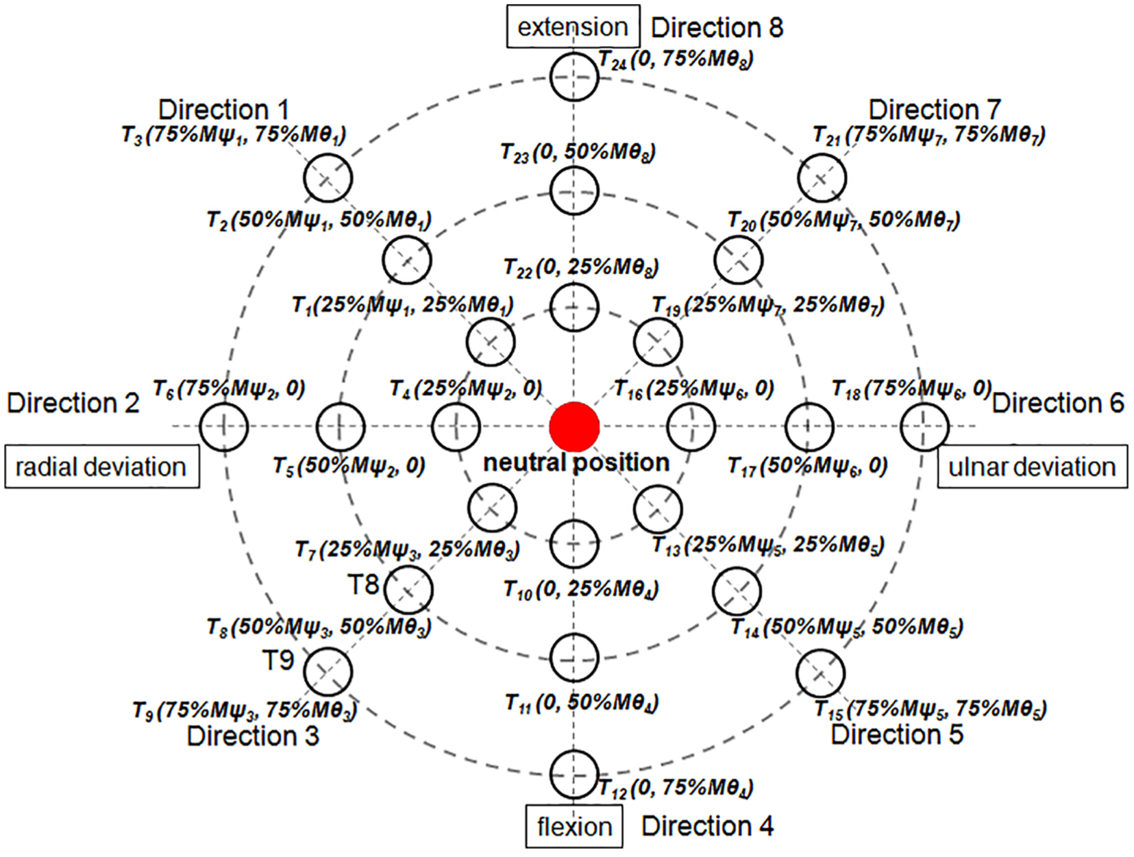
To describe the ROM in all of the directions, ellipses were fitted through ROM measurements for all data together. To fit the ellipse to the data, we used “Direct Ellipse Fit” 38 fitting to find a set of parameters for the general quadratic equation to minimize the distance between the data points and the ellipse (see equation (5))

Orientation of the major axis

Location of the center of the ellipse

Semi-major axis

Semi-minor axis

JPS test
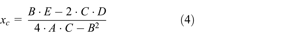
The testing protocol was thoroughly explained to subjects while they watched the visual output on a computer monitor. 39 A screen with a black circle was presented to subjects, via custom-written C++ software. The black circle represented the target position for a given trial. On the screen, an arrow appeared to prompt subjects as to which direction to move their arm to arrive at the target position. A red dot then appeared on the screen, representing the instantaneous wrist position (Figure 3). All trials began with the wrist in the neutral position. Subjects were instructed to move their wrist until the red dot on the screen was inside the black circle (when the actual wrist position was within 0.5° of the target position), indicating that the wrist was in the targeted position. Once the wrist was in the target position for 1 s, an audible beep was heard, and the screen turned black and remained so for the remainder of the trial. Subjects were instructed to maintain their wrist in the target position for 3 s, during which time they were to concentrate only on the position of the wrist. After the subject maintained the target position for 3 s, a computer-generated voice instructed subjects to relax, at which time the subject moved the wrist back to a neutral position.
A schematic representation of the computer output seen through the monitor display guiding the subject to the target position. The red dot indicates the instantaneous wrist position, and the black circles indicate the targeted position in eight directions at three angular levels.
Three seconds later, subjects attempted to replicate the target position. When subjects perceived that the wrist was at the target position, they used the contralateral hand to push a trigger button interfaced with the computer to time-stamp the reproduced position. Subjects were instructed to maintain their wrist in the reproduced position for 1 s after pushing the trigger button, while data for the i-position and j-trial were recorded as
Twenty-four target positions
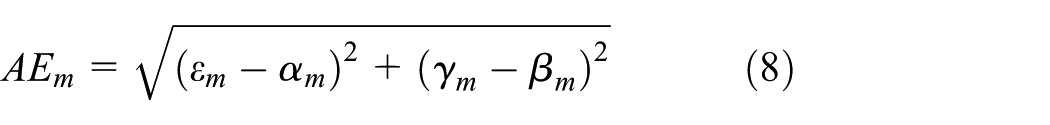
There were three dependent variables for JPS errors: absolute error (AE),40–44 constant error (CE),4,45–48 and variable error (VE).49–51 While AE is an assessment of overall error, CE reflects the directionality of errors and VE is the variability of the error over a series of trials and represents the accuracy of the performance.


where
To fit the ellipse to the data (
To evaluate the reliability and measurement precision of the JPSS, measurements were performed on two different days (session 1 and session 2) by two different experienced testers. 25
Data analysis
To quantify test–retest reliability, the intraclass correlation coefficient (ICC) was calculated for two sessions.52,53 ICC estimates were based on a single-measurement, absolute-agreement, two-way mixed-effects model. 54 The evaluation criteria and accepted standards for ICC values were outlined as follows: 0.00 to 0.39, poor; 0.40 to 0.74, fair; and 0.75 to 1.00, good. 55 A paired t-test was performed to identify systematic differences between the two sessions. 56
Two 8 × 3 repeated-measures analyses of variance were used to assess the effect of direction (directions 1, 2, 3, 4, 5, 6, 7, and 8) and angular level (25% ROM, 50% ROM, and 75% ROM) on AE, CE, and VE. 57 Follow-up comparisons were performed when appropriate using a Bonferroni adjustment for multiple comparisons.
Correlations between the ROM in different directions were assessed by Pearson’s correlation analysis. Statistical analysis was performed using IBM SPSS Statistics, version 20, software (IBM Corporation, Armonk, NY, USA). All data are provided as the M±SD. The level of statistical significance was set at p < 0.05.
Results
Reliability of the JPSS
Table 1 shows the test–retest reliability results for the 12 variables in the ROM test. Paired t-test results found no significant differences between the two sessions. Test–retest reliability between the two sessions exhibited a fair to excellent correlation, with ICCs ranging from 0.80 to 0.93.
Test–retest reliability results of the wrist ROM test (°).

ROM: range of motion; ICC: intraclass correlation coefficient.
p < 0.05; **p < 0.01.
Table 2 shows the test–retest reliability results for the 24 variables in the JPS test. Paired t-test results found no significant differences between the two sessions. The test–retest reliability between the two sessions exhibited a fair to excellent correlation, with ICCs ranging from 0.76 to 0.91.
Test–retest reliability results of the wrist joint position sense test (°).

ICC: intraclass correlation coefficient.
p < 0.05; **p < 0.01.
ROM of the wrist
The maximum ROM was 68.6°± 6.1°, and the minimum ROM was 26.2°± 5.8° (see Table 3).
ROM of the wrist in different directions (°).

ROM: range of motion.
For the ROM test trials, an ellipse was found, indicating that the ROM differs in all of the directions, with the major axis of the ellipse as the maximum ROM direction. In Figure 4, the greater the distance from the center of the graph, the greater is the ROM. Black triangles show mean ROM values in that direction over subjects. An ellipse was fitted through these data, shown in red. The general elliptical shape of the data is very apparent.

ROM data with fitted ellipses, showing a polar view of the ROM at different directions. Black triangles indicate mean ROM values in that direction across subjects.
The parameters of the ellipse fitted to the complete dataset were as follows: A = −0.0007727, B = −0.0005416, C = −0.0003450, D = 0.0108721, and E = 0.0027005. The orientation of the major axis (least accurate direction) was as follows: θ = 25.8°. The location of the center of the ellipse was as follows: xc = 7.8° and yc = −2.2°; semi-major axis: a = 68.3°; and semi-minor axis: b = 41.0°.
JPS of the wrist
AE
There was no significant interaction observed between direction and angular levels: F = 1.26 and p = 0.23. A significant main effect was found for direction, F = 6.21 and p = 0.01, indicating that the JPS differs between direction 1 (M = 3.2°, SD = 0.6), direction 2 (M = 3.0°, SD = 0.5), direction 3 (M = 3.7°, SD = 0.7), direction 4 (M = 4.2°, SD = 0.7), direction 5 (M = 3.7°, SD = 0.7), direction 6 (M = 3.4°, SD = 0.7), direction 7 (M = 4.4°, SD = 0.9), and direction 8 (M = 3.5°, SD = 0.6). The results showed the JPS at directions 1, 2, and 6 to be significantly more accurate than for other directions, p < 0.05, and the JPS at directions 3, 4, and 7 to be significantly less accurate than for other directions, p < 0.05. The major axis of the ellipse was the least accurate direction. In Figure 5, the greater the distance from the center of the graph, the less accurate are the results. Black X signs indicate mean JPS values in that direction over subjects. An ellipse was fitted through these data, shown in blue. The general elliptical shape of the data is very apparent.

Position reproduction error with fitted ellipses, showing a polar view of the JPS at different directions. Black X signs indicate mean JPS values in that direction across subjects.
The parameters of the ellipse fitted to the complete dataset were as follows: A = −0.0918048, B = 0.0266083, C = −0.0624640, D = 0.0531735, and E = −0.0227221; the orientation of the major axis (least accurate direction) was as follows: θ = −21.1°; the location of the center of the ellipse was as follows: xc = 0.3° and yc = −0.1°; semi-major axis: a = 4.2°; and semi-minor axis: b = 3.8°.
The orientation of the JPS production ellipse (blue) was similar to the orientation of the ROM ellipse (red) (the direction of the major axis of the JPS production ellipse is similar to the direction of the minor axis of the ROM ellipse) (Figure 6).

Ellipses fitted to normalized ROM (red) and JPS (blue) data across subjects. Black triangles indicate mean ROM values in that direction across subjects. Black X signs indicate mean JPS values in that direction across subjects.
There was a significant main effect found for angular level, F = 26.97 and p = 0.01. Follow-up t-tests were performed with a Bonferroni adjustment for multiple comparisons. The results showed the JPS at 25% ROM (M = 3.0°, SD = 0.8) to be significantly more accurate than 50% ROM (M = 3.8°, SD = 0.5) and 75% ROM (M = 4.2°, SD = 0.5), p = 0.01. AE decreased in accuracy as the angular level increased (Figure 7).

AE, an assessment of the position reproduction overall error, as a function of angular levels. The red squares indicate mean AE values across subjects.
CE
CE in the ulnar/radial deviation axis
The interaction between direction and angular level was not significant, F = 1.28 and p = 0.21. There was no significant main effect found for direction, F = 1.27 and p = 0.27. However, there was a significant main effect found for angular level, F = 8.27 and p = 0.01. A significant difference was found between 25% ROM (M = 0.4°, SD = 0.1), 50% ROM (M = −0.1°, SD = 0.1), and 75% ROM (M = −0.4°, SD = 0.2), p = 0.01.
CE in the flexion/extension axis
The interaction between direction and angular level was not significant, F = 1.07 and p = 0.38. There was also no significant main effect found for direction, F = 1.907 and p = 0.069. There was a significant main effect found for angular level, F = 3.98 and p = 0.02. A significant difference was found between 25% ROM (M = 0.5°, SD = 0.2), 50% ROM (M = −0.1°, SD = 0.2), and 75% ROM (M = −0.2°, SD = 0.1), p = 0.01. In Figure 8, the blue triangles indicate mean CE values in the ulnar/radial deviation axis across subjects, and the red circles indicate the mean CE values in the flexion/extension axis across subjects.
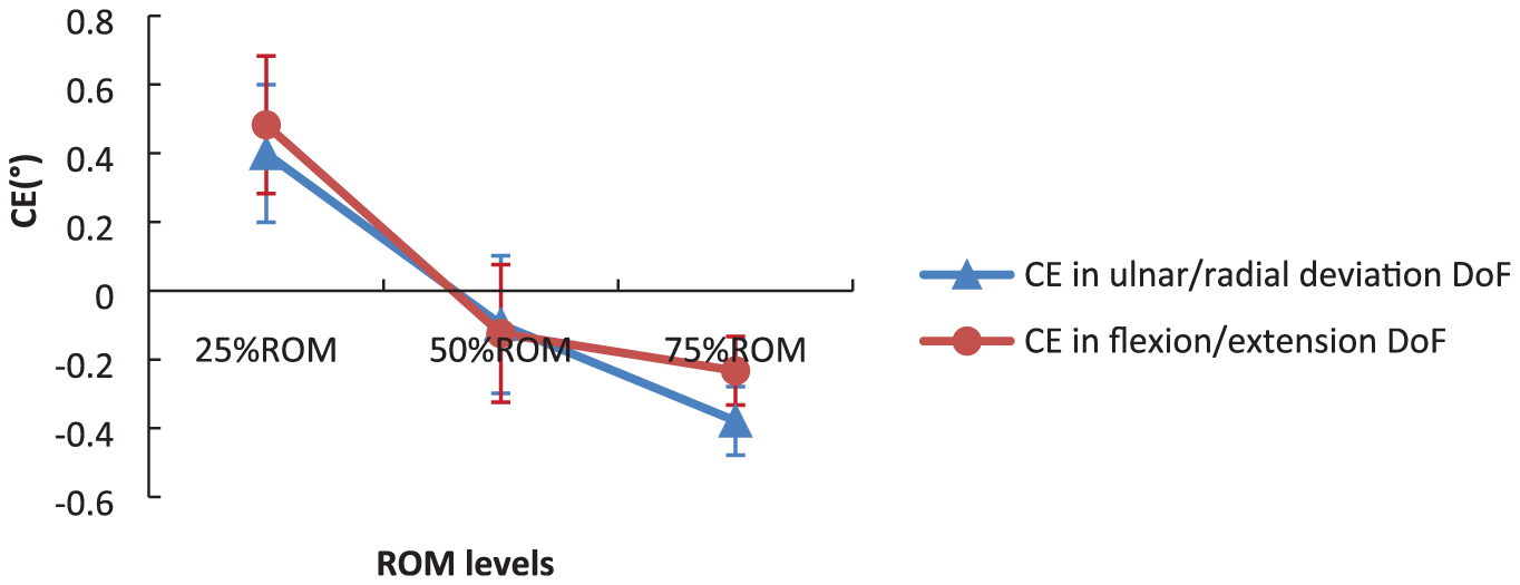
CE, the position of reproduction directionality of error, as a function of angular levels.
VE
There was no significant interaction observed between direction and angular levels, F = 1.56 and p = 0.08. A significant main effect was found for direction, F = 2.51 and p = 0.02, indicating that the JPS differs between direction 1 (M = 2.5°, SD = 0.7), direction 2 (M = 2.4°, SD = 0.8), direction 3 (M = 2.6°, SD = 0.6), direction 4 (M = 2.9°, SD = 0.8), direction 5 (M = 2.9°, SD = 0.7), direction 6 (M = 2.7°, SD = 0.8), direction 7 (M = 3.1°, SD = 0.8), and direction 8 (M = 2.5°, SD = 0.7). The results showed the JPS at directions 1, 2, and 8 to be significantly more precisely estimated than for other directions, p < 0.05, and the JPS at direction 7 to be significantly less precisely estimated than for other directions, p < 0.05 (Figure 9).

VE, the variability of the error over a series of trials, represents the precision of the performance, as a function of direction.
A significant main effect was found for angular level, F = 17.65 and p = 0.01. Follow-up t-tests were performed with a Bonferroni adjustment for multiple comparisons. The results showed the JPS at 25% ROM (M = 2.2°, SD = 0.6) to be significantly more precisely estimated than 50% ROM (M = 2.9°, SD = 0.8) and 75% ROM (M = 2.9°, SD = 0.7), p = 0.01. AE decreased in accuracy as the angular level increased (Figure 10).

VE, the variability of the error over a series of trials, represents the precision of the performance, as a function of angular levels.
For this method to have any clinical usefulness, individual data were presented and compared against mean data (Figure 11).

(a) AE, (b, c) CE, and (d) VE of individual data and mean data, which represent the accuracy and precision of the performance, as a function of direction and angular levels.
Discussion
Reliability and precision of the JPSS
ICCs exhibited comparable reliability for both intra- and inter-observer measurements for wrist ROM and JPS, indicating that the reliability and precision of the wrist ROM and JPS measurement with the JPSS, as well as the current protocol, are not dependent on either the observer or day of measurement. Similar to our results, van den Noort found high ICCs within (intra) and between (inter) observers, especially for scapular retraction/protraction (ICC = 0.65–0.85) and medio/lateral rotation (ICC = 0.56–240.91).
JPS in different directions (human wrist JPS ellipse)
We have found the ROM for flexion/extension DoF to be 55.6°± 5.3°/58.7°± 4.4°, ulnar/radial deviation DoF is 41.1°± 5.1°/26.2°± 5.8°, and an average AE of reposition of a value from 3.0° to 4.2°. These results are similar to these data from other works of related topics (the ROM for flexion/extension DoF is 67.6°± 8.1°/71.0°± 9.6°, ulnar/radial deviation DoF: 44.3°± 8.2°/21.3°± 6.3°, 58 and the error of acuity for flexion/extension is 4.64°± 0.24°; abduction/adduction: 3.68°± 0.32°). 12
Both AE and VE depend on the directions. The direction of the major axis of the JPS reproduction ellipse was the least accurate direction, while the direction of the minor axis of the ROM ellipse was the least ROM direction. In addition, the direction of the minor axis of the JPS reproduction ellipse was the most accurate direction, and the direction of the major axis of the ROM ellipse was the greatest ROM direction, indicating that subjects generated the most accuracy in directions in which it was easy to generate more ROM and the lowest accuracy in directions where it was not easy to generate more ROM (Figure 6). VEs were calculated to represent the precision of JPS. Subjects generated more precise estimates in the radial deviation, extension, and the direction between radial deviation and extension, and less precise estimates in the direction between ulnar deviation and extension than for other directions.
It has been postulated that such directional differences may be due to asymmetries in motor performance, structural differences in wrist joints, antagonistic muscle mass, and the density and distribution of receptors. 59
It is possible that, for different directions, the combination of the muscles used may change or muscles may react differently, which could explain the effect on ROM and position reproductions in different directions. Immunohistochemical studies of wrist anatomy revealed a high distribution density of mechanoreceptors in the dorso-radial ligaments, such as the dorsal radiocarpal, dorsal intercarpal, and scapholunate interosseous; medium density in the volar and volar-triquetral; and a long radiolunate ligament nearly devoid of mechanoreceptors. The wrist ligaments were found to vary in innervation—the dorsal intercarpal (DIC), dorsal radiocarpal (DRC), and scapholunate interosseous (SLI) being richly innervated and the long radiolunate (LRL) being almost without innervation. The difference in innervation between the ligaments might indicate differences in function. Ligaments without innervation might act as structures of passive restraint, whereas ligaments with rich innervation are proposed to also provide proprioceptive information. Wrist ligaments vary with regard to sensory and biomechanical functions. Rather, based on the differences found in structural composition and innervation, wrist ligaments are regarded as either mechanically important ligaments or sensory ligaments. The mechanically important ligaments are ligaments with densely packed collagen bundles and limited innervation. They are located primarily in the radial, force-bearing column of the wrist. The sensory ligaments, by contrast, are richly innervated although less dense in connective tissue composition and are related to the triquetrum. The triquetrum and its ligamentous attachments are regarded as key elements in the generation of the proprioceptive information necessary for adequate neuromuscular wrist stabilization.60,61 There are more muscle spindles in muscles with larger cross-sectional areas,62,63 and wrist flexors have twice the volume of wrist extensors. 64 It has been hypothesized that wrist extension–directed movements stretch the wrist flexors, thereby activating muscle spindles, rendering them more easily detected than flexion-directed movements. 7 These differences in mechanoreceptor density and innervation might be responsible for the proprioceptive anisotropy reported in our previous investigation. 25
JPS in different angular levels
AE, CE, and VE depend on the angular level. JPS decreased in accuracy and precision as the angular level increased, and subjects overshot the target angle for the low angular levels (25% ROM) and undershot the target angle for high angular levels (75% ROM).
The means by which the reference joint angle is established also is an important factor to consider in tests of position matching ability. In one study, 20 healthy young adults were asked to match targets that were either 20° or 40° from the start elbow joint position. AEs were found to be, on average, 66% greater for the larger target amplitude. 65 One hypothesis that has been put forth to explain this finding is that the increased errors seen with larger target amplitudes reflect increased sensorimotor noise when movement requires an increased neural control signal. 66
It is possible that with increasing angular level, the contribution of joint receptors and skin receptors may change, which could explain the changing effect of angular level on position reproductions. Ferrell and Smith found that joint receptors provided positional information principally at the extremes of the normal range of joint movements, perhaps acting as limit detectors. 67 At more proximal joints, it appears that muscle afferents provide the major proprioceptive signals. It may be that joint input is more important than muscle afferent input at the extremes of the normal range of joint movements. 68 Joint rotation causes the skin on one side of the joint to be stretched while it is slackened or even folded on the other side. Such deformations stimulate skin mechanoreceptors. The sensitivity of human skin stretch receptors when expressed as impulses per degree of joint motion is similar to that of muscle spindle afferents.69,70 Skin receptors become activated by skin stretching as the angular level increases. It has been postulated that as joints approach the limits of their ROM, joint receptor and skin receptor information may bias perception of joint angles. 71
Conclusion
We here experimentally analyzed the influence of different directions and angular levels on the perception of human wrist position. The orientation of the JPS production ellipse is similar to the orientation of the ROM ellipse, indicating that subjects generated the most accuracy in directions in which it is easy to generate more ROM and the lowest accuracy in directions in which it is not easy to generate more ROM. JPS is one of the key components of proprioception that decreases in accuracy as the joint angle increases. The position reproduction error depends on the angular level, and subjects overshoot the target angle for the low angular levels (25% ROM) and undershoot the target angle for high angular levels (75% ROM). While mapping the human wrist joint position, sense ellipse contributes to our understanding of the comprehensive proprioceptive function of the wrist. This technique offers the opportunity to assess all of the directions of proprioceptive function, which in turn may aid in improving therapeutic approaches.
Footnotes
Handling Editor: Joel Rodrigues
Declaration of conflicting interests
The author(s) declared no potential conflicts of interest with respect to the research, authorship, and/or publication of this article.
Funding
The author(s) disclosed receipt of the following financial support for the research, authorship, and/or publication of this article: The authors would like to acknowledge the support of the National Social Science Fund of China (BLA160071).