
Abstract
Teleoperation is of great importance in the area of robotics especially when people’s presence at the robot working space is unavailable. It provides an alternative to employ human intelligence in the control of the robot remotely. We establish robotic teleoperation systems with a wearable multimodal fusion device. The device is integrated with 18 low-cost inertial and magnetic measurement units, which cover all segments of the arm and hand. The multimodal fusion algorithm based on extended Kalman filter is deduced to determine the orientations and positions of each segment. Then, the robotic teleoperation systems using the proposed device are designed. The novel teleoperation schemes can be applied for 11DOF robotic arm–hand system and 10DOF robotic arm–hand system, in which the operator’s fingers are used for robotic hand teleoperation, and the arms with palm are used for robotic arm teleoperation. Meanwhile, the proposed robotic teleoperation systems are fully realized with a user-friendly human–machine interaction interface. Finally, a series of experiments are conducted with our robotic teleoperation system successfully.
Keywords
Introduction
The robotic teleoperation provides an alternative to employ human intelligence in the control of the robot remotely. Human intelligence is used to make a decision and control the robot especially when it is in unstructured dynamic environments. It is very useful in situations where people’s presence in the working space is unavailable, for example, in nuclear power plants, in space, and at the bottom of the sea. It is promising that the robotic teleoperation will play a more significant role in a broader range of areas. In the robotic teleoperation, the robot accepts instructions from human operator far away through some sensors or control mechanism by a communicating network. Meanwhile, the robot sends its status and environment information to the human operator as feedback. Only the efficient interaction between the robot and the human operator can make the robotic teleoperation system to perform well. There are a variety of human–machine interfaces for robotic teleoperation system. Joysticks, dials, and robot replicas are commonly used. 1 However, for completing a teleoperation task, these traditional mechanical devices always require unnatural hand or arm motion. Recently, with the rapid development of the motion sensors and vision-based technique, it is believed to provide a more natural and intuitive alternative for robotic teleoperation.
Vision-based teleoperation is easy for visual systems to capture contours of the human, but the captured images cannot provide enough information to track hands in the three-dimensional space. It is because the derivation of the spatial position information will lead to multiple 2-D–3-D mapping solutions. The well-developed red-green-blue-depth (RGBD) camera has been widely used in robotic systems nowadays. 2 This camera consists of a laser projector and a Complementary Metal Oxide Semiconductor (CMOS) sensor, which enables the sensor to monitor 3-D motions. 3 Du et al. 4 and Alfaiz and Shanta 5 successfully applied the Kinect sensor to teleoperate the robotic manipulator. However, the vision-based system is often affected by varying light conditions, changing backgrounds, and a large clutter. This makes extracting relevant information from visual signals difficult and computationally intensive. Furthermore, the occlusion of fingers results in a nonobservable problem that leads to a poor estimation of the hand pose. 6
Another popular way is developed with the device based on motion sensors. Inertial sensors, electromagnetic tracking sensors, electromyography sensors, leap motion devices, or gloves instruments with angle sensors are used to track the operator’s hand or arm’s motion for teleoperation. 7 –9 Especially, the inertial and magnetic sensors that are low cost, small size, compact, and low-energy consumption have been widely used. Miller et al. 10 developed the modular system for untethered real-time kinematic motion capture using inertial measurement units. It has been successfully applied in the system for the NASA Robonaut teleoperation. Kobayashi et al. 11 used inertial measurement units for the motion capture of the human arm, and the CyberGlove, CyberGlove Systems Inc., San Jose, CA , USA was utilized for the hand motion capture. The hand/arm robot is teleoperated according to the motion of the operator’s hand and arm. Du et al. 12 proposed a system which used a position sensor and an inertial measurement unit to track the operator’s hand and then controlled the robot with the obtained orientation and position of the hand. This method is more effective for the operator to focus on the manipulation task instead of thinking which gesture should be used. It can be seen that the multimodal sensing information is widely used in the robotic teleoperation system with the development of sensing technology. However, inertial and magnetic sensing–based motion capture device that can simultaneously capture the motion of both the arms, the hands, and fingers is never presented in the previous research work.
This article deals with the teleoperation systems for two hand/arm robots with different degrees of freedom (DOF) using a multimodal wearable device. The device is comprised of inertial and magnetic sensors. The multimodal fusion algorithm is deduced to determine the orientations and positions of the gestures. It can accurately and fully capture the fine gesture and as a multiple input device to inform the operator with more precise information from the remote site. The novel teleoperation schemes for two kinds of robotic systems are presented. And the experiments are designed and implemented to prove the validness of the proposed systems. The article is organized as follows. “Multi-modal fusion algorithm for wearable device” section presents the designs of the wearable device, and the multimodal fusion algorithm is deduced for the fine motion capture. “Robotic teleoperation scheme” section describes the teleoperation schemes for the robotic systems. “Experiments and results” section reports the results of fine gesture capturing experiments and robotic teleoperation experiments. Conclusions are drawn in the fifth section.
Multimodal fusion algorithm for wearable device
In this section, the inertial-based wearable device is designed and the kinematics of the arm–hand is analyzed. Then, the multimodal fusion algorithm is deduced to determine the orientations and positions of the arm–hand.
Wearable device design
Human arm–hand system can be approximated as the rigid body parts. These segments are upper arm, forearm, palm, and five fingers, which are connected by different joints, as shown in Figure 1. The kinematic chain of the arm that this model produces consists of seven DOFs. Shoulder is modeled as a ball and socket joint with three DOFs, elbow is modeled as a rotating hinge joint with two DOFs, and wrist is also modeled as a rotating hinge joint with two DOFs. The human hand model has 20 kinematic DOFs. The distal interphalangeal and proximal interphalangeal (PIP) joints of each finger have one DOF, while the metatarsophalangeal joints have two DOFs. The third DOF of the trapeziometacarpal joint allows the thumb to rotate longitudinally as it is opposite to the fingers. According to the above descriptions, 18 sensor modules should be used to capture the motions of all the segments of human arm–hand.

The model of the human arm–hand.
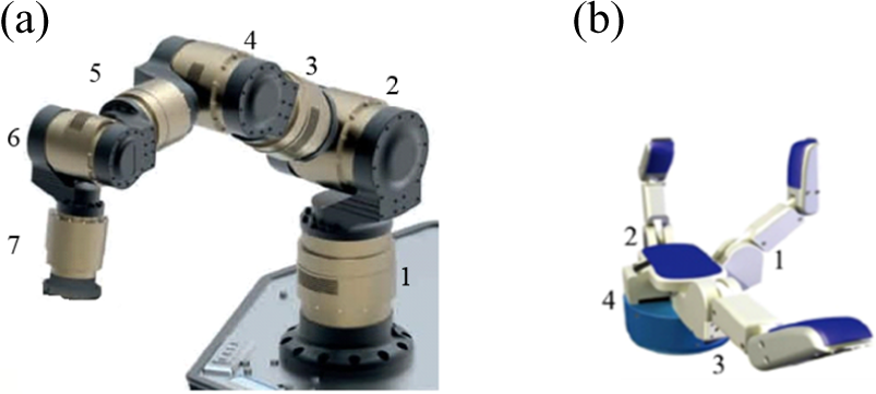
The wearable device comprises 18 inertial and magnetic measurements, and each is placed on the segments of human arm–hand. There are six strings, and each string deploys three inertial and magnetic measurement units (IMMUs). Five of them are used to capture the motions of the five fingers, and the other one is used to capture the motions of the palm, upper arm, and forearm. The battery and Microcontroller Unit (MCU) are attached to the wrist. The design of the wearable device is shown in Figure 2. The proposed wearable device is designed based on the low-cost IMMUs, which can capture more information of the motion than the traditional sensors. The traditional sensors used in data glove like fiber or hall effect sensors are frail. Nevertheless, the board of inertial and magnetic sensor is an independent unit and it is more compact, durable, and robust. Moreover, the proposed wearable device cannot only capture the motion of hand but also capture the motion of arm, and the estimated results of motion are outputting in real time.

The design of the wearable device.
Multimodal fusion algorithm
There are three kinds of modal in the IMMU, two independent ways can determine the orientations. One is obtained from open-loop gyros. The orientations are obtained by the open-loop integration process of angular velocity, which has high dynamic characteristic. However, the gyro errors would create wandering attitude angles and the gradual instability of the integration drifting. The other way is determined from open-loop accelerometers and magnetometers. The orientations can be correctly obtained from accelerometers and magnetometers in the ideal environment. But the results would lead to large errors and lose reliability in high dynamic conditions. The independent ways are both quite difficult to achieve acceptable performance. Multimodal fusion is the great choice to attain the stable and accurate orientations. Then the fusion algorithm will be deduced.
In application of inertial and magnetic sensors, two coordinate frames are setup: the navigation coordinate frame and the body frame are fixed to the rigid body. The orientation of a rigid body in space is determined when the axis orientation of a coordinate frame attached to the body frame is specified with respect to the navigation frame. The model of the arm–hand and the frames of each IMMU are shown in Figure 3. Among the fingers, the middle finger is used in the model, which is a simplified six-bar linkage mechanism. The global frame is set in the shoulder, and the local reference frames are located in each IMMU, respectively. The global reference frame Z-axis is defined along the axial axis (from the head to the feet) of the subject, the Y-axis along the sagittal (from the left shoulder to the right shoulder) axis, and the X-axis along the coronal axis (from the back to the chest). The local frame z-axis is defined along the axial axis (normal to the surface of IMMU along the downward) of the subject, the y-axis along the sagittal (from the left side to the right side of the IMMU) axis, and the x-axis along the coronal axis (from the back to the forward of IMMU). Meanwhile, two assumptions about data glove in use are made: (1) the body keeps static, just arm and hand are in motion and (2) the local static magnetic field is homogeneous throughout the whole arm.

The model and frames of the arm–hand.
According to the coordinate frames, the sensors’ models are setup as follows.

where
The magnetic field vector expressed in the navigation frame is supposed to be modeled by the unit vector

where
Based on the measured 3-D angular velocity, acceleration, and magnetic field of one single IMMU, it is possible to stably estimate its orientation with respect to a global coordinate system. The global coordinate N and each coordinate b of IMMUs are shown in Figure 1. The transformation between the representations, of a 3 × hcolumn-vector

where
The attitude matrix

where,
The state vector is composed of the rotation quaternion. The state transition vector equation is


where Ts denotes the sampling period of the measurements and the gyro measurement noise vector,
Then, the process noise covariance matrix Qk will have the following expression

The measurement model is constructed by stacking the accelerometer and magnetometer measurement vectors
The covariance matrix of the measurement model
where the accelerometer and magnetometer measurement noise
Because of the nonlinear nature of equation (8), the Extended Kalman Filter (EKF) approach requires that a first-order Taylor–Mac Laurin expansion is carried out around the current state estimation by computing the Jacobian matrix

Then, the orientations are estimated by the following EKF equations.
Compute the a priori state estimate

Compute the a priori error covariance matrix

Compute the Kalman gain

Compute the a posteriori state estimate

Compute the a posteriori error covariance matrix

According to the above algorithm, the absolute orientations of each IMMU can be estimated. Then, the kinematic models of the arm, hand, and fingers are considered to determine the orientations of each segment.
The kinematic frames of the arm, hand, and the forefinger are presented here. There are six joints, and the coordinate frames are built including the global coordinate (N), upper-arm coordinate (b 1), forearm (b 2), palm coordinate (b 3), proximal coordinate (b 4), medial coordinate (b 5), and distal (b 6). And the lengths between the joints are l 1, l 2, l 3, l 4, l 5, and l 6, as shown in Figure 3. Then, the relative orientations between two consecutive bodies can be determined as follows

where
Meanwhile, human arm–hand motion can be approximated as the articulated motion of rigid body parts. Thus, the kinematic chain that this model produces consists of 10 variables or DOFs: three in the shoulder joint, two in the elbow joint, two in the wrist joint, two in the proximal joint, one in the medial joint, and one in the distal joint. Hence, the responding constraints are used to determine the orientations of each segment.
Furthermore, the position of the palm

where the transformation between two consecutive bodies is expressed by
The total transformation

where
Robotic teleoperation scheme
The teleoperation of anthropomorphic robotic system is generated by a large numbers of involved DOF, for example, up to 11 for the case of a seven DOF arm plus four of a hand with three fingers. Therefore, the most intuitive way to command these robots is to capture the movements of a human operator and map them to the robotic system. But the kinematic structure of robots is different from that of the operator. Hence, the approach that the mapping of the sensorial information obtained from the operator movements onto the movement space of the devices is important. Three methods have been commonly used for kinematic mapping. They are joint angle mapping (joint-to-joint mapping), 13 pose mapping, 14 and position mapping (point-to-point mapping). 15 Joint-to-joint mapping is that each sensor of the operator movements is directly associated with a joint of the robot. Pose mapping is that each pose of the operator is associated with a predefined pose of the robot. Point-to-point mapping is that the positions of particular points of the operator arm or hands are replicated by predefined points on the robot.
In this section, we deal with the problem of teleoperating two robotic hand–arm systems by the wearable device and present the implementation of different teleoperation schemes, including the teleoperation of the robotic arms and the robotic hand.
11DOF robotic teleoperation system
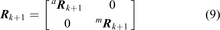
The 11DOF robot consists of a seven DOF robotic arm and a four DOF dexterous robotic hand. The robotic arm (Figure 4(a)) is produced by SCHUNK, Germany, with seven force–torque modules that can rotate around its axis. The orders of the modules of the robotic arm is one to seven from base to the end joint. The three-fingered mechanical hand is made by Barrett (Figure 4(b)). The position of one finger usually called thumb is fixed and the other two can spread synchronously and symmetrically about the palm up to 180°. The spreading action allows for the hand to grasp objects varying from different sizes and shapes. Besides the spreading action, each of the three fingers has two coupled joints. Internally, the hand is of four DOF actuated by four motors. The orders of the motors is also shown in the Figure 4(b).
11DOF robotic arm–hand system. (a) SCHUNK robotic arm and (b) Barrett robotic hand. DOF: degrees of freedom.
The joint-to-joint mapping is used for the SHUNUK-Barrett robotic system. The movement information flow of the hand and arm is directly converted into the control instruction flow of the robotic hand–arm. Moreover, the robotic arm is teleoperated by the arm and hand, and the robotic hand is teleoperated by the fingers. The seven postures of the arm and hand is used that included three DOF for the shoulder, one DOF for the elbow joint, and two DOF for the wrist. These seven angles are respectively corresponding to the mechanical arm of the seven joints. Meanwhile, the robotic hand has only four DOF, so we only select the index finger, middle finger, and ring finger for the three fingers of the robotic hand. The second joints of the index finger, middle finger, and ring finger are respectively corresponding to the bending of the mechanical hand, and the opening angle of the index finger and middle finger is corresponding to the fourth rotation of the robotic hand. The mapping relationships are shown in Figure 5. The teleoperation scheme is based on the data packet received from the wearable device and the commands separately accepted by the robotic arm and robotic hand. A one to one relation between those two sets is established in such a way that a natural movement from the user is required. And specific commands are shown in Table 1.

Teleoperation scheme of 11DOF robotic system. DOF: degrees of freedom.
Mapping commands of 11DOF robotic teleoperation system.

DOF: degrees of freedom.
10DOF robotic teleoperation system
The 10DOF robot consists of a six DOF robotic arm and a four DOF dexterous robotic hand. The robotic arm is UR5. The orders of the joints of the robotic arm is one to six from base to the end joint as shown in Figure 6(a). The three-fingered mechanical hand is also Barrett robotic hand as shown in Figure 6(b).

10DOF robotic arm–hand system. (a) UR5 robotic arm and (b) Barrett robotic hand. DOF: degrees of freedom.
The pose mapping is used for the UR5 robotic arm. The pose of the IMMU on the palm is corresponded to the pose of the end pose of the robotic arm. The joint-to-joint mapping is also used for the robotic hand teleoperation. The teleoperation scheme is shown in Figure 7, and mapping relationships specific commands are shown in Table 2.

Teleoperation scheme of 10DOF robotic system. DOF: degrees of freedom.
Mapping commands of 10DOF robotic teleoperation system.

DOF: degrees of freedom.
Experiments and results
The motion capture experiments are implemented to investigate the accuracy and stability of the wearable device. Then, the real-time teleoperation experiments of 10DOF and 11DOF robotic system are developed to prove the validness of the proposed device.
Motion capture experiments
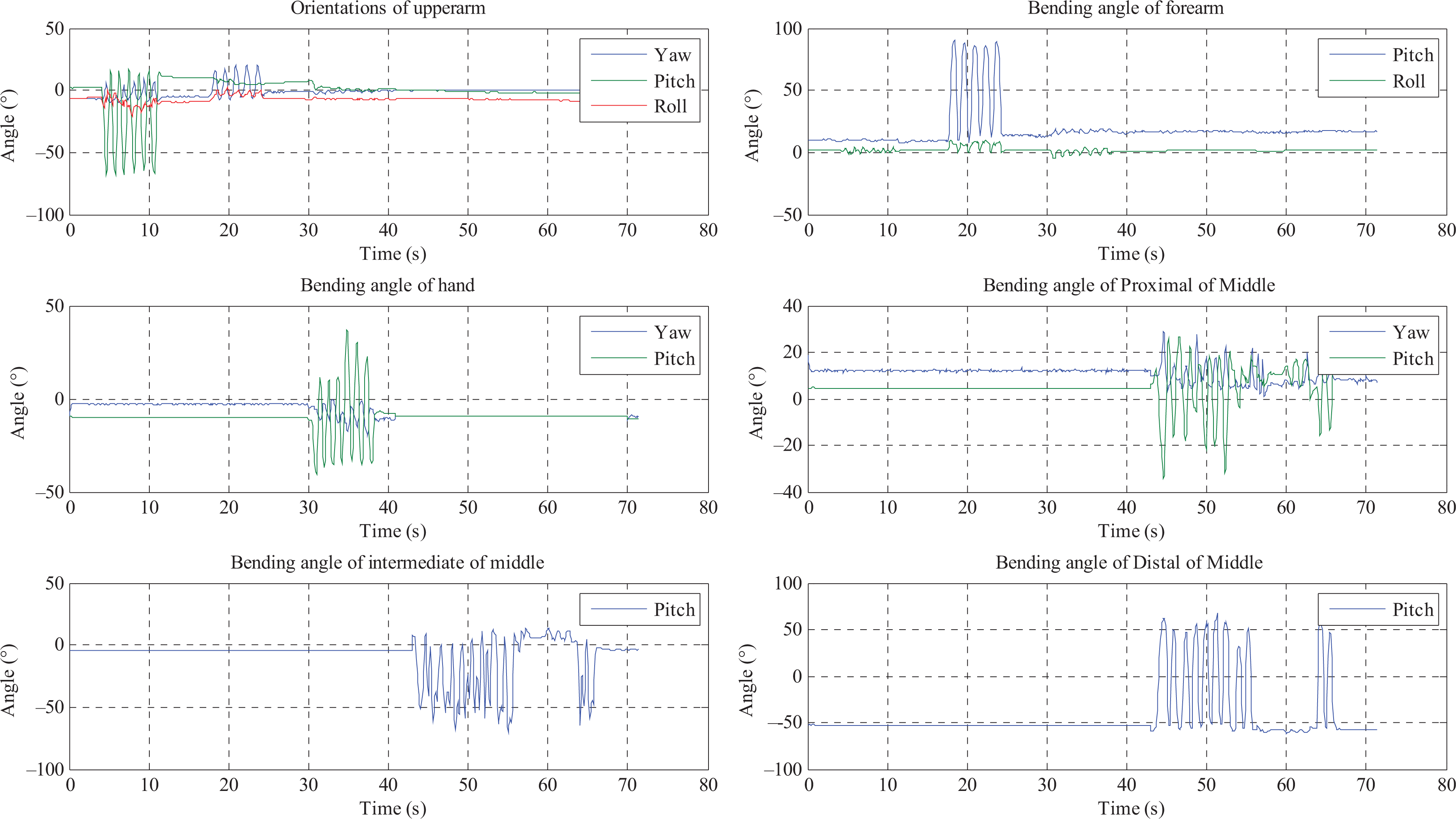
The wearable device is shown as Figure 8.The IMMUs’ data are sampled, collected, and computed by the MCU and subsequently transmitted via Bluetooth to the external devices. The MCU processes the raw data, estimates the orientations of each unit, encapsulates them into a packet, and then sends the packet to the PC by Bluetooth. The baud rate for transmitting data is 115,200 bps. The frequency is 50 HZ. Using this design, the motion capture can be demonstrated by the virtual model on the PC immediately. The interface is written by C#. To verify the effectiveness of orientation estimation algorithm, three orientations of the IMMUs are evaluated by the different situations. The results of six IMMUs, which are respectively on upper arm, forearm, palm, proximal of the middle finger, medial of the middle finger, and distal of the middle finger, are shown in Figure 9. The orientations of the gestures are shown in Figure 10, and the positions of the hand are shown in Figure 11.
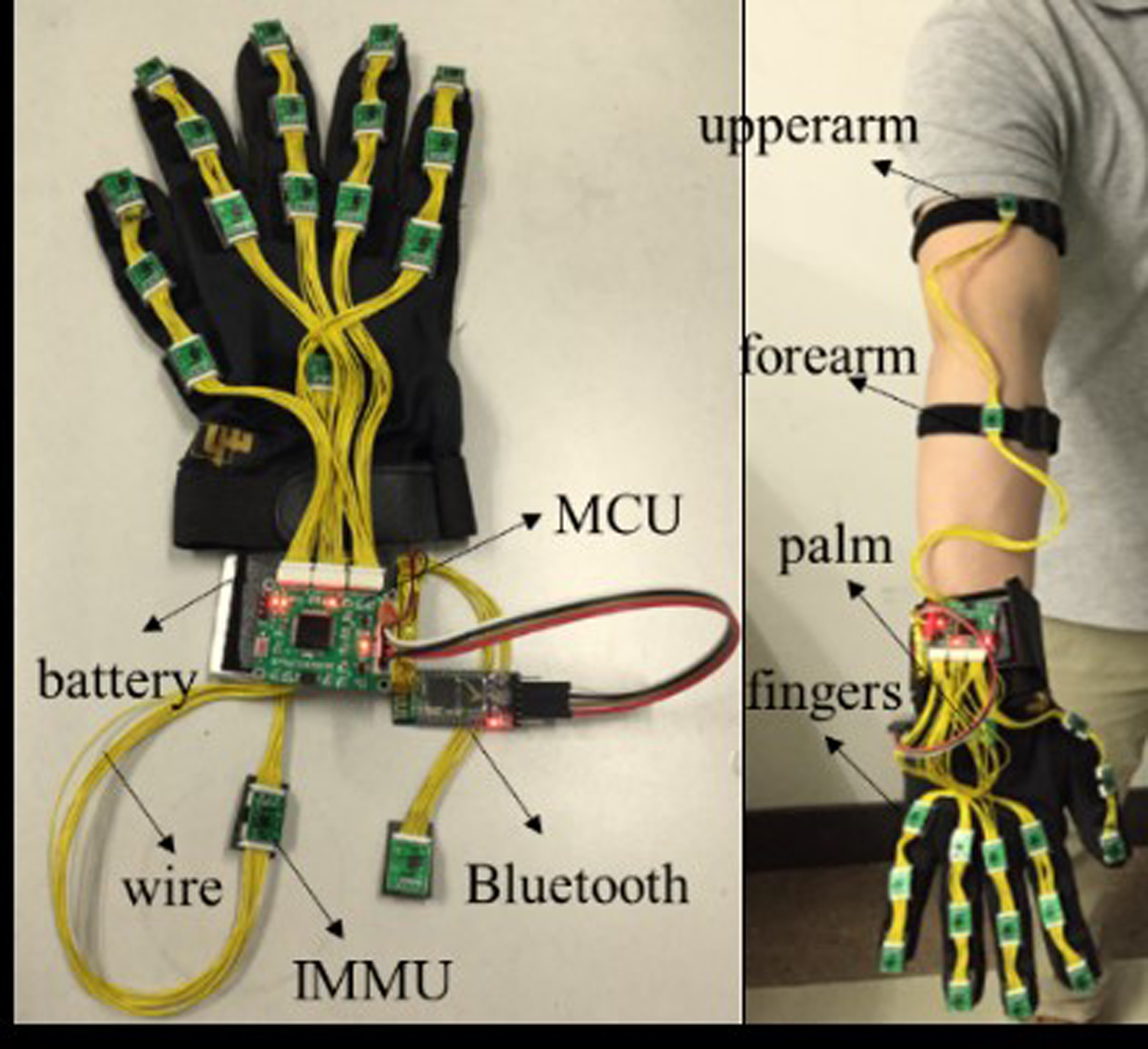
The wearable device.

3-D orientations of the IMMUs.
Orientations of the gestures.
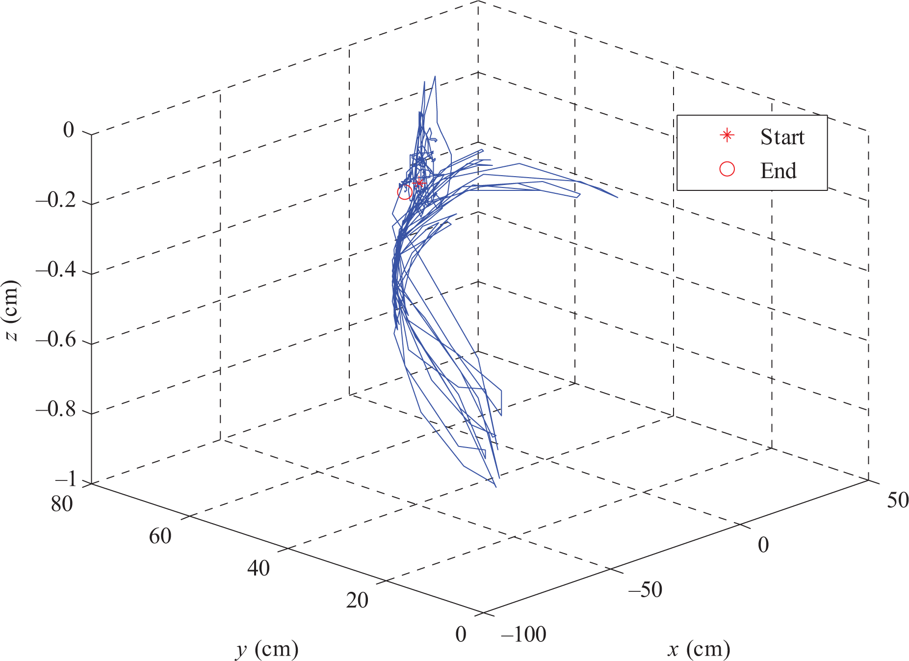
The positions of the palm.
As can be seen in Figure 10, in 0–4 s, the arm and hand keep static. In 4–12 s, only the upper arm is swing up and down. In 18–25 s, only the forearm is swing right and left. In 30–39 s, only the palm is swing up and down. In 43–67 s, only the fingers are bending and opening. As shown in Figure 10, the orientations of the arm, palm, and fingers can be determined in different situations, moreover, the movements can also be easily distinguished. Meanwhile, the accuracy of the results is assessed by the statistics. The root mean square error (RMSE) of the orientations are less than 0.5°, and the RMSE of the positions are less than 5 cm. The detailed results are listed in Tables 3 and 4.
The RMSE of the orientations of the arm–hand.

RMSE: root mean square error.
The RMSE of the positions of the fingertip.

RMSE: root mean square error.
As shown in Figure 12, the author wore the device. The PC received the estimate results by the Bluetooth and shows the interface, which is also displayed on the television. Then, four gestures are captured by the data glove and demonstrated by the virtual model in the television. The first gesture is bending the right fingers, the second gesture is bending the arms, the third gesture is raising the forearms, and the fourth gesture is left thumb up. It is very intuitive to show the performance of arm and hand motion by the wearable device in real time.

The demonstrations of the motion capture by the wearable device. (a) Bending the right fingers, (b) bending the arms, (c) raising the forearms, and (d) left thumb up.
Robotic teleoperation experiments
In order to develop the robotic teleoperation systems, two different levels of communication are used, a standard RS-232 and a network communication to transmit the commands. Therefore, two communication subsystems are involved. The network communication subsystem is based on the client/server network architecture. For simplicity, the server and client components were integrated to the wearable device and the robot’s communication subsystem, respectively. This integration scheme allows to create the master and the slave control stations of the system. Both stations are running on standard PCs. The network communication technique is based on sockets, and the software for the system was written in Microsoft Visual C++. The master control station initializes the server to accept valid connection requests. When a connection is accepted, the wearable device is activated and data packets are periodically read from the device. If a valid command is defined, it is sent to the robotic arm and robotic hand. The slave control station begins with a connection request. If the connection is accepted, the robot is initialized and a session is started. During the session, commands are continuously received from the master control station and divided into the robotic arm’s commands and robotic hand’s commands. Only if the command does not exceed its operation limit, it is separately sent to the robotic arm and robotic hand. The teleoperation system is considered as a real-time system, the influence of time delay can be ignored.
Firstly, the experiments of teleoperation of Barrett robotic hand by the wearable device are implemented. The robotic hand has three fingers, hence the bending of PIP joints of forefinger, mid-finger, and thumb are used to teleoperate the Barrett hand. The four status of teleoperation are shown in the Figure 13. The robotic fingers can bend fluently following the motions of human fingers. Moreover, the experiment of simultaneously teleoperation of 11DOF robots is implemented. Four different states of robotic hand–arm are shown in Figure 14. We can find that the robotic arm has fluent movements following the motion of arm, and the robotic hand and robotic arm can be operated simultaneously.
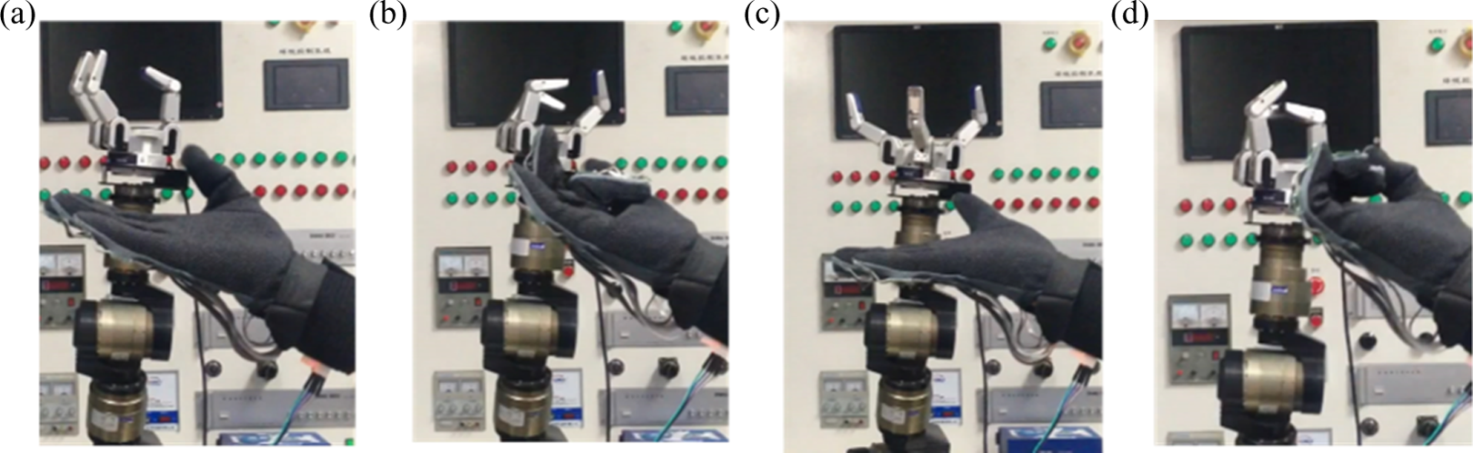
Teleoperating Barrett robotic hand. (a) Bending the thumb, (b) bending the forefinger and mid-finger, (c) opening the forefinger and mid-finger, and (d) bending the three fingers.

Simultaneously teleoperating 11DOF robotic system. (a) Initial position, (b) rotating the wrist, (c) bending the fingers, and (d) opening the fingers. DOF: degrees of freedom.
Then, the experiment of teleoperation of 10DOF robots is implemented. The whole processes of grasping tube and releasing the tube by teleoperating the UR-Barrett robotic hand–arm are shown in Figure 15. First, the operator moves the palm to teleoperate the robotic arm approaching to the tube from the initial position. Then, the attitude of the hand was adjusted to teleoperate the robotic hand to be the right attitude to catch the tube. And the finger was bent to make the robotic hand closed to grasp the bottle. After that the hand was lifted to teleoperate, the robotic arm lifting and the wrist was rotated to adjust the attitude of robotic hand. Then, the robotic arm was left by the hand moving. During this stage, the finger stayed bending to make the robotic hand hold the bottle. The finger was extended to open the robotic hand to release the bottle until the robotic arm arrived the right position. We can find that the robotic arm has fluent movements following the motion of arm, and the robotic hand and robotic arm can be operated simultaneously. Thus, the operator can teleoperate the robotic hand and robotic arm to finish the task by the proposed teleoperation system.

Simultaneously teleoperating 10DOF robotic system. (a) Initial position, (b) moving to the target, (c) adjusting the attitude, (d) closing to the tube, (e) grasping the tube, (f) lifting the tube, (g) leaving the target, (h) returning the target, and (i) releasing the tube. DOF: degrees of freedom.
From these experimental results, it can be concluded that the robotic systems can be teleoperated as imitating the movement of the human arm and hand. Thus, the proposed robotic teleoperation systems are intuitive and robust to finish the related tasks.
Discussion
The proposed wearable multimodal fusion device can capture the more information of gestures than the traditional wearable devices. Hence, the motions of human arm and hand can be fully utilized by the robotic teleoperation systems. Especially the robotic arm–hand systems can realize imitative movement as the motions of human’s arm and hand are simultaneously used in the teleoperation. The proposed systems can avoid complex motion planning, while the robots perform complex tasks. They are more effective and more convenient to fulfill the tasks. In future, the tactile information of robotic hand can be used, 16 –18 which will improve the grasp for teleoperation.
Conclusion
This article presents the design, implementation, and experimental results of robotic teleoperation systems using a wearable multimodal device, which consists of accelerometers, angular rate sensors, and magnetometers. The proposed device covers the whole segments of arm and hand. We deduced the 3-D arm and hand motion estimation algorithms according to the proposed kinematic models of the arm, hand, and fingers, and the attitude of the gesture and positions can be determined. Superior to other data gloves, it cannot only capture the motion of the hand and also the motion of the arm simultaneously. Hence, this makes it more appealing and convenient for the robotic teleoperation. Two different teleoperation schemes are separately presented for the 11DOF robots and 10DOF robots. The experiments have proved that the operator can teleoperate the robots in a natural and intuitive manner easily.
Footnotes
Declaration of conflicting interests
The author(s) declared no potential conflicts of interest with respect to the research, authorship, and/or publication of this article.
Funding
The author(s) disclosed receipt of the following financial support for the research, authorship, and/or publication of this article: This work was supported in part by the National Natural Science Foundation of China under Grants 61503212, 61327809, 61210013, 91420302, 91520201, and U1613212, in part by the National High-Tech Research and Development Plan under Grant 2015AA042306.