
Abstract
Wireless sensor networks are the foundation of cyber physical systems. In loss and delay sensitive wireless sensor networks, there is much room for improving the performance of opportunistic routing scheme. In this article, an adaptive duty cycle control–based opportunistic routing scheme was put forward to improve the performance of the opportunistic routing scheme. Our main work is as follows: (a) the proposed duty cycle control–based opportunistic routing scheme implements the opportunistic routing in the duty cycle–based wireless sensor networks. Compared with the opportunistic routing scheme in the non-duty cycle mode, the duty cycle control–based opportunistic routing scheme can effectively reduce the energy consumption by 55.64%, although the performance in the delay is degraded. (b) Next, adaptive duty cycle control–based opportunistic routing scheme is proposed to reduce the delay of nodes in duty cycle control–based opportunistic routing. In adaptive duty cycle control–based opportunistic routing scheme, the node’s duty cycle is increased in the area where the energy has remaining, so that the network delay can be reduced without reducing the network lifetime. Compared with duty cycle control–based opportunistic routing scheme, the maximum end-to-end delay of the node in the network can be reduced by 69.83%.
Introduction
Cyber physical systems (CPS)1,2 is a complex system that integrates social information based on sensing, embedded computing, network communication, and network control.3–5 As the basis of the whole system, the Internet of Things (IoT) is an important part of CPS.6–8 There are many studies on IoT,3,7,9,10 among which wireless sensor networks (WSNs) are a hot spot.11,12 The performance of WSNs directly affects the performance of CPS.
With the development of micro-processing technology, the processing capacity of sensor nodes is getting stronger, smaller, and cheaper.13–16 Compared with ten years ago, the IPhone’s processors have more computing and storage capacity than personal computers and are more powerful but cheaper, according to research. 17 As a result, various sensor-based devices have seen explosive growth.18–20 Because the sensor network has fast deployment, flexibility, low price, and various sensing devices, it can realize the universal perception of the objective world. Therefore, WSNs are widely used in many fields, such as medical, military, environmental monitoring.21–29
According to research, 30 the loss ratio of wireless communication is several orders of magnitude different from that of wired communication. The loss ratio of wireless transmission is even as high as 20% or more. 31 Therefore, in order to ensure the reliable transmission of WSN data, researchers have conducted a lot of related research.32–34
The first to use is the send–wait (SW) protocol. 35 In such a protocol, each time the sender sends data to the receiver, it waits for the receiver to return an ACK message, which means the receiver has successfully received the packet. If the sender successfully receives the ACK message within the specified time, it indicates that the data transmission was successful. Otherwise, the data transmission is failed, and the same data are sent again in the next clock cycle. The above process ends until the packet is successfully sent or the number of retransmissions reaches the maximum number of retransmissions. Obviously, in this method, a data packet may need to be retransmitted multiple times because of the high packet loss ratio. On one hand, it consumes a lot of energy; on the other hand, it brings a lot of delay to data transmission.34,36,37
In order to improve the deficiencies of the above methods, researchers have proposed various methods. For example, researchers have proposed variants of the SW scheme, such as Goback-N (GBN) protocol, selective repeat (SR).38,39 Kim proposes a send–wait one data multi-ACK (SW-ODMA) automatic repeat-request (ARQ) protocol to improve the reliability of the energy efficiency transmission. 40 In SW-ODMA, every time a receiver receives a packet, the sender returns multiple ACKs. This prevents the ACK from being lost during transmission, resulting in a retransmission.
Opportunity routing (OR) scheme19,41,42 is another routing protocol that takes full advantage of the broadcast function of wireless channels to guarantee transmission reliability. The OR scheme has changed the one-to-one data transmission mode in traditional data transmission. Since wireless communication has broadcast function, when the sender sends packet, all nodes in the range of sender communication can receive data. According to the research, 43 when broadcasting data packets, it is more appropriate to select a node with a receiving rate between 0.1 and 0.9 as a potential receiver. Therefore, when the sender sends data in the OR scheme, multiple nodes receive data at the same time. As long as one receiver receives successfully, the data transfer is successful.
The OR scheme has attracted the attention of researchers,19,42 and some researches on the routing protocol of WSNs based on the OR scheme have been proposed. According to our research, these OR schemes are mainly based on WSNs whose nodes are always awake. 41 Since the sensor node is small and powered by batteries, and its battery capacity is limited due to the cost. Therefore, in order to reduce the energy consumption of nodes, extend lifetime as far as possible, a classic practice is to control the duty cycle of sensor nodes.18,44,45 That is, the sensor node will be awake/sleep periodically. Since the energy consumed by the node in the sleep state is much less than the energy consumed in the awake state, energy saving is achieved. However, WSNs generally adopt asynchronous clock working mode, and asynchronous mode has a disastrous effect on OR scheme. For example, when the sender sends data, there may not be a receiver in the awake state, or there may be few nodes in the awake state. Therefore, at this time, the OR scheme is degraded to a single-sender and single-receiver transmission mode, or the number of receivers is difficult to reach the number required by the OR scheme, making the OR scheme difficult to apply in the duty cycle–based WSNs.
Therefore, this article first proposes a duty cycle control–based opportunistic routing (DCCOR) scheme. Then an improved DCCOR scheme is proposed, namely adaptive duty cycle control–based opportunistic routing (ADCCOR) scheme. The contribution of the main work is as follows:
A DCCOR scheme is proposed in this article, which can make the OR scheme suitable for duty cycle–based WSNs and maintain high performance. The main innovation of DCCOR scheme is that when the sender needs to send data, it calculates the number of nodes in its forwarding set that are awake. If the number of relay sets in the awake state reaches a predetermined number, the data broadcast is started. If the number of nodes in the awake state is less than the predetermined threshold, the sender waits and the wake-up receivers continue to remain awake.
An ADCCOR scheme is proposed which can further improve the performance of the DCCOR scheme. The main improvement of ADCCOR is based on the energy consumption characteristics of the WSN. The node with the remaining energy at the far sink area increases its duty cycle, so that when the sender wants send data, the number of awakened nodes increases, or it takes less time to wait for the remaining candidate nodes to awaken. That is, the delay is reduced. Therefore, ADCCOR scheme dynamically adjusts the sensor node’s duty cycle according to the energy consumption of the node, so that the delay can be reduced without changing the lifetime of the network.
A lot of theoretical analysis and experimental results have confirmed the effectiveness of the proposed scheme. The DCCOR can be applied to duty cycle–based WSNs, and its energy consumption is reduced by 55.64% compared with WSNs without duty cycle. The proposed ADCCOR scheme reduces the delay by 69.83% compare with the DCCOR scheme, without reducing the network lifetime.
The rest of this article is organized as follows: Section “Related work” mainly introduced the research associated with this article. Section “System model and problem statements” mainly introduced the related model used in this article. Section “The design of ADCCOR scheme” gives the DCCOR scheme and ADCCOR scheme of related specifications. In section “Performance analysis and comparison,” we investigated the OR scheme, the DCCOR scheme and the ADCCOR scheme from the angle of energy consumption and delay both analyzed. Section “Conclusion” gives a summary of this article.
Related work
The most important function of WSNs is to sense data and collect data.46–50 Collecting data is mainly through the multi-hop routing of the self-organized network between sensor nodes to route data from the source node to the sink. Routing strategies have been fully studied on WSNs. 41 Therefore, there are many studies related to it. The main factors that are considered in the routing scheme are as follows:
In WSNs, the energy consumption of sensor nodes mainly has the following parts: 56 (a) energy consumed due to transmitting data; (b) energy consumed due to receiving data; (c) energy consumed due to idle waiting; (d) energy consumed due to keeping sleep. According to research, up to 70% of the energy consumed in WSNs is used for data operations, of which data sending and receiving consumes the most energy. 15 There are many studies showing: The energy consumption of the node in idle waiting time is almost equal to the energy consumption of the received data. 15 Therefore, to save the energy of nodes, the nodes should be in a sleep state as much as possible.
Therefore, the researchers proposed the duty cycle based on WSNs.44,45 In such a network, the node will periodically undergo awake/sleep rotation. When the node is awake, it will be able to perform data operation, while there will be no communication during sleep.
Obviously, the routing scheme needs to make the delay of the data reaching the sink as small as possible. In WSNs, there are many factors influencing delay, among which one of the most important factors influencing delay is the reliability of communication channel.41,59 If the wireless channel is reliable, the packet can be received by the receiver with only one transmission. If the channel quality is not high, it takes many times to be received by the receiver. Obviously, in a network with a bad wireless communication link, its delay will be significantly higher than that of a good communication network. In addition, the delay is also related to the routing scheme.
The reliability of data transmission refers to the probability that the packet sent by the source node is successfully received by sink after multi-hop routing. Obviously, the reliability of data transmission is an important performance for WSNs. If the data cannot be collected reliably, it will damage the basic functions of the WSN.
There is a much higher loss ratio in wireless communication than in wired communication.37,40,44 In addition, there may be attacks in WSNs,51,52 where malicious nodes interfere with data transmission and damage the reliability of data transmission. Therefore, security is also a problem worthy of attention.7,53
Research on energy efficiency and lifetime of routing
In order to reduce the energy consumption of nodes and prolong the lifetime of the network, researchers have proposed many routing schemes from different perspectives,54,55 which are summarized as follows:
1. A class of routing strategies based on multi-hop routing.
The first one proposed is the shortest routing scheme. This is the most used routing scheme for WSNs, and the network requirements are relatively simple, which is very suitable for this kind of self-organizing WSN. The main idea of the shortest routing scheme is by continuously iterating, find a path for the node to let its data packet reach to the sink with minimum number of hops.
The standard of the shortest routing scheme to select next hop is the number of hops of nodes from sink. In fact, the standard for selecting next hop in a sensor network with GPS can be the distance of the node from the sink. 62
There is no energy consideration in the shortest routing scheme. Therefore, subsequent researchers proposed an energy-balanced routing scheme. 17 The main idea of the routing scheme for energy balance is as follows: The set of nodes in the sender’s range that are closer to the sink than the sender is called the sender’s forwarding set. Obviously, in the energy balance routing scheme, the node closest to the sink and with the maximum remaining energy is selected as the relay node in the forwarding set. The energy balance routing scheme is often a multi-objective optimization problem. The solution is to give a certain weight to each of the two target values, then combine the weighted average into one target value, and then select the node with the largest target value as the relay node. 50
2. Clustering routing scheme.
Different from the above routing scheme, this scheme first divides the network into several clusters. Each cluster selects one node as cluster head, while other nodes in the cluster are called cluster members. When data are routed, all member nodes send their own data to the cluster head of the cluster. The cluster head receives data from all nodes in the cluster for data fusion and then passes through multi-hop between Cluster heads or directly sends it to sink. In fact, if you only see the cluster head node as the node to be routed, the two routing strategies above are actually the same.
Research on delay optimization
In addition to energy consumption, there is another issue that people pay attention to in WSN, which is the delay of data transmission.44,57,58 The delay of data transmission can be divided into two categories. The first type is one-hop delay, which refers to the delay caused by packet transmission in a single hop. The second kind of delay is the end-to-end delay of data transmission, which refers to the time required for data packets to be received by the sink node from generation. Delay is an important indicator in WSNs, and it has received wide attention from academia.
In ORW, 19 the researchers defined a variable EDC that represents the time from when a node starts transmitting a packet to when the packet is successfully received by the relay node. The EDC is added for each hop to calculate the time required for the packet to be received by the sink node. Forwarding according to the path with the smallest accumulated time, the resulting delay is minimal.
Liu et al. 56 proposed an FFSC strategy. This is also proposed for networks that use opportunistic routing.
When the sender needs to send data, if there is a node in the forwarding set that is awake and closest to the sink, the sender can get the best relay. At this time, the sender can immediately transmit the data with the farthest distance. However, if the node in the awake state is not the node closest to the sink, then the sender has two options: (a) select the node that is closest to the sink from all nodes that is in the awake state as the relay, and immediately transmit the packet. At this time, the one-hop delay is small, but the number of hops of the route will be more, and the end-to-end delay may be larger. (b) Wait for a while, until the node closest to sink in all forwarding nodes wakes up. At this time, the sender needs to wait for a period to send data, and its one-hop delay is large. However, the sender chooses the node closest to sink as the relay, so the number of route hops is relatively small in this way, and the delay can be reduced.
In order to find the best solution, the authors combine the two problems of minimizing the number of transmission hops and minimizing delays, making them a dual-objective optimization problem and obtaining the final optimized routing.
System model and problem statements
Network model
The network is a circular network with sink node as the center. The nodes in the network are evenly distributed in the network with density
The network is a type of WSNs based on duty cycle. Nodes in the network work periodically using sleep/awake rotation. The length of the cycle is
Reliability model
In this article, the reliability model of the node we refer to the model given by Joo. 59 Since the transmission of data packets between nodes is unreliable, the data packets are lost with a certain probability during the transmission between nodes. During the transmission of the node, the propagation path loss can be expressed as
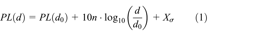
where
Suppose the node’s transmission power is


where
Then, according to the communication link model, the success rate of transmitting data packets between nodes can be expressed as 59

where
Energy consumption model
For the energy consumption model of the node, we can refer to Joo. 55 In the process of transmission, we mainly have the following three types of data packets, which are the data packet containing the information collected by the node, the ACK packet, and CTS packet responsible for the communication between the secondary nodes.65,66
Since the ACK packet and the CTS packet itself are small, and the energy consumed by the node when receiving these packets is much less than the energy of the transmitted packets. When analyzing the ACK packet and the CTS packet, we only calculate the energy consumed to send these packets, regardless of the energy consumed to receive them.
The energy consumed by the node in sending (receiving) data packet is calculated by the following formula

where

where
In order to calculate the total energy consumed by a node in a data transmission, it is necessary to calculate the number of packets transmitted by the node. We use
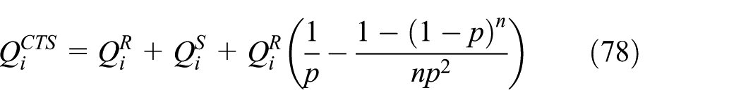
The energy consumed by the current node to send the data packet, the energy consumed by the received data packet, the energy consumed to send the


where

The total energy consumed by a node to transmit a packet is

Problem statement
The objectives of the DCCOR scheme and the ADCCOR scheme optimization proposed in this article are the same, that is, to design the opportunistic routing scheme for the duty cycle WSN. At the same time, the data transmission reliability of the network meets the requirements of the application, the delay of data transmission should be minimized, and the network lifetime should be maximum. Therefore, the optimization objectives of this article can be expressed as follows:
The minimum end-to-end delay, which refers to the time difference between the data packet generated by a node and the successful reception of the data packet by the sink node. We use

The longest network lifetime. In this article, we define the lifetime of the network as the death time of the first node in the network that died due to energy exhaustion. We suppose that the initial energy of the node with a distance of

Suppose that the initial energy of all nodes in the network is the same, in order to make the lifetime of the network as long as possible, the energy consumed by the nodes in each round of data transmission should be as small as possible. The node that consumes the most energy for each round of data transmission directly determines the lifetime of the network.
In summary, we can summarize the optimization goals of this article as

where
The design of ADCCOR scheme
In this chapter, we first introduce the DCCOR scheme. Based on this, the mechanism of automatically adjusting the duty cycle is added, and the ADCCOR scheme is proposed.
DCCOR scheme
The main ideas of the DCCOR scheme are as follows: first, sender selects the forwarding set (FS) based on its transmission power. The specific approach will be mentioned below. After sender determines the FS, it listens to the channel if there is a packet to send. In the DCCOR scheme, each node is required to initiate a hello message when it is switched to the awake state. After the sender, which is listening for channel, receives the hello message, it sends an RTR (Request to Receive) message to the node, such as A, indicating that the sender is ready to broadcast data. At the same time, sender starts counting
After the broadcast, the relay node that received the packet returns an ACK message to the sender. If the sender receives an ACK indicating that the packet was successfully sent, sender returns ETS (End to Send) message. After receiving the ETS message, the data are transmitted. If the node that successfully received the packet is not the sink, the node becomes the new sender and repeats the above process until the packet is sent to the sink.
The above process can be described by Algorithm 1.

In the algorithm, symbol representation and meaning are as follows:
hello: the message that node sends when it wakes up;
RTR: the message that the sender returns to the receiver’s request to receive data;
ACK: A message sent to the sender after the receiver successfully receives the data packet to inform the sender that the receiver has received the packet successfully;
ETS: indicates that the data were sent successfully.
For example, in Figure 1, when node S wants to send a packet, it begins to monitor the state of the nodes in the FS, that is, the states of nodes A, B, C, D, and E. Assume that the initial threshold number of candidate nodes is 3, FS is empty, and the value of the counter is 0.

An example of a network using the DCCOR scheme.
When a node in the FS, such as A, wakes up, it sends a hello message to node S. After receiving the message, the node S knows that a new node wakes up, first increments the value of the counter by 1, and then determines whether the value of the counter is less than the threshold. In this example, the value of the counter is 1 and less than the threshold (3). In this case, node S sends an RTR message to node A to keep it in the awake state, while node S continues to listen to the status of other nodes in the FS. When a node such as B wakes up, the value of the counter becomes 2, and the threshold is still not reached, so node B also remains in the awake state. Until a node in the FS, such as C wakes up, the value of the counter is incremented by 1, reaching the threshold. At this point, node S can broadcast the packet.
If node A, B, or C successfully receives the data packet, it will send an ACK message to node S. Once the node S receives the ACK message, it proves that the transmission was successful. In particular, the method by which node A determines its candidate set
Subsequently, the node broadcasts a
Through the above steps, the forwarding set of the node A can be determined. The above method can be represented by Algorithm 2.

In the algorithm, symbol representation and meaning are as follows:
Theorem 1
After the transmission power of the node is selected, the range of the transmission radius of the node can be calculated by the following formula

Proof
Suppose that the receiving rate of the node whose distance to node S is

Here,
According to equation (2), the path loss of the node is

where
Finally, based on equation (1)

Here,

In this article, we specify that the packet size is
Theorem 2
According to the range of the transmission radius, the success rate of transmission at different transmission radii, and the number of nodes under the corresponding transmission radius, the average weighted transmission radius of the node is

where
Proof
Since the probability of successful packet transmission and the number of receiving nodes under different transmission radius are different, it is necessary to weight these values to average.
We suppose that there is a node
In Figure 2, the distance between the node S and sink is
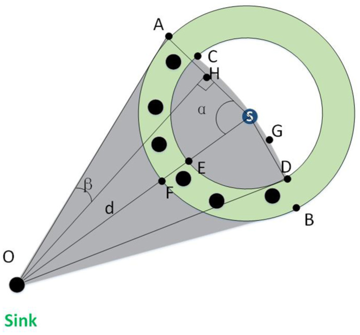
Method for calculating the area of a special area.
According to the trigonometric formula

The acreage of the fan-shaped AOS is

which is
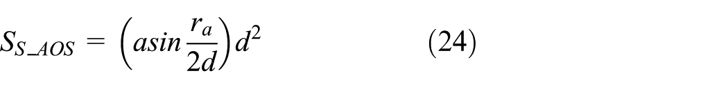
The acreage of △AOS is

Therefore, the acreage of the irregular area ACS is

The fan-shaped ASF center angle is

The acreage of the fan-shaped ASF is

The acreage of the irregular area AFSC is

which is

Similarly, the acreage of the irregular area DESG is

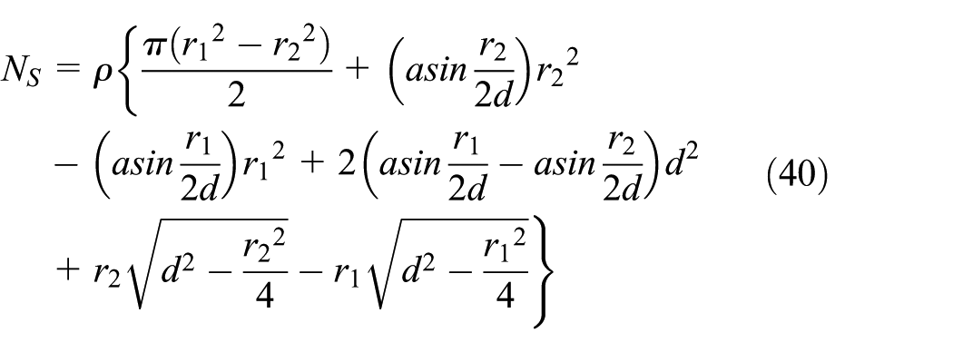
According to equations (30) and (31), we can give the irregular area of the overlap

When

Simplified to

Therefore, the transmission radius

Theorem 3
The size of forwarding set of node S can be expressed as

where


Proof
Assuming

That is
Theorem 4
Assuming that the duty length is

Proof
Obviously, the delay of node S mainly depends on the time when the nth candidate node wakes up.
Let us first consider one of the

where
Since the node must wake up in one of the

Then, at slot
The probability that a node wakes up after slot

When calculating the delay of a single hop of a node, we discuss it in three cases.
Assuming that node

Node
In the first part, there are at least

where

where “!” indicates the factorial.
Assuming that node

Node
In the first part, at most
Suppose that node

Node
In part 1, there are

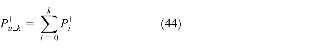
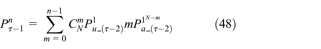
In summary, the delay of node S is
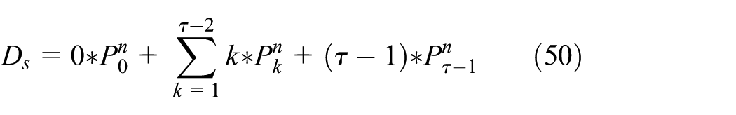
Substituting the above equations (46), (48), and (49) into equation (50)

The energy consumed by the node can be divided into the following two parts. One part is the energy consumption generated by the node when transmitting data, the other part is the energy consumed when the node keeps listening. We first calculate the energy consumption in the first part.
We have made the following division of the network with radius
We call the ring closest to sink the ring 0, from inside to outside, in order, ring 0, 1, 2, and
The inner radius of ring
Theorem 5
According to the above method for dividing the network, the number of nodes on each ring is


where
Proof
Since the nodes in the WSN are evenly distributed, as long as the area of each ring is known, the number of nodes on the ring can be easily obtained. The area of ring

Simplify the above formula

In particular, for the ring 0

The density of nodes in the network is


It should be noted that the calculated value is a decimal, and in reality, the number of nodes must be an integer. Therefore, the calculated value needs to be rounded to approximate.
Consider the packet transmission situation of a certain node separately. When the node is in the edge area of the network, it only sends the data packets collected by itself and does not need to be the relay of other nodes. We suppose that in each round of transmission, each node generates only one data packet. Then, the number of data packets sent by these nodes in the edge area of the network is 1, and the number of received data packets is 0. Correspondingly, the number of ACK packets sent by the node is 0, and the number of sent CTS packets is 1. For nodes in other areas of the network, they need to send their own data packets on one hand and forward the data packets sent by the previous hop node on the other hand.
Theorem 6
Suppose that in a network with radius


Proof
For the node on ring

Simplify the above formula

The data packet sent by the node on ring

Simplify the above formula
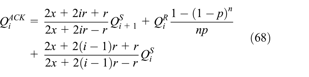
The ACK packet sent by the node on ring
The nodes on ring

Substitute relevant formulas and simplify
The CTS packet sent by the node on ring
The number of CTS packets sent by the nodes in the third part is related to their priority in the candidate set. Since all sensor nodes are already defined in the WSNs, except for the location and the distance from sink, all other performance and status are the same. Therefore, during a round of data transmission, the probability that a node is at a certain priority is
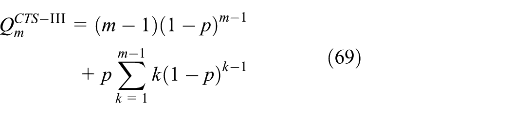
Let us suppose

Multiply both sides by

Subtract equation (71) from equation (70) to
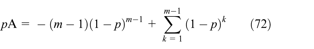
Substituting the above formula into equation (69) is
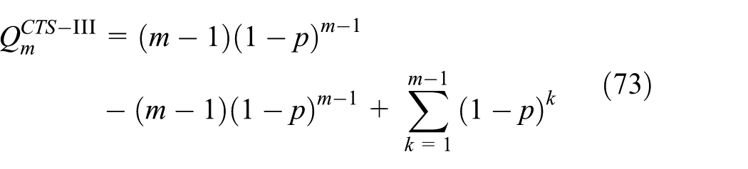
Simplify the above formula

Summation formula by equal ratio series

Since the nodes may be at different priorities in different transmission rounds, we average the number of CTS packets at different priorities

Simplify the above formula

In summary, the number of CTS packets sent by the nodes on ring
Substitute relevant formulas and simplify

Combined with the analysis in the energy consumption model in section “Energy consumption model,” we get the energy consumption when the node transmits the data packets. Next, we consider the energy consumption when the node keeps listening.
Theorem 7
Suppose that the size of forwarding set is

Proof
We suppose that the node
According to equation (42), the probability that a single node wakes up at a certain time in the entire duty length is

where
When

The probability that a single node will wake up in or before slot

Since all nodes in the network will keep awake for a slot, the average time for these

Since node

When
The power of the node to maintain low power listening is

ADCCOR scheme
Combined with the analysis in the energy consumption model in section “Energy consumption model,” we get the energy consumption when the node transmits the data packets. Next, we consider the energy consumption when the node keeps listening.
By combining duty cycle control with opportunistic routing, the DCCOR scheme combines the advantages of low power consumption and high reception rate. Due to the characteristics of the wireless network itself, the number of data packets transmitted by the nodes at the edge of the network is much smaller than that of the nodes near the sink, so that the energy consumed by the nodes in the far sink area is much smaller than that of the nodes near the sink area. Thus, when the energy of the node near the sink area is exhausted, the far sink area node still has a large amount of energy remaining. Because the node in the near sink area dies, there is no node in the network that can directly communicate with the sink, that is, the network has also died. Thus, there is a case where a large amount of energy remains in the far sink region node when the network dies.
In order to make full use of this part of the energy, we propose the ADCCOR scheme. That is, based on the DCCOR scheme, the residual energy is used to increase the time that the node keeps listening, to reduce the delay. Except for the first round of data transmission process, which is the same as the DCCOR scheme, in other rounds, it is necessary to adjust the duty cycle continuously.
Theorem 8
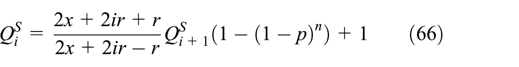
We use

where


Proof
When we calculate the duty length of round


where
After m rounds, the nodes on ring 0 consume

We assume that the length of the entire clock cycle is

In summary, the ADCCOR scheme can be summarized by Algorithm 3.

The meaning of the symbolic representation in the algorithm is as follows:
Performance analysis and comparison
In section “The design of ADCCOR scheme,” we have a detailed description and analysis of DCCOR and found that after the duty cycle control is added to the OR, the delay of the node becomes significantly larger. Therefore, we can reduce the delay of the node by changing the duty cycle of the node without changing the lifetime of the network. In the DCCOR scheme, by combining the duty cycle control and the OR, it has the characteristics of low power consumption and high receiving rate. Due to the characteristics of the WSN itself, the nodes in the far sink area consume far less energy than the nodes in the near sink area. When the nodes in the near sink area die due to energy exhaustion, the nodes in the far sink area have a large amount of energy remaining. Since there are no more nodes in the network that can communicate directly with the sink node, the entire network is in a paralyzed state. Even if there are more energy left in the nodes in the far sink area, it will not help. Therefore, we propose the ADCCOR scheme, which is based on the DCCOR scheme to adjust the duty cycle of the nodes with the remaining energy, to use these energy to reduce the delay.
Below, we will analyze the DCCOR scheme and ADCCOR scheme from the perspective of energy consumption and delay to prove our point of view.
About energy consumption
In section “DCCOR scheme,” we give a detailed method for calculating the energy consumption of nodes in a network using DCCOR scheme and ADCCOR scheme, which will not be repeated here. When calculating the node energy consumption in a network using OR scheme, we can make up the following two parts.
The energy consumed by the node due to the listening. We suppose that the power is

The energy consumed by the node due to the transmission of the packet. Compared with DCCOR scheme and ADCCOR scheme, the number of packets sent and received by nodes in OR scheme are the same, and the number of CTS packets is the same too. Different from DCCOR scheme and ADCCOR scheme, the node in OR scheme does not need to send ACK packets to the upper hop and the next hop, and only needs to send ACK packets to the node whose priority is lower than it. Therefore, the number of packets sent (received) by the node in OR can be expressed as


The definition of the above variables is the same as in section “DCCOR scheme.” Then, according to equations (7)–(10), the energy consumed by the node to send data packets, receive data packets, send ACK packets and CTS packets during a round of data transmission can be obtained; adding those energy together is the total energy consumed due to the transmission of the packet. By adding up the energy of the above two parts, we can get the total energy consumed in the OR scheme.
We suppose that there is a network with a network radius of

Energy consumption due to transfer packets in three different OR schemes.
Since the nodes in the DCCOR scheme and the ADCCOR scheme transmit more ACK packets relative to the nodes in the OR scheme, the energy consumed is slightly higher than the OR scheme.
In the ADCCOR scheme, the duty cycle of the nodes in different rounds may be different, and the energy consumed to keep listening is different too. In Figure 7, we give the energy consumed by the nodes in the first five rounds.

Energy consumption due to listening in ADCCOR scheme.
In order to facilitate comparison with the OR scheme and the DCCOR scheme, we use the average of the energy consumed by listening in the previous rounds. Since the energy consumed by the nodes in the OR scheme and DCCOR scheme to keep listening in different rounds is the same, it is only expressed once, as shown in Figure 8.

Average energy consumption due to listening in three different OR schemes.
In terms of the energy consumed by listening, the nodes in the OR scheme consume the most because they are always in the awake state. The duty cycle of the node in the DCCOR scheme is always at the initial value, so it is the smallest. The duty cycle in the ADCCOR scheme is always greater than or equal to the DCCOR scheme and is not always equal to 1 as in the OR scheme, so the amount of energy consumed is between the OR scheme and the DCCOR scheme.
By summing the energy consumed by the node’s transmitted data packet with the energy consumed by the listening, the total energy consumed by the node can be obtained. Considering that the total energy consumed by the nodes in the ADCCOR scheme may be different in each round of data transmission, we also use the average value, as shown in Figure 9.

Average energy consumption in three different OR schemes.
From Figure 9, we can draw the following conclusions. First, by increasing the duty cycle control, the energy consumed by the nodes in the DCCOR scheme is greatly reduced compared to the OR scheme. The lifetime of the node closest to the sink determines the lifetime of the network. From this perspective, the energy consumed by the node in the DCCOR scheme is reduced by 55.64%. With the same initial energy, the lifetime of the nodes in the DCCOR scheme is extended by 125.43%.
Second, by adjusting the duty cycle of the node, that is, using the ADCCOR scheme, the energy consumed by other nodes increases with the number of transmission rounds except for the node closest to the sink and is always no larger than the node closest to the sink. This means that dynamically adjusting the duty cycle does not affect the life of the network. Below, we will prove that by adjusting the duty cycle, the purpose of reducing the delay is indeed achieved.
About delay
Obviously, by increasing the duty cycle control, the node is periodically in a sleep state, and the purpose of reducing energy consumption is achieved. Since the relay node may be in a sleep state, data transmission is interrupted, resulting in a delay. To reduce the delay, we used a method of dynamically adjusting the duty cycle.
In Figure 10, we give the one-hop delay of the node in the DCCOR scheme and the ADCCOR scheme. Since the duty cycle varies in different rounds in the ADCCOR scheme, the size of a time slot is different too. Therefore, we measure the delay in seconds (s).

Average one-hop delay in DCCOR scheme and ADCCOR scheme.
As can be seen from Figure 10, after increasing the method of adjusting the duty cycle, the one-hop delay of the node becomes smaller and smaller with the increase of the transmission round. In particular, since the sink node is always in the awake state, the delay of the node that can directly communicate with the sink is zero. As of the 25th round, the one-hop delay in the ADCCOR scheme is reduced from 44.52% to 75.50% relative to the nodes in the DCCOR scheme.
The above one-hop delay only reflects the impact of the ADCCOR scheme on the delay of a single node. In order to reflect its impact on the delay of the entire network, the end-to-end delay needs to be analyzed. In Figure 11, we give the end-to-end delay of the nodes in the DCCOR scheme and the ADCCOR scheme.

Average end-to-end delay in DCCOR scheme and ADCCOR scheme.
Obviously, the end-to-end delay of the nodes in the ADCCOR scheme is significantly smaller than the nodes in the DCCOR scheme, and the farther away from the sink, the smaller the delay. And the more rounds of transmission, the smaller the delay. For the node farthest from the sink node, the maximum end-to-end delay in the network is reduced by 69.83% after 25 rounds. That is to say, after using the ADCCOR scheme, the time that the sink node collects all the packets in the network is shortened by about two-thirds.
Conclusion
As an important part of CPS, WSNs are the cornerstone of the whole system. The performance of WSNs greatly affects the performance of CPS. To this end, our goal is to find better routing solutions, optimize the performance of WSNs, and contribute to the development of CPS.
Related scholars have proposed an OR scheme to improve the reception rate of nodes in WSNs and achieve the goal. However, the OR scheme only focuses on the receiving rate of the node, completely ignoring the energy consumption of the node. In WSNs, in order to reduce the energy consumption of nodes, our most common method is to add duty cycle control. Therefore, in this article, we propose an opportunistic routing that can be applied to the duty cycle–based WSNs, namely DCCOR scheme. According to our research, this article is the first time to apply the opportunistic routing method to the duty cycle WSNs.
Subsequently, in order to make full use of the surplus in the network, we improved the DCCOR scheme and proposed the ADCCOR scheme. The main idea of the ADCCOR scheme is to use the residual energy of the nodes to increase the duty cycle, so that the ADCCOR scheme has a lower delay than DCCOR scheme. The central idea of the ADCCOR scheme is to appropriately increase the duty length of the node (except for the nodes on ring 0) to reduce the delay. Through analysis and calculation, we find that the ADCCOR scheme achieves the goal of reducing node delay without changing the lifetime of the network. This improvement has greatly improved the performance of DCCOR scheme and in the latter comparison with OR scheme, the performance has also been greatly improved.
In summary, we have successfully proposed a DCCOR scheme for use in the duty cycle–based network and improved it. This greatly reduces the energy consumption of the node, and the lifetime of the network is greatly increased, which has a good meaning. Although the delay of DCCOR scheme and ADCCOR in the duty cycle network is larger than that in the non-duty cycle network, this is not the delay caused by the strategy itself, but the problem that all the duty cycle–based networks must exist.
Footnotes
Handling Editor: Zhiyuan Tan
Declaration of conflicting interests
The author(s) declared no potential conflicts of interest with respect to the research, authorship, and/or publication of this article.
Funding
The author(s) disclosed receipt of the following financial support for the research, authorship, and/or publication of this article: This work was supported in part by the National Natural Science Foundation of China (61772554, 61572526, 61572528).