
Abstract
With the rapid growth of indoor positioning requirements without equipment and the convenience of channel state information acquisition, the research on indoor fingerprint positioning based on channel state information is increasingly valued. In this article, a multi-level fingerprinting approach is proposed, which is composed of two-level methods: the first layer is achieved by deep learning and the second layer is implemented by the optimal subcarriers filtering method. This method using channel state information is termed multi-level fingerprinting with deep learning. Deep neural networks are applied in the deep learning of the first layer of multi-level fingerprinting with deep learning, which includes two phases: an offline training phase and an online localization phase. In the offline training phase, deep neural networks are used to train the optimal weights. In the online localization phase, the top five closest positions to the location position are obtained through forward propagation. The second layer optimizes the results of the first layer through the optimal subcarriers filtering method. Under the accuracy of 0.6 m, the positioning accuracy of two common environments has reached, respectively, 96% and 93.9%. The evaluation results show that the positioning accuracy of this method is better than the method based on received signal strength, and it is better than the support vector machine method, which is also slightly improved compared with the deep learning method.
Introduction
With the increasing demand for indoor positioning, it has become an increasingly important issue. The global positioning system (GPS) has been very mature and accurate in outdoor environment. But in indoor environment, because of the obstruction of buildings to satellite signals, GPS cannot work effectively. Therefore, the indoor positioning technology has been widely studied. With WiFi covering almost all indoor sites in people’s lives, such as offices, schools, shopping malls, and families, indoor localization technology based on WiFi is more convenient than the localization technology needed to carry devices. The research shows that the received signal strength (RSS) in WiFi decreases exponentially with the increase in the propagation distance. Then, the location of human is easy to locate by trilateration positioning method. Many existing indoor positioning systems use RSS as the fingerprint, because measurement devices of RSS are relatively inexpensive and easy to obtain. Many wireless devices integrate the modules that can measure RSS, which makes RSS-based positioning methods more adaptive than others. 1 Radio detection and ranging (RADAR), the earliest positioning system-based WiFi, was implemented using RSS as a fingerprint. The system uses a fingerprint positioning method based on machine learning, and it is mainly used in the K-nearest neighbor (KNN) algorithm. First, the KNNs are searched in the fingerprint database to find the K-closest samples to the target fingerprint. The coordinates of these K samples are averaged as the coordinates of the target.
However, there are still some problems about the positioning method based on RSS. One is the multi-path problem, and it will result the reduction of the fingerprint information which is obtained in different time of the same place. The other is that only using RSS is single and rough for indoor localization, which cannot accurately describe the signal characteristics and will cause large errors of localization. 2 In recent years, some devices (such as Intel 5300 wireless network cards) support access to channel state information (CSI) of the physical layer. CSI, as the physical radio frequency of channel property of subcarriers transformed by orthogonal frequency-division multiplexing (OFDM), is a fine-granular and more sensitive indicator of signal characteristics than RSS. In the same environment, compared with RSS, the characteristics of overall structure of CSI are relatively stable. Compared with the single fingerprint characteristics of RSS, CSI-based indoor location technology has more fingerprint features to choose from, such as frequency attenuation characteristics, phase, and energy intensity. 3 At the same time, CSI can be extracted and analyzed through commercial WiFi devices in the widely used 820.11n standard band, including amplitude and phase information. 4 FILA tries to use CSI to reduce the error of the traditional signal propagation model in indoor applications, and it proposes a new ranging model based on CSI, which determines the final location of the target through the trilateral positioning. However, the measurement model used by FILA is sensitive to the change of environment, which needs to train in specific indoor positioning scenarios so it can obtain suitable parameters to accurately measure; in addition to this, FILA not only requires three access point (AP) devices for the trilateral positioning but also has a requirement for the number of devices. It cannot satisfy the real-time WiFi scenarios, because the target with three AP distance cannot be measured in parallel. The indoor positioning technology–based distance model in most cases need the signal to have line-of-sight transmission paths. However, the indoor environments often have obstacles, causing there being no line-of-sight transmission paths between the transmitter and the receiver, and there is the problem of multi-path effect, which both greatly reduce the feasibility of indoor positioning method based on distance model. However, the indoor location method based on fingerprint information does not need line-of-sight transmission paths and does not require additional hardware and deployment. 5 So, it has gradually become the mainstream technology of indoor location based on WiFi.
In this article, we propose a multi-level fingerprinting approach, which is composed of two-level methods: the first layer is achieved by deep learning and the second layer is implemented by the optimal subcarriers filtering method. This process includes raw CSI data collection, feature extraction, deep learning training fingerprint library, and uses second-level optimal subcarrier filtering method to optimize and enhance results. This method based on CSI is termed multi-level fingerprinting with deep learning (MFD). Deep neural networks (DNNs) are applied in this deep learning of the first layer of MFD, which includes two phases: an offline training phase and an online localization phase. In the offline training phase, DNN first initializes the weights randomly. Then, the predicted values are obtained by forward propagation and the difference between the predicted values and the true values is measured using mean square error (MSE). Finally, backpropagation learning is used to minimize the MSE to find the optimal weights. In the online location phase, the first five closest positions are obtained through the accuracy rate of the predicted value obtained by the forward propagation. According to the probability of the first five closest positions, they are output from the largest to the smallest sequence, and the corresponding classification probability information is output at the same time for second levels to use. The optimal subcarrier filtering method of the second layer selects the first three subcarriers as the optimal subcarriers by extracting the characteristics of the subcarriers, then optimizes the first layer results based on the CSI of the optimal subcarriers, and obtains the final results. The evaluation results show that the positioning accuracy of this method is better than that of the method based on RSS, and it is better than the support vector machine (SVM) method, which is also slightly improved compared with the deep learning method.
The rest of this article is organized as follows. Some preliminaries are introduced in section “Preliminaries.” This is followed by the MFD system in section “MFD system.” And, evaluation is presented in section “Evaluation.” In section “Related work,” related work is reviewed and conclusion is presented in section “Conclusion.”
Preliminaries
In wireless communication systems, a wide range of bandwidth is usually divided into multiple channels to transmit signals. However, a single channel just transmits a single signal, which often leads to waste. In order to make more full use of the channel bandwidth, the channel can be further divided into subchannels, and OFDM is a widely used frequency-division multiplexing technology. 6 OFDM greatly improves the channel transmission efficiency, and because the subcarriers are orthogonal to each other, it has strong inter-channel interference immunity. In addition, CSI can also distinguish signals from multiple paths, and the influence of multi-path effects is small, so CSI is more stable than received signal strength indication (RSSI).
Figure 1 shows RSS values for different locations at the same time. In a square area of 7 × 7, each square with a length of 0.6 m represents a sampling point. At the same time, the same color is marked in different positions in which the RSS values are same. As shown in Figure 1, there are 16 squares with green color, and the RSS value is 36, and the color is yellow with 10, and the RSS value is 37, accounting for 33% and 20% of the total sampling points, respectively. It is precisely because of the single characteristic of RSS that the discrimination of each location is not very obvious. However, as shown in Figures 2–5, the CSI distributions of the position point 1, the position point 11, the position point 21, and the position point 31 are, respectively, represented. Unlike RSS, CSI is multi-dimensional. As can be seen from the above figures, each packet contains 30 sets of CSI amplitude information representing the amplitude of 30 subcarriers. The deeper the blue, the lower the amplitude value, and the deeper the yellow, the higher the amplitude value. Each position point can be distinguished by 30 sets of amplitude values. Due to the high dimensionality of CSI, the CSI information features are highly differentiated, and the fingerprint characteristics of each location can be reflected in a finer granularity. So, we use more granular CSI information to extract features.

RSS value distribution diagram.
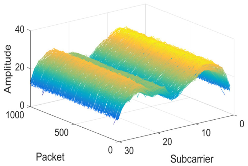
Three-dimensional distribution of CSI amplitude at position point 1.

Three-dimensional distribution of CSI amplitude at position point 11.

Three-dimensional distribution of CSI amplitude at position point 21.

Three-dimensional distribution of CSI amplitude at position point 31.
The Intel 5300 network card used in this article has three receiving antennas, and 90 CSI data of OFDM subcarriers can be obtained. In order to achieve balance between positioning accuracy and real-time performance, we use the CSI data of 30 subcarriers of one antenna. Then, the channel matrix H can be expressed as

Each of the subcarriers

The CSI amplitude information of some adjacent location will also be very close. Therefore, after using the deep learning of the first layer to train each position weight as the fingerprint, we have used the optimal subcarrier filtering method of second layer to distinguish the points of the CSI amplitude information closer.
MFD system
This chapter introduces the MFD system mainly in three aspects. The first section will introduce the overall process of the MFD system from receiving the CSI data to locating the location of target; and, the second section will mainly introduce the deep learning of the first layer and explain how to train weights for each position to establish the fingerprint library after receiving the CSI data; then, the last section mainly introduces the optimal subcarrier filtering method of second layer, which is about how to filter the optimal subcarrier and how to use the optimal subcarrier.
System architecture
The system architecture diagram of MFD system is shown as Figure 6. The system sends signals through a wireless router, and a receiver with three antennas receives signals. Each antenna at the receiver side can receive CSI data of 30 subcarriers. Each packet contains 90 CSI raw data. The data package containing 90 CSI raw data can be read directly by a microcomputer equipped with Intel 5300 network card, which is written the program in advance. After obtaining the CSI data of 30 subcarriers, we only need amplitude information of CSI to train fingerprints. In the training stage under the first layer, the weight information of each position is trained by deep learning as the fingerprint feature to be stored in the database. In the online test phase, the test data set is imported into the MFD test module. The MFD test module is divided into two steps. The first step is to import the test data into the trained DNN to obtain the first layer test result, and the output result includes the first five positions closest to the target position and the corresponding classification probability information. In the second step, the optimal subcarrier test algorithm of the second layer automatically reads the training result obtained in the first step and calculates the probability of each position. Then, the obtained two sets of probabilities of the first layer and the second layer are fused to obtain a final positioning position.

System architecture diagram.
Deep learning
The method that the deep learning on this layer uses is DNN. 7 It adopts a three-decker, that is, input layer, hidden layer, and output layer. In the offline training stage, the input layer inputs CSI amplitude information. DNN first randomly initializes the weights of each position, and the predictive values are obtained by forward propagation. Then, it uses the MSE to measure the difference between the predicted values and the real values, and minimizes the MSE by backpropagation learning the weights of each location information to obtain the optimal weight. Specific steps are as follows:
Read the CSI amplitude data and divide the data into x and y, where x is the training data and y is the corresponding label.
Randomly generate a test set. Divide the original data x and y into a training set and a test set in a ratio of 8:2.
Import data into the neural network for training.
The neural network uses a sequential model in the TensorFlow-based Keras library, which contains input and output layers and three hidden layers. The structure is shown as Figure 7. The first layer is the input layer. The second layer, third layer, and fourth layer are hidden layers which are the fully connected layer, and the number of neurons is 32. The activation function of the second layer and third layer is relu. The activation function of fourth layer is softmax. The last layer is the output layer. We use the dropout method between the second and third layers and between the third and fourth layers to prevent neural network overfitting.
Random initialization such as weights, training iterations 50 times to get neural network model.

Neural network structure.
In the online positioning stage, the first five closest positions to the target location are obtained by the accuracy of the predictive values which are obtained by the forward propagation, and then, the corresponding classification probability information is output for the second layer.
Optimal subcarrier filtering method
The optimal subcarrier filtering method has three steps. The first step is to filter subcarriers. The first three subcarriers that are most sensitive to location changes are selected from 30 subcarriers. In total, 1500 packets are collected at each sampling point. The amplitude in Figure 6 is the average value of the 500 data packets in the middle of the 1500 packets representing the amplitude of the subcarrier at that point. The more obvious the change of the amplitude values between different points in the front and back, indicates that the subcarrier is more sensitive to the change of location information. We use the matrix A of m × n to express the amplitude information of 30 subcarriers at 49 sampling points, in which
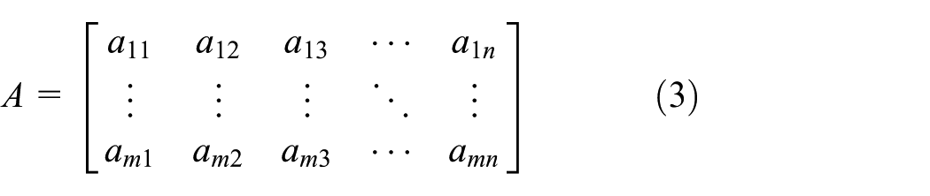

Matrix B is a matrix that is the same size as A. Each element


The second step is to calculate the Euclidean distance. This step calculates the Euclidean distance between the five positions of the first layer and the three subcarriers. The deep learning method of first layer gives five positions in the order of probability, then the Euclidean distance between these positions and the first three optimal subcarriers obtained in the first step is calculated. According to the Euclidean distance, the third step, the probability is calculated. We first normalize the five Euclidean distances obtained in the second step and then seek the proportion of the five positions. After that, we use 1 minus those five proportion to get five new probabilities, which is the probability of second layer.
Evaluation
In this section, we will first introduce the implementation of this experiment in detail and continue to introduce the influence of different system parameters on the experiment. Then, we introduce the experimental results with the comparison of RSS, SVM, and deep learning.
Implementation of experiment
Our experimental platform mainly consists of transmitter and receiver. The transmitter equipped with a TP-Link wireless router is able to use 802.11 transmission standard. There is one antenna and its working frequency is 2.4 GHz. The receiver uses a laptop to collect CSI and installs Intel 5300 wireless network cards. The Intel 5300 wireless network card provides a total of three antenna ports, and can support three antennas to receive data at the same time. Because the wireless router has a transmission antenna and the receiver has three receiving antennas, three link signals can be obtained in theory. And, each link signal has 30 subcarriers, so each packet can contain up to 90 dimensions of CSI data. In order to collect and analyze CSI data conveniently, we install the Ubuntu 10.04 LTS system on the receiver’s computer, using the CSI acquisition software of Tsinghua University, which includes the receiving signal intensity of three signal RSSI and the CSI link information of 90 subcarriers, which is stored in the form of complex numbers, including the amplitude and phase information. What we use is the amplitude information of CSI. We set the contract rate to 200 packets per second.
We experimented in two different indoor environments. One is the relatively empty corridor environment, the other is the conference room environment. As shown in Figure 8, the corridor environment is a 4.2 m × 4.2 m square and the area is divided into 7 × 7 square grid. As shown in Figure 9, the edge length of each grid is 0.6 m, and each grid center is a sampling point with 49 sampling points. The environment of the conference room is shown in Figure 10, with a total of 29 sampling points, as shown in Figure 11. In both environments, the wireless router and the receiving antennas are, respectively, at the end of the area and at the same height with 0.8 m. The size of the interval between sampling points will have a certain impact on the location result whether it is in the offline fingerprint training stage and online positioning stage. Because one of the key points of feature matching is how to distinguish every point without overlapping or blurring. If the interval between the sampling points is too small, it will lead to the characteristics of the point and point too similar. And, it takes a lot of time to collect and calculate the fingerprint library. If the interval between points is too large, the precision of the positioning stage will be reduced. After checking some of the documents and doing some comparative experiments, we find that the location effect is acceptable when the interval between sampling is above 0.3 m. Therefore, we set the interval to 0.6 m. In the CSI collection stage, we set the packet rate to 200 packets per second. Each sampling point is collected about 8–10 s, and at least 1500 packets are collected at each sampling point. The processing of a large number of packets will increase the processing time for the establishment of a fingerprint library under the line, but it can improve the distinguishing feature of each point and improve the positioning accuracy of online positioning.

Corridor for training/test position.

Layout of the corridor for training/test position.

Conference room for training/test position.
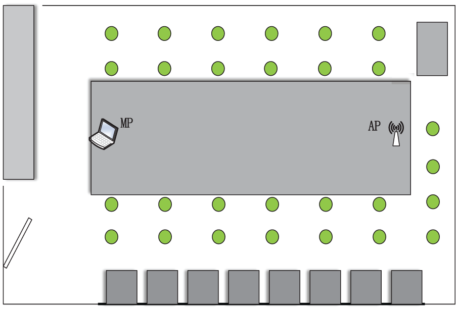
Layout of the conference room for training/test position.
We randomly extract 80% of 1500 data packets for training, when we use deep learning method to train the weights of each sampling point. In order to reduce the amount of operation and reduce the online location time, we use the average of 500 packets in the middle of 1500 packets to perform the operation when using the second layer optimal subcarrier filtering method. We carried out the experiment after 9 p.m. so that the influence of other factors such as walking can be avoided. During the data acquisition, the receiver and the transmitter are at the same height. Each sampling point is sampled in the center of the grid, and the orientation and the positions of the body parts remain the same. Each position is held for 8–10 s, and CSI data of each location can be obtained.
The influence of different parameters
The effects of the number of optimal subcarriers
In the second layer optimal subcarrier filtering method, we first select the first three subcarriers, which are most sensitive to the position change, based on the sensitivity of each subcarrier to the location change. The choice of the optimal subcarrier number is not random, but after we have done a lot of comparative experiments. In the case of the same processing, we take the number of optimal subcarriers from 2 to 30, and the corresponding Euclidean distance is also adapted to the change of the number of subcarrier bands. We carried out the experiment in the above case, as shown in Figure 12, and the positioning accuracy gradually decreases with the increase in the optimal subcarrier number. However, it rises from two to three, and the peak appears at three subcarriers. Therefore, we choose to use three optimal subcarriers at the selection of the optimal subcarrier of the second layer.

The influence of the number of optimal subcarriers on positioning accuracy.
The influence of the height of the antenna
In order to study the effect of antenna height on the performance of MFD, we set up five different experiments to collect CSI data. In the five experiments, we keep the other parameters unchanged, and the height of the antenna is 0.2, 0.4, 0.6, 0.8, and 1.0 m, respectively. Figure 13 shows the accuracy of MFD in the two environments, where the positioning accuracy is 0.6 m at these five heights. From Figure 13, we can see that the change of antenna height does not have a significant effect on the positioning accuracy. With the change of antenna height, the positioning accuracy of conference room environment MFD is fluctuating at 94%, and the positioning accuracy of MFD in corridor environment is fluctuating at 96%.
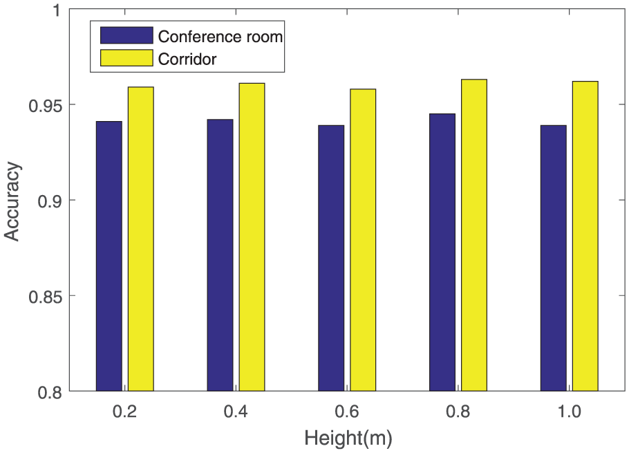
The influence of antenna height on positioning accuracy.
The impact of the packet rate
In order to evaluate the impact of packet rate on MFD performance, we consider MFD at different packet rates. Under the condition that other parameters remain unchanged, we test the performance of MFD under five different packet rates. As shown in Figure 14, in the range of 40–200 packets/s, the performance of MFD in two environments is basically stable.

The influence of packet rate on positioning accuracy.
Positioning results
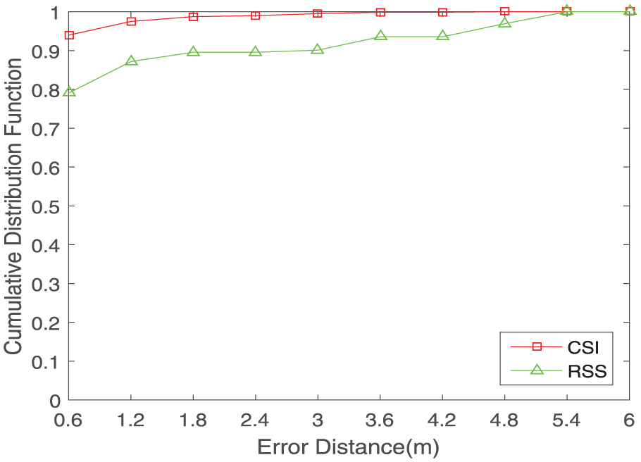
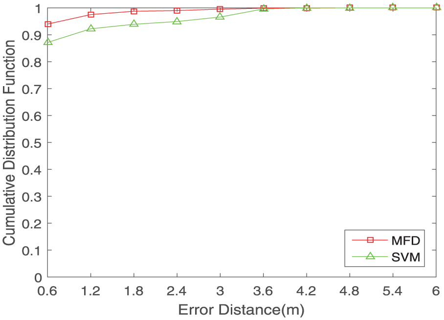
Under the accuracy of 0.6 m, the positioning accuracy of the two environments has reached, respectively, 96% and 93.9%. We also compared the results of RSS positioning in the same environment, as shown in Figures 15 and 16, the cumulative error function distribution diagram of CSI, and RSS under the corridor environment and the conference room environment. It shows that the accuracy using CSI is obviously higher than that using RSS. In addition to this, we have also compared with the SVM method. In order to ensure the fairness of comparison, we use the same data set. The cumulative error distribution function chart of MFD and SVM under corridor environment and conference room environment is shown in Figures 17 and 18. We can see that the accuracy using MFD compared with SVM has improved. Then, as shown in Figure 19, the mean distance error in two environments is between 0.6 and 0.7 m, which is lower compared with RSS and SVM.

CDF of the error distance for CSI and RSS in the corridor.
CDF of the error distance for CSI and RSS in the conference room.

CDF of the error distance for MFD and SVM in the corridor.
CDF of the error distance for MFD and SVM in the conference room.

Mean distance error of MFD, SVM, and RSS in two environments of corridor and conference room.
Related work
With the applications of wireless networks and devices being more extensive, there are more and more researches on indoor localization. The techniques used in early researches include sound signals, ultrasound, infrared, Bluetooth, Zigbee, ultra-wideband (UWB), and so on. 8 In essence, the spatial characteristics of different wireless signals provide the basis for different positioning methods. Most of the methods mentioned above need to deploy specialized sensor networks or need to carry specialized devices. 9 Although high accuracy can be achieved, deployment and usage process is too expensive and cumbersome. Because the indoor location method based on WiFi does not require additional hardware and deployment, it has gradually become the mainstream technology of indoor location. 10 Recent researches are divided into three categories: ranging-based, angle of arrival (AOA)-based, and fingerprinting-based.
Ranging-based localization
Ranging-based Localization is to locate the target location by calculating the distance between the nodes. 11 FILA tries to use CSI to reduce the error of the traditional signal propagation model in indoor applications, and it proposes a new ranging model based on CSI, which determines the final location of the target through the trilateral positioning. 12 However, the measurement model used by FILA is sensitive to the change of environment, which needs to train in specific indoor positioning scenarios so it can obtain suitable parameters to accurately measure; in addition to this, FILA not only requires three AP devices for the trilateral positioning but also has a requirement for the number of devices. Furthermore, it cannot satisfy the real-time WiFi scenarios, because the target with three AP distance cannot be measured in parallel. 13 CSI is transformed to time domain by CUPID, and the energy value of the first histogram bar graph in time-domain energy of distribution diagram is approximated line-of-sight energy for distance measurement. 14 However, the time-domain data obtained in the real environment have an uncertain time lag in the shortest time delay. 15 Therefore, if it is directly used as the distance energy, it will cause a great error. Centaur combines RSSI and acoustic signal to range the distance and uses Bayesian inference to fuse the two positioning methods to get the location results. 16 PinPoint system and Werd use the signal propagation delay to estimate the distance between the wireless nodes. 17
AOA-based localization
AOA-based localization uses multiple antennas to estimate the arrival angle of the signal and then localize the wireless transmitter according to the geometrical relationship. MUSIC is a classical method to measure the AOA, but it will be interfered with multi-path effect directly. 18 Therefore, it cannot distinguish the angle of sight and the AOA. Array tracking system named Array Track uses the rectangular array composed of 16 antennas to calculate for AOA, which can achieve higher precision. 19 Array Track uses spatial smoothing and AOA-grouping-based time to suppress the multi-path effect. But the common WiFi device is a linear antenna array not a rectangular array, the system cannot analyze the line of sight AOA from multiple AOAs. 20 SpinLoc and Borealis require the users to turn to 360° in order to get the location that is poor in the user experience. CUPID bases on MUSIC algorithm and combines with personnel movement to separate the arrival angle of line-of-sight signal. The average error is 20°. If long-distance positioning is taken, the angle error will lead to large distance error. iLocScan is a indoor positioning system proposed by Nanyang Technology University, and it extracts effective information from multi-path. 21 By measuring the AOA, and a wireless sensor positioning algorithm based on signal arrival angle is designed to achieve positioning, which can achieve meter-level positioning accuracy. Although iLocScan system is not like many systems to avoid multi-path signals, it uses multi-path signals. 22 Yet, its positioning accuracy is not good, and its usability is not high. Although the AOA localization algorithm can be used for indoor location, it requires high hardware and needs direct path between two nodes. Therefore, it is not suitable for indoor location based on WiFi. In addition, the AOA of the signal may be inaccurate because of the multi-path problem and the reflection of the walls or obstacles.
Fingerprinting-based localization
Fingerprinting-based localization is mainly first through the collection of the sample data to construct a corresponding fingerprint database. 23 Then, it applies the related machine learning algorithm to match the target location. RADAR, the earliest positioning system–based WiFi, was implemented using RSS as fingerprint. 24 The system uses a fingerprint positioning method based on machine learning, and it mainly uses the KNN algorithm. First, the KNN searches the fingerprint database to find the K-closest samples to the target fingerprint. The average of coordinates of these K samples is used as the coordinates of the target. 25 The Horus system has improved the RADAR by taking advantage of the structural features of RSS. 26 DeepFi is an indoor fingerprint positioning system based on deep learning. 27 In the training phase of the system, the CSI amplitude information trained weight is first used as the fingerprint by the deep learning, and the closest position point is obtained by matching the fingerprint database in the test phase. The advantage of this method is that the greedy learning algorithm is used to train the weights layer by layer to reduce the complexity and reduce the training time. PhaseFi is also an indoor fingerprint positioning system based on deep learning. 28 However, it introduces CSI phase information into the neural network for training. However, considering that in the case of relatively close positions, feature extraction is performed only by deep learning, and the immediate position cannot be distinguished well. Therefore, the MFD system proposed in this article improves the output of the DNN after using deep learning for feature extraction. Instead of just outputting one label, it outputs the first five closest labels and outputs their corresponding probabilities. Then, an optimal subcarrier screening process is added, and the adjacent position is distinguished again, which improves the positioning accuracy. Place Lab and Active Campus reduce the overhead of data correction by combining WiFi and GSM signal information. PinLoc uses the high-resolution fingerprint of CSI to model the frequency-domain data of single subcarrier as Gauss mixture distribution and obtain the fingerprint characteristics. 29 Experiments show that the system can get the positioning accuracy of the meter level. Unlike PinLoc, which uses frequency-domain data to extract fingerprint features, Fine-Grained Indoor Fingerprinting System (FIFS) converts the original frequency-domain information to the time domain through the inverse Fourier transform to get the channel impulse response data. 30 Then, the sum of the 30 subcarriers’ energy values is used as the fingerprint feature. 31 In addition, the characteristics of the fingerprint can be obtained by the energy delay spectrum and the energy delayed Doppler spectrum. Fingerprint-based systems require fingerprint maps for different indoor scenarios. In recent years, some technologies have been advocated to reduce the cost of building fingerprint maps by crowdsourcing. 32 However, crowdsourcing of user participation have higher requirements; otherwise, the low participation of users can only get sparse fingerprint maps, which will reduce the positioning accuracy; in addition, some wireless APs will automatically configure updates, and crowdsourcing methods cannot cope with the configuration changes of AP.
Conclusion
With the continuous development of intelligent equipment and the increasing demand for indoor positioning, indoor positioning technology will have a broad prospect for development. The indoor positioning technology based on WiFi will be the mainstream of indoor positioning technology because of its simple equipment, easy realization, and good positioning effect. In this article, after a lot of research and summary of the existing positioning work, in view of the shortcomings of the current positioning technology, a multi-level indoor fingerprint localization system based on CSI and MFD is proposed. In the training phase of MFD, DNN trains the weights of each position as the fingerprint. Then, the optimal subcarrier filter uses the first three optimal subcarriers which are most sensitive to the position change to optimize the result of first layer to get the final result. In addition, we also studied the influence of the number of optimal subcarriers on the experimental results. We found that MFD location is the best in such a state. Under the accuracy of 0.6 m, the positioning accuracy of two common environments has reached, respectively, 96% and 93.9%, and the mean distance error is between 0.6 and 0.7 m. The evaluation results show that compared with the existing RSS-based methods and SVM methods, MFD has the advantage of high accuracy.
Footnotes
Handling Editor: Rajesh Barnwal
Declaration of conflicting interests
The author(s) declared no potential conflicts of interest with respect to the research, authorship, and/or publication of this article.
Funding
The author(s) disclosed receipt of the following financial support for the research, authorship, and/or publication of this article: This work was supported, in part, by the National Natural Science Foundation of China (grant no. 51674255) and the National Key Research and Development Program (grant no. 2016YFC060908).